Page is loading ...

Operation & Maintenance Manual
ST 20A Systems

i
© 1995 PACE Incorporated, Laurel MD. All rights reserved. Printed in the U.S.A.
PACE Incorporated retains the right to make changes to specifications contained
herein at any time, without notice.
Contact your local authorized PACE Distributor or PACE Incorporated to obtain the
latest specifications.
The following are registered trademarks and/or servicemarks of PACE Incorporated,
Laurel Maryland U.S.A. and may only be used to identify genuine PACE products or
services:
AdapTip, Arm-Evac, Cir-Kit, ComForm I, ConducTweez, CRAFT,
Dual Path, Flo-D-Sodr, FuseSet, HandiPik, HotSpot, LapFlo, MBT,
Micro Portable, MicroChine, MiniChine, Mini-Wave, PACE, Pacenter,
Ped-A-Vac, PETS, Pik-Vac, PRC, PRINT, Pro-Evac, Redi-Rak, ResisTweez,
SensaTemp, SMR, Snap-Vac, Sodr-Pen, Sodr-X-Tractor, SR-3, SR-4, ST,
StripTweez, SwaPlater, ThermoBand, Thermo-Drive, ThermoJet, ThermoPart,
ThermoPik, ThermoTweez, Tip-Evac, VisiFilter.
The following are trademarks and/or servicemarks of PACE Incorporated, Laurel
Maryland U.S.A. and may only be used to identify genuine PACE products or
services:
Auto Off, Cubby-Vac, Datastore, Dust Evac, EKO, Lab Evac, MicroSpin,
PaceLink, PaceNet, Pik & Paste, Prep-Set, Pulse Plate, Spa-Kleen,
ThermoBond, TinSpin, TweezPik, Uni-Frame, V-A-N, Ventur-Evac.
Since 1958, PACE Incorporated has provided advanced technology
training in all aspects of hand soldering, rework and repair.
Additional copies of this manual or other PACE literature may be obtained from:
PACE Incorporated (301) 490 - 9860
Sales Administration (301) 498 - 3252 Fax
9893 Brewers Court
Laurel MD 20723-1990

SYSTEM QUICK START
The ST 20A systems are very easy to operate. ST 20A-SP systems (using
SP-2A Sodr-Pen handpiece) can be quickly set up for use in standard
soldering operations. To begin operation of a ST 20A-SP system quickly,
perform the "Set-Up" and "Operation" procedures detailed on pages
7-11 and page 16 of this manual. A shaded title bar on each of these pages
highlight their location.
When performing other operations (e.g., applications requiring use of large
SMT tips), PACE recommends that the user read and fully understand all of
the "Operation" portion of this manual in order to utilize the features of this
system. ST 20A-TT and ST 20A-PS systems are shipped with an additional
manual which should be read and fully understood before operating those
systems.
1
For any questions regarding this Operation & Maintenance Manual, contact your
local authorized PACE distributor or contact PACE directly at:
Telephone (301) 490-9860, Fax (301) 604-8782
PACE Incorporated
9893 Brewers Court
Laurel MD 20723-1990
MANUAL NUMBER 5050-0355
REV. C

2
Table of Contents
TITLE PAGE
General Information ................................................................................................ 3
Introduction .................................................................................................. 3
Specifications................................................................................................ 4
Parts Identification........................................................................................ 5
Safety ....................................................................................................................... 6
Set-Up...................................................................................................................... 7
Auto Off Safety System................................................................................ 7
Tip & Tool Stand .......................................................................................... 8
PaceLink ..................................................................................................... 10
Handpiece Connection................................................................................ 11
Air Hose Routing........................................................................................ 11
System Power Up ....................................................................................... 11
Operation ............................................................................................................... 12
Sodr-Pen Tip Selection & Use .................................................................... 12
Available Tips ............................................................................................. 14
Sodr-Pen Tip Installation ............................................................................ 15
Temperature Selection ................................................................................ 16
Variable Temperature Control ............................................................... 16
Temperature Dial/Lock ......................................................................... 16
Tip Offset............................................................................................... 16
LED Operation ........................................................................................... 17
Auto Off Safety System.............................................................................. 17
Calibration ............................................................................................................. 18
Corrective Maintenance ........................................................................................ 19
Power Source .............................................................................................. 19
Handpieces.................................................................................................. 19
Sodr-Pen Heater Replacement .................................................................... 20
Replacement Parts ................................................................................................. 21
SP-1A/SP-2A Handpieces .......................................................................... 21
Accessory Tray Items ................................................................................. 22
Optional & Accessory Items....................................................................... 22
Manual Improvement & Comment Form ............................................................. 25
TABLE PAGE
Table I Single Point Tips ................................................................................. 9
Table II Power Source Corrective Maintenance ............................................ 13
Table III Heater Assembly Checkout Procedures............................................ 13
Table IV SP-1A/SP-2A Parts ........................................................................... 15
Table V Accessory Tray Items ....................................................................... 16
Table VI Optional & Accesory Items .............................................................. 23

3
General Information
Introduction
Thank you for purchasing the PACE model ST 20A Soldering System. This manual
will provide you with the information necessary to properly set up, operate and
maintain the system. Please read this manual thoroughly before using the system.
The ST 20A systems utilize the model PPS 15A power source which incorporates a
highly responsive SensaTemp (closed loop) control system providing up to 80 Watts
of total power to a single output channel.
The ST 20A systems are available in either the 115 VAC, 230 VAC or 100 VAC
version. The 230 VAC version system bears the CE Conformity Marking which
assures the user that it conforms to all the requirements of council directive
EMC 89/336/EEC. The systems package the power source with a selection of
accessories and functional aids. These systems are as follows:
ST 20A-SP - Consists of the PPS 15 power source (115 VAC, 230 VAC or 100
VAC version), SP-2A Sodr-Pen, SP Tip & Tool Stand and accessory kit. The standard
SP-2A Sodr-Pen (uses 3/16" shank tips) provides high capacity heating necessary to
perform thru-hole soldering and SMT component removal/replacement operations.
ST 20A-TT - Consists of the PPS 15 power source (115 VAC, 230 VAC or 100
VAC version), TT-65 ThermoTweez handpiece, TT Tip & Tool Stand and accessory kit.
The standard TT-65 ThermoTweez handpiece provides safe, one-handed removal of
a wide variety of components (PLCCs, SOICs, PQFPs, BQFPs, SMT Connectors
etc.) in a matter of seconds. Its lowtemperature, high capacity heating can remove
even the largest components quickly and easily.
ST 20A-PS - Consists of the PPS 15 power source (115 VAC, 230 VAC or 100 VAC
version), PS-50 Prep-Set and accessory kit. The standard PS 50 Prep-Set is a fully
integrated system for easily fluxing and tinning leads, wires and dressing soldering
tips, even pre-heating components before final soldering.
Other available PACE SensaTemp handpieces may be used with the ST 20A system
to perform a wide variety of advanced surface mount & thru-hole component
removal/replacement operations. These include:
SX-70 Sodr-X-Tractor Handpiece TJ-70 Mini ThermoJet Handpiece
TP-65 ThermoPik Handpiece
These handpieces require an air source. Any of these handpieces can be used if the
system power source is connected to a PACE ST 60 system (via PaceLink
Receptacle). Alternatively, a Ped-A-Vac III Foot Pedal may be purchased and
connected to a 60-90 p.s.i. air supply to provide a vacuum source for the TP-65 and
SX-70 air handpieces.

4
Specifications
System Power Source Power Requirements
The system power sources are available in either the 115 VAC, 230 VAC or 100 VAC
version as listed below.
PPS 15A (ST 20A system) - Operates on 97-127 VAC, 50/60Hz, 90 Watts
maximum at 115 VAC, 60Hz
PPS 15AE (ST 20AE system) - Operates on 197-264 VAC 50/60Hz, 80 Watts
maximum at 230 VAC, 50Hz
PPS 15AJ (ST 20AJ system) - Operates on 90-115 VAC 50/60Hz, 80 Watts
maximum at 100 VAC, 50/60Hz
Temperature Specifications
Handpieces
Tip Temperature Range
93°C to 482°C (200°F to 900°F) nominal.
Temperature Stability
±1.1°C (±2°F) at idle from set tip temp.
PS 50 Prep-Set
Temperature Range
93°C to 371°C (200°F to 700°F) nominal.
NOTE - Actual minimum and maximum Operating Tip Temperatures may
vary depending on Handpiece (or PS 50), Tip Selection and application.
EOS/ESD Specifications
The specifications shown below apply except on "Soft Ground Systems" which have
a 1 meg ohm current limiting resistance and a label placed on the power source front
panel referring to EN 100015-1.
Tip-To-Ground Resistance
Less than 5 ohms.
AC Leakage
Less than 2 Millivolts RMS from 50Hz to 500Hz.
General Information

5
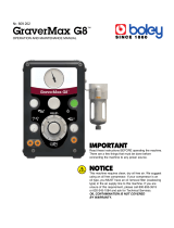
Parts Identification
General Information
SP-2A Handpiece
(standard with ST 20A-SP Systems)
TT-65 Handpiece
(standard with ST 20A-TT Systems)
PS-50 PrepSet
(standard with ST 20A-PS Systems)

6
The following are safety precautions which personnel must understand and follow
when using or servicing this product.
1. To prevent personnel injury, adhere to safety guidelines in accordance
with OSHA and other applicable safety standards.
2. SensaTemp handpiece heaters and installed tips are hot when the
handpiece is powered on. DO NOT touch either the heater or the tip.
Severe burns may result.
3. The enclosed Tip & Tool Stand has been designed specifically for use
with the your handpiece and houses it in a manner which protects the
user from accidental burns. Always store the handpiece in its Tip & Tool
Stand.
4. Always use this system in a well ventilated area. A fume extraction
system such as those available from PACE are highly recommended to
help protect personnel from solder flux fumes.
5. Exercise proper precautions when using soldering materials (e.g.,
fluxes). Refer to the Material Safety Data Sheet (MSDS) supplied with
each material and adhere to all safety precautions recommended by the
manufacturer.
6. The following safety precautions cover use of the PS 50 Prep-Set system.
a) The PS-50 Prep-Set heater and installed Pot-Tip (+ solder) or Preheat
Plate are hot when the Prep-Set is powered on and for a period of
time after power off. DO NOT touch either the heater, Preheat Plate,
Pot-Tip or solder. Severe burns may result.
b) Insure that the rubber heat shield (covering the heater) is in place.
Never operate the system without the shield in place. Severe burns
may result.
c) Turn the Power Switch off and allow the installed solder Pot-Tip or
Preheat Plate to cool before changing. Never touch a hot Pot-Tip or
Preheat Plate with bare hands.
7. POTENTIAL SHOCK HAZARD - Repair procedures on this product
should be performed by Qualified Service Personnel only. Line voltage
parts will be exposed when the equipment is disassembled. Service
personnel must avoid contact with these parts when troubleshooting the
system.
Safety

7
Set-Up
Set up the ST 20A system using the following steps and associated drawings. If you
have purchased a system which includes the TT-65 ThermoTweez handpiece or the
PS 50 Prep-Set system, refer to their Operation & Maintenance manuals for
applicable set-up instructions for those items.
1. Store the shipping container(s) in a
convenient location. Reuse of these
containers will prevent damage if you
store or ship the system.
2. Place the Power Switch in the “OFF” or
“0” position.
3. Place 4 of the supplied Rubber Feet on
the base of the power source. Remove
the paper backing and place in corner
indentations. Refer to illustration below.
Auto Off Safety System
The Auto Off Safety System removes power
from the connected handpiece after 90
minutes of handpiece inactivity. As
received from the factory, the feature is
Disabled (“2” position). The LED on the
front panel will illuminate Yellow in color
(with handpiece connected).
Refer to the description of the Auto Off Safety
System detailed in the “Operation” portion of
this manual.
To Enable (“1” position) the Auto Off feature,
perform steps 1-3.
1. Place the power source on a work
surface with the bottom facing up as
shown in the illustration.
2. Move the switch to the “1” (Enable)
position. During normal use, the LED
will now be illuminated Green in color
(with handpiece or PS-50 connected).
3. Position the system upright on a
convenient bench.

8
Set-Up
Tip & Tool Stand
If your system has been shipped with a Tip &
Tool Stand, perform the following procedure.
1. Place 4 Rubber Feet (packed with
small accessories) on the bottom
corners of any enclosed Tip & Tool
Stand.
2. If your system has been shipped with
a TT Tip & Tool Stand (for TT-65
ThermoTweez), install the bracket
using the enclosed mounting screws.

9
Set-Up
3. The Tip & Tool Stand may be used
as “free standing” or may be
attached to either side of the power
source. Attach the stand using the
following procedure.
a) Insert the 2 enclosed Mounting
Screws (head first) into the 2
power source mounting slots
shown. Slide the screws toward
the rear of the power source.
b) Place the Tip & Tool Stand
beside the power source,
inserting ends of the 2 Mounting
Screws into the 2 Tip & Tool
Stand mounting holes shown.
c) Install a knurled Thumb Nut onto
the end of each Mounting Screw.
Tighten Thumb Nuts to secure
the stand in position.
4. Place the supplied sponge in the Tip
& Tool Stand using the following
procedure.
a) Remove the 2 small punched out
center portions of the sponge &
place into the sponge well of the
stand in the position shown.
b) Place the large sponge section
into the sponge well as shown.
c) Dampen the sponges with water.
5. Place the handpiece into its Tip &
Tool Stand.

10
Set-Up
PaceLink
The PaceLink Receptacle on the front panel of
the power source allows the operator to activate
the AUTO SNAP-VAC and Controllable
PRESSURE features of a ST 60 system power
source. If an air handpiece (SX-70, TP-65 or
TJ-70) is connection to the ST 20A, actuation of
its finger switch will activate air flow through
the AUTO SNAP-VAC and Controllable
PRESSURE ports of the ST 60 system. To link
your ST 20A system to a ST 60 system, perform
the following procedure.
1. The 2 systems should be positioned
adjacent to each other. They can be placed
side by side or may be stacked one on top
of the other. Place your ST 20A system
beside or stack with your ST 60 system.
2. Use a PaceLink cable (available from
your local PACE distributor) to connect
the systems. Place the plugs on the ends
of the cable into the PaceLink
Receptacles on both systems.
3. Ensure that a VisiFilter assembly is
connected to the ST 60 AUTO SNAP-
VAC Port.
4. Connect the Air Hose of the handpiece
currently in use to the VisiFilter assembly
or Controllable PRESSURE Port.
CAUTION
Systems connected together through the PaceLink must be used and controlled
by a single operator. Any attempt to operate by more than one individual can
create a hazard condition and will cause a deterioration in performance.
Ensure that only one air hose is connected to the AUTO SNAP-VAC or
Controllable PRESSURE port at one time. Attachment to both ports
simultaneously will cause a deterioration in performance.

11
Handpiece Connection
Connect the handpiece (or PS 50) connector plug into the Power Receptacle in the
following manner.
1. Turn the Locking Ring fully
counterclockwise with the Connector
Key end facing the power source.
2. Align the Connector Key with the
Receptacle Keyway.
3. Insert the connector into the power
receptacle.
4. Turn the Locking Ring fully clockwise
to secure in place.
Air Hose Routing
When using an Air Handpiece (e.g., SX-70
Sodr-X-Tractor) or a Tip-Evac Fume Extraction
System, any associated air hose(s) can be routed
through the 2 Air Hose Feed Thru holes located
on the bottom of the power source.
System Power Up
1. Insert the female end of the power cord into the AC Power Receptacle at
the rear panel of the power source.
2. Plug the prong end (male end) of the power cord into a 3 wire grounded
AC supply receptacle. The system is now ready for operation.
CAUTION
To insure operator safety, the AC supply receptacle must be checked for
proper grounding before initial operation.
3. Read the “Operation” section of this manual thoroughly before operating
the system. Included is a description of Sodr-Pen operation. Shipped
with ST 20A-TT and ST 20A-PS systems is an additional Operation &
Maintenance manual which details operation of the TT-65 ThermoTweez
handpiece or PS-50 Prep-Set.
Set-Up

12
Sodr-Pen Tip Selection & Use
1. HEAT TRANSFER: Maximize thermal
transfer by selecting the shortest, fattest
tip with the largest surface contact area
which appropriately fits the work. Keep
the tip clean and freshly tinned and clean
the work of oxides or other residues.
When soldering, angle the tip to the joint
so that there is maximum surface contact
area. The use of a “solder bridge” to
enhance “thermal linkage” will also
improve heat transfer.
Operation
2. TIP ACCESS & VISIBILITY: The tip selected must easily contact the
joint without touching the board substrate, adjacent components or other
solder joints.
Longer, thinner, more tapered tips allow the operator to more easily
access and view the solder joint during soldering for better process
control. However, such tips generally have much less heat transfer
ability than shorter, fatter tips.

13
3. TIP TEMPERATURE: Use the lowest tip temperature which will
achieve rapid yet controllable melt of the entire joint(s). Begin with a
temperature of 316°C (600°F) and adjust as necessary to suit the
particular application and operator skill level. Lower tip temperatures
reduce the risk of damage and increase tip life.
4. SMT REMOVAL: Tips for SMT removal
applications must fit over (or around) the
component body, and contact all the solder
joints at once. When all the solder joints
reflow completely, remove the component.
5. SODR-PEN HANDPIECES: The SP-2A Sodr-Pen (comes standard
with your ST 20A-SP system) uses 3/16" shank tips providing maximum
heat transfer for Surface Mount and multilayer board applications.
The optional SP-1A Sodr-Pen uses 1/8" shank tips and features a slimmer,
more compact heater for easier access on densely populated assemblies.
Operation

14
Operation
Available Tips
Shown below is a partial listing of available single point tips plus illustrations of
different tip configurations. Contact your local authorized PACE distributor for the
Tip & Applications catalog which contains a complete list of tips.
Table I. Single Point Tips
FlatPack TipSocket Tip
SOIC Tip
3/16" Shank Thermo-Drive Tip
1/8" Shank Conical Tip
3/16" SHANK TIPS
(for SP-2A Sodr-Pen)
3/16" SHANK EXTENDED REACH
TIPS
(for SP-2A Sodr-Pen)
DESCRIPTION PART # DESCRIPTION PART #
1/64" Conical 1121-0357 1/64" Conical 1121-0528
1/64" Bent Conical 1121-0363 1/32" Conical 1121-0527
1/32" Chisel 1121-0359 1/16" Chisel 1121-0533
1/32" Bent Chisel 1121-0361 3/32" Chisel 1121-0529
1/32" Conical 1121-0336 1/8" Chisel 1121-0530
1/16" Chisel (MicroFine) 1121-0349 3/16" Chisel 1121-0531
1/16" Chisel 1121-0335 Single Sided Chisel 1121-0532
1/16" Chisel (High Capacity) 1121-0414 3/16" SHANK THERMO-DRIVE TIPS
(for SP-2A Sodr-Pen)
1/16" Chisel (Extended Reach) 1121-0499
1/16" Bent Chisel (Ext. Reach) 1121-0500 1/64" Conical 1121-0516
3/32" Chisel 1121-0360 1/64" Bent Conical 1121-0526
1/8" Chisel 1121-0337 3/64" Chisel 1121-0524
3/16" Chisel 1121-0358 3/64" Bent Chisel 1121-0525
Single Sided Chisel 1121-0406 1/16" Chisel 1121-0510
1/4" Flat Blade 1121-0402 1/8" Chisel 1121-0518
0.40" Flat Blade 1121-0305 1/8" SHANK TIPS*
(for SP-1A Sodr-Pen)
Mini-Wave 1121-0490
*These tips (1/8" shank) can be installed
in the SP-2A Sodr-Pen using the PACE
AdapTip (Part Number 1360-0083-P1).
1/32" Conical 1121-0503
1/16" Chisel 1121-0502
1/8" Chisel 1121-0501

15
Operation
NOTE
Periodically, clean the heater bore with a properly sized wire brush (3/16"
O.D. for SP-2A and 1/8" O.D. for SP-1A) to insure optimum heat transfer and
proper tip grounding.
Sodr-Pen Tip Installation
For maximum productivity and proper fit, install tips into your Sodr-Pen when the
heater is hot.
CAUTION
Hold the handpiece with the heater pointed at an angle up to prevent injury
to personnel.
1. Select the proper tip for your application. Refer to Table I or the PACE
Tip & Applications Catalog.
2. Install the selected tip in the following manner.
a) Hold the handpiece with the heater up at an angle (heater hot).
b) Insert the Tip all the way into the heater bore using the supplied Tip
Tool.
c) Gently tighten the heater Set Screw.
3. Recheck the tip Set Screw periodically to insure that it remains snug.

16
Operation
Temperature Selection
Variable Temperature Control
Adjust the Variable Temperature Control Knob
to the desired temperature setting. Notice that
the control dial has a White graphic scale
denoting temperature in °C (Celsius) and a
Yellow graphic scale denoting temperature in
°F (Fahrenheit). These numerical scales
denote the set tip temperature times 100 (e.g.,
“3” on the White scale is 3 x 100 or 300°C).
Temperature/Dial Lock
The Variable Temperature Control Knob can
be locked in position (at one temperature) to
avoid accidental or unauthorized changes of
the temperature setting. Perform the following
procedure to lock the Variable Temperature
Control Knob.
1. Adjust the Temp. Control Knob to the
desired temperature setting.
2. Using the Temp. Locking Key (hex
head wrench) included with the system,
tighten the 2 set screws on the Temp.
Locking Ring.
NOTE - Temperature will remain at its locked setting, even if the Variable
Temperature Control Knob is forced to move.
Tip Offset
Differences between the temperature settings and true tip temperatures are negligible
when using Thru-Hole, single point soldering tips. With any heating system
however, True Tip Temperatures can differ greatly from temperature settings when
using larger SMT soldering tips. This difference is called Tip Temperature Offset.
PACE recommends the use of the Tip & Temperature Selection System booklet
(PACE P/N 5050-0251) as a guide to accurately set and maintain a true tip
temperature for any size and type of SMT tip.

17
Operation
LED Operation
The tri-colored (Red, Green and Yellow) LED on the power source front panel
indicates System Status (by color illumination) and Power Receptacle output status
(LED OFF, ON or Flashing). Following is an explanation of these status indicators.
Refer to the illustration at the bottom of this page.
Green Illumination - Auto Off Safety System feature “Enabled”.
Yellow Illumination - Auto Off Safety System feature “Disabled”.
Red Illumination - Auto Off Safety System feature has turned system power off or
the connected handpiece is faulty (see Corrective Maintenance section). Turn the
system Power Switch off (“0”) and then back On (“1”) to reset the system.
LED Full On - Continuous power is being delivered to the handpiece. This
condition is evident when the system is first powered up (handpiece heater cold) or
the Variable Temperature Control setting is increased.
LED Flashing - Indicates that the set tip temperature (as set on the Variable
Temperature Control) has been reached. Power to the handpiece is cycling Off and
On to maintain set temperature.
LED Off - No power is being delivered to the handpiece heater. This condition is
evident if the Variable Temperature Control setting is decreased. If the LED never
illuminates, check for a faulty handpiece (see Corrective Maintenance section).
Auto Off Safety System
The Auto Off Safety System is a feature which,
when Enabled, (see Set-Up section of this
manual) removes power from the connected
handpiece after 90 minutes of handpiece
inactivity.
During normal use with this feature enabled,
the LED on the power source will be
illuminated Green in color (may be flashing).
When the system goes into Auto Off Mode, the
LED will illuminate Red in color.
To resume normal operation, the Power
Switch (on rear panel) must be turned Off
(“0”) position and then back On (“1”).

18
Calibration
The ST 20A system can be checked for calibration according to PACE requirements.
Also, a temperature setting normally used by the operator can be adjusted to the
precise temperature indicated on the Dial/Display. No internal adjustments can be
made to the power supply. To verify calibration of the power supply, perform the
following procedure.
1. Install a tip with an attached thermocouple wire into the handpiece
connected to the system. Tips with K type thermocouples are available
from PACE; use part number 7021-0004-P1 when ordering.
2. Connect the thermocouple assembly to a PACE Process Monitor (part
number 8001-0077 or 8001-0078) or appropriate temperature meter.
3. When set fully counterclockwise,the pointer
of the Variable Temperature Control knob
will align to the Calibration Mark as shown.
With the system turned on, adjust the
Variable Temperature Control to obtain a
stable tip temperature of 300°C (for PACE
factory specifications) or the temperature
setting normally used by the operator.
If the temperature displayed on the Process Monitor (or temperature meter)
is within ±5°C (10°F), perform steps 4 thru 6 to obtain a precise reading. If
the temperature is off by more than ±5°C, the handpiece may require
maintenance. Recheck the temperature using a second handpiece.
4. Carefully lock the Variable Temperature
Control in position by tightening the 2 inner
set screws (on Temp. Locking Ring).
5. Loosen the set screw on the Variable
Temperature Control knob. Position the
knob with the pointer aligned to match the
temperature indicated on the Process
Monitor (or temperature meter). Secure the
knob in position by tightening the set screw.
6. Loosen the 2 inner set screws (on Temp.
Locking Ring) to unlock the Variable
Temperature control if adjustment of
operating tip temperature is desired.
/