
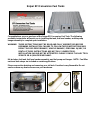
Sniper EFI Conversion Fuel Tanks
Congratulations on your purchase of the Sniper EFI Conversion Fuel Tank. The following
assembly instructions will assist you in installing the tank, fuel level sender, and the pump
hanger assembly to complete your installation.
WARNING! THESE INSTRUCTIONS MUST BE READ AND FULLY UNDERSTOOD BEFORE
BEGINNING INSTALLATION. FAILURE TO FOLLOW THESE INSTRUCTIONS MAY
RESULT IN POOR PERFORMANCE, VEHICLE DAMAGE, PERSONAL INJURY, OR
DEATH. IF THESE INSTRUCTIONS ARE NOT FULLY UNDERSTOOD,
INSTALLATION SHOULD NOT BE ATTEMPTED. PLEASE CONSULT HOLLEY TECH
SERVICE OR A QUALIFIED MECHANIC.
Kit Includes: fuel tank, fuel level sender assembly, and fuel pump and hanger. NOTE: Fuel filler
neck and tank straps are included on certain applications.
Please use caution draining and removing your old tank. Gasoline is very flammable. Do not
smoke or have any heat sources near your work area.

Fuel Sender Installation:
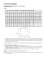
A = Tank Depth , B = Float Pivot Depth , C = Float Arm Length
(Dimensions in Inches)
TABLE 1
A = Tank Depth , B = Float Pivot Depth , C = Float Arm Length (Dimensions in Inches)
A B C A B C A B C
6.00 3.00 3.50 12.00 6.00 7.80 18.00 9.00 12.00
6.50 3.25 3.80 12.50 6.25 8.10 18.50 9.25 12.30
7.00 3.50 4.20 13.00 6.50 8.50 19.00 9.50 12.60
7.50 3.75 4.50 13.50 6.75 8.90 19.50 9.75 12.90
8.00 4.00 4.90 14.00 7.00 9.30 20.00 10.00 13.40
8.50 4.25 5.30 14.50 7.25 9.60 20.50 10.25 13.80
9.00 4.50 5.60 15.00 7.50 10.00 21.00 10.50 14.20
9.50 4.75 6.00 15.50 7.75 10.40
10.00 5.00 6.40 16.00 8.00 10.70
10.50 5.25 6.70 16.50 8.25 11.00
11.00 5.50 7.10 17.00 8.50 11.40
11.50 5.75 7.40 17.50 8.75 11.80
I. Measure depth of the fuel tank. Locate this dimension in Column “A’’ of Table 1. Column “B” shows the length from the
underside of the sender flange to the center of the float pivot. Column “C’’ shows distance from the center of the float
pivot to the center of the float. For example, a tank 12’’ deep would need a measurement of 6’’ from the flange to the
pivot and 7.8’’ from the pivot to the float.
II. For tank depths 6” to 15-1/2’’, it will be necessary to eliminate a part of the assembly. (See Fig.1) proceed as follows:
1. Remove two screws “d’’ and discard.
2. Remove two screws “e” from the plastic housing and reserve for later us.
3. Carefully remove bracket “f ’’ from the plastic housing and discard. Replace with bracket “g’’ in the housing and loosely
re-install the two screws “e’’ into housing. (6” tanks require mounting rheostat with float toward the outside of the mounting
bracket and use of only lower ”e” screw to fit)
4. Slide housing up or down until the proper dimension from Table 1 is reached, then tighten screws securely.
CAUTION: Do not overtighten hardware to avoid damage to the threads.
NOTE: For a better seal, use Permatex Indian Head Gasket Shellac Compound or Aviation Form-A-Gasket sealant on the
gasket and screws.

III. For tank depths of 16’’ to 21’’ no disassembly of the sender bracket is necessary.
1. Loosen two screws “d’’ and adjust the plastic housing up or down until the proper dimension from Table 1 is
obtained, then retighten screws securely.
IV. To install the float assembly, loosen screw “h’’, remove the short piece of rod, and discard. Insert the float rod until the
proper length “c’’ from Table 1 is met, and then tighten the screw securely. Carefully cut off any excess rod with bolt
cutter or similar tool, taking care not to damage the assembly.
NOTE: Make sure the float is installed toward the side marked “FLOAT SIDE”. If installed backwards, the fuel gauge
will indicate “full’’ when the tank is empty, and “empty’’ when the tank is full.
2. Cut the bracket (g or f) so it doesn’t extend lower than the black rheostat assembly. The rheostat should be the
lowest point of the fuel sender.
3. With the gasket in place below the flange, carefully feed the float arm and sender body into the 1.697’’ (43mm)
hole in the tank. Make certain the float arm has free motion within the tank. Using the sender flange as a
template, locate the position of the five mounting holes. Use the supplied screws to mount into the tank with
threaded inserts in place.
4. Insert fuel sender assembly into tank, align holes and thread in mounting screws. Check that all screws are
secure to complete assembly. If the float is obstructed inside the tank loosen the large nut on the center terminal
and rotate the rheostat assembly.
5. Connect the center terminal of the sender to your fuel gauge’s signal terminal. Connect the off-center terminal to
a good chassis ground.

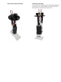
GPA- Series Pump Instructions
Plan the orientation of your supply and return fittings prior to assembly so they will be facing in the desired direction for your
installation. Keep in mind that the filter sock has to be aligned with the reservoir tray.
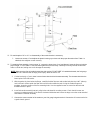
1. Measure the depth of your tank (D) by inserting a ruler down the 2-1/8” diameter accessory opening on your tank.
Determine the length of your supply and return tubes:
D = Depth of Tank S = D – P D – 1” = Return Line
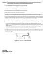
2. Trim the Return (R) and Supply (S) tubes to the lengths determined in step #1. (For GPA-5, GPA-6, GPA-8 & GPA-9
pumps D - 1-5/8”= Return Line. See reverse side for photo instruction.)
3. Slip two hose clamps over the Supply Line (do not tighten)… warm the end of the Supply Line with a heat gun... push
the pump outlet-nozzle into the Supply, being sure to use a straight motion so you don’t stress the outlet nozzle. (For
GPA-2, GPA-4 & GPA-TBI do not remove the white nylon sleeve on the pump outlet).
4. Rotate the pump until it nestles against the return line. Tighten the hose clamps and cable tie the pump to the Return
Line with two cable ties (See reverse side for photo).
5. Connect your in-tank wire harness to the fuel pump, making sure that the connections are secure. Route the wires
through the pass through fitting being sure to leave a little slack to prevent strain or chaffing, Use a 9mm wrench to
tighten the upper jam nut on the wire pass through in ¼ turn increments until the wire no linger moves up and down.
BE CAREFULL NOT TO OVERTIGHTEN DOING SO COULD BREAK THE FITTING OR CAUSE A LEAK.
6. You should consider installing an access door in the floor above your pump module.
7. For a better seal, use Permatex® P/N 85420 gasket dressing and flange sealant on the gasket and screws. When
installing using TANKS INC hardware, the torque spec is ½ ft./lb.
8. NEVER RUN YOUR PUMP DRY!
9. Pump connections are ¼” NPT. Be sure to use fuel proof thread sealer or tape.
10. For extra venting necessary for fuel injection, we have supplied a 5/16” barbed vent fitting. This can be connected to a
carbon canister or Tanks P/N VVR.

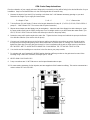
GPA-2 & GPA-4 Pump Assembly GPA-6 Pump Assembly
The return line on the GPA-6 pump must terminate before the
pump flares out to a larger diameter to fit inside of the tank
pump opening. Cut return line as shown here.

WARNING! Think safety at all times. Improper installation of a gas tank can cause the product to malfunction
and cause injury or
death to the occupants and/or damage to the vehicle.
Trial fit your tank before painting or polishing. Do not grind the welds.
Your tank must be grounded to the frame.
An in-line fuel filter is recommended.
Never fill your tank 100% full. Leave room for the cool fuel to expand.
Always remove your cap slowly. Fuel spray can cause injury.
Pipe tape is recommenced for all threaded accessory fittings, such as pickup tubes and rollover valves. A small dab of
Never-Seez®, or similar anti-galling compounds should be used to act as a lubricant and to protect the threads.
Most of our tanks are designed to work with your stock-style vented cap. We have provided an additional vent opening
in many of our tanks to help with today’s reformulated fuels. If you have changed to a non-vented cap, your installation
may require additional venting through the neck or the sending unit to prevent pressurizing the tank.
VENTING – Your tank has to breathe in both directions in order to prevent pressure or vacuum. If you are
using a non-vented cap, you must have a vent on your tank or filler neck. Run your vent hose as high as
possible in your frame. The vent should be as high as the highest point on the tank including the filler neck.
If your tank came supplied with a remote-mount aluminum rollover valve it must be mounted in a vertical
position. It should be mounted as high as or higher than your filler neck. This can be done in the frame or the
wheel-well area.
If your tank came supplied with an aluminum remote-mount rollover valve, it must be mounted in a vertical
position. It should be mounted as high, or higher than your filler tube... the higher, the better.
If you have an EFI tank with a vent in the recessed area, use the supplied “Y” fitting to plumb together the vent from the
tank with the vent from the fuel pump assembly. When installing the “Y” fitting, ensure that the fitting is as high as the
top of the tank or higher.
Technical Support: 1-866-464-6553
199R11142
Revision Date: 5-17-19
-
 1
1
-
 2
2
-
 3
3
-
 4
4
-
 5
5
-
 6
6


Ask a question and I''ll find the answer in the document
Finding information in a document is now easier with AI
Other documents
-
 SSP NPT BSPT Pipe Fittings Installation guide
-
Holley Sniper EFI 550-552 User guide
-
Holley Sniper EFI 550-510K User guide
-
 Locke TR-30 User manual
-
Holley 12-170 Operating instructions
-
BluePrint Engines Holley Sniper EFI Operating instructions
-
Toro Multi Pro 5800-G Turf Sprayer User manual
-
-
-

