Page is loading ...

2569 Kenworth Road, Suite C
Nanaimo, BC, V9T 3M4
CANADA
+1.250.729.8080
info@eddyfitechnologies.com
www.eddyfitechnologies.com
INUKTUN MAGGHD™

MaggHD™
Document: UMAU015088.docm
Revision: A08
Created by: KJB
Date: 26 Sep 2019
3080885-A08
Source Location: C:\ePDM\ISLEng\products\au-micromag\manuals\UMAU015088.docm
Page 2 of 29
User Manual
Table of Contents
About This Manual ........................................................................................................................................ 5
Description ................................................................................................................................................. 5
Specifications ............................................................................................................................................ 5
Precautions ............................................................................................................................................... 6
Certification and Directives ....................................................................................................................... 6
Safety ........................................................................................................................................................ 6
Intended Use............................................................................................................................................. 9
Laser Lines ............................................................................................................................................. 10
MaggHD™ Vehicle ................................................................................................................................. 11
Dimensions .......................................................................................................................................... 11
System Power ......................................................................................................................................... 12
Power Requirements ........................................................................................................................... 12
Generators / Inverters .......................................................................................................................... 12
Galvanic Corrosion Control ..................................................................................................................... 12
System Setup .............................................................................................................................................. 12
Personnel Requirements ........................................................................................................................ 12
Vehicle and Tether Connection .............................................................................................................. 13
Mini-Reel Setup ...................................................................................................................................... 13
Controller Connection ............................................................................................................................. 14
Configuration ............................................................................................................................................... 15
Camera Mounting ................................................................................................................................... 15
Standard Mounting ............................................................................................................................... 15
Pole Mounting ...................................................................................................................................... 16
Alternate Mounting ............................................................................................................................... 17
Operating MaggHD™ on Vertical or Inverted Surface ........................................................................... 17
Magnet Spacing ................................................................................................................................... 18
Fall Arrest ............................................................................................................................................. 19

MaggHD™
Document: UMAU015088.docm
Revision: A08
Created by: KJB
Date: 26 Sep 2019
3080885-A08
Source Location: C:\ePDM\ISLEng\products\au-micromag\manuals\UMAU015088.docm
Page 3 of 29
User Manual
Configuration Add-Ons .................................................................................. Error! Bookmark not defined.
MaggHD™ + Actuator for UT sensor ........................................................ Error! Bookmark not defined.
Probe Assembly ..................................................................................... Error! Bookmark not defined.
UT Probe Connection ............................................................................ Error! Bookmark not defined.
Couplant Pump Box Connection ............................................................ Error! Bookmark not defined.
Using the UT Probe .................................................................................. Error! Bookmark not defined.
Operation..................................................................................................................................................... 20
Tether Handling ...................................................................................................................................... 20
Connector Handling ................................................................................................................................ 20
SubConn Connector: Lubrication and Cleaning .................................................................................. 21
Impulse Connector: Lubrication and Cleaning ..................................................................................... 21
Pre-Operations Check ............................................................................................................................ 21
Post-Operations Check ........................................................................................................................... 22
ICON™ & ICON RPT™ .......................................................................................................................... 23
Driving the Vehicle .................................................................................................................................. 23
Maintenance ................................................................................................................................................ 24
Fuse Replacement .................................................................................................................................. 24
Microtrac™ Maintenance ........................................................................................................................ 24
Tether Re-termination ............................................................................................................................. 24
Troubleshooting .......................................................................................................................................... 25
Camera Control Problems ...................................................................................................................... 25
Video Issues ........................................................................................................................................... 25
Vehicle Issues ......................................................................................................................................... 25
Tether Reel Issues .................................................................................................................................. 26
Parts and Repairs ....................................................................................................................................... 27
Ordering Parts/Customer Service ........................................................................................................... 27
Warranty Repairs .................................................................................................................................... 27
Factory Returns to Canada ..................................................................................................................... 28

MaggHD™
Document: UMAU015088.docm
Revision: A08
Created by: KJB
Date: 26 Sep 2019
3080885-A08
Source Location: C:\ePDM\ISLEng\products\au-micromag\manuals\UMAU015088.docm
Page 4 of 29
User Manual
Product/System Drawing Package Availability ....................................................................................... 28
Limited Warranty Policy .............................................................................................................................. 28

MaggHD™
Document: UMAU015088.docm
Revision: A08
Created by: KJB
Date: 26 Sep 2019
3080885-A08
Source Location: C:\ePDM\ISLEng\products\au-micromag\manuals\UMAU015088.docm
Page 5 of 29
User Manual
About This Manual
This manual has been prepared to assist you in the operation and maintenance of your Eddyfi
Technologies Inuktun equipment. Correct and prudent operation rests with the operator who must
thoroughly understand the operation, maintenance, service and job requirements. The specifications and
information in this manual are current at the time of printing.
This product is continually being updated and improved. Therefore, this manual is meant to explain and
define the functionality of the product. Furthermore, schematics or pictorials and detailed functionality
may differ slightly from what is described in this manual.
Eddyfi Technologies reserves the right to change and/or amend these specifications at any time without
notice.
Information in this manual does not necessarily replace specific regulations, codes, standards, or
requirements of others such as government regulations.
This manual copyright © 2019 by Inuktun Services Ltd. All rights reserved.
Description
The Inuktun MaggHD™ is a magnetic tracked crawler capable of driving vertically or inverted along
ferrous surfaces. Additionally, the magnet modules allow the vehicle to pull longer lengths of tether than
could normally be achieved without magnets, when travelling horizontally in steel pipes or on steel decks.
The crawler features a high definition camera with a full 360-degree continuous tilt range and minimal
viewing obstruction near the back of the vehicle. The vehicle uses two extended 4000 series Microtracs™
mounted underneath the main chassis plate and can be moved up or down to accommodate different
pipe sizes and configurations.
Specifications
Specifications
Details
Depth Rating
60 m (200 ft)
Weight
6.2 kg (14 Ib)
Front Facing Camera
Full HD, 10x Optical Zoom, 12x Digital, Continuous Tilt
Tracks
4000 Series Microtracs™
Light (Variable)
2x In-Camera LEDs
2x Optional External 801 Lights
Lasers
2x Optional Vertical Laser Lines, 635 nm, 70 mm (2.75 in) Spacing
Supported Software
ICON™ & ICON RPT™
Power Requirements
110-240VAC, 50/60Hz, 550W Minimum
Operating Temperature
0 ° – 50 °C (32 ° – 122 °F) *Dependent on operating conditions. Ask
your sales expert for more information.
Storage Temperature
-20 ° – 60 °C (0 ° – 140 °F)

MaggHD™
Document: UMAU015088.docm
Revision: A08
Created by: KJB
Date: 26 Sep 2019
3080885-A08
Source Location: C:\ePDM\ISLEng\products\au-micromag\manuals\UMAU015088.docm
Page 6 of 29
User Manual
Precautions
IMPORTANT: When configuring a 70V system, check to see if the tracks are
compatible. Older versions of 4000 series Microtracs™ are not 70V
compatible. Look for the Wide Input Voltage symbol \V/ located on the side
plate of the track indicating 70V compatibility.
Certification and Directives
This system is built in accordance with the Low Voltage Directive 2006/95/EC and Directive 2014/35/EU,
Machinery Directive 2006/42/EC, and Electromagnetic Compatibility Directive 2004/108/EC and Directive
2014/30/EU.
Safety
To use this product properly and safely, every user must first read these operating instructions and
observe the safety instructions contained therein. Take care of these operating instructions and keep
them in a place where they can be accessed by everyone. Untrained personnel should not handle or
operate this equipment.
CAUTION: Failure to follow these safety instructions may result in injury or
equipment damage.
WARNING: Hazardous Voltage 36-70 VDC. If the equipment is powered from a
source other than an Eddyfi Inuktun provided controller, the power supplied to the
product must have reinforced isolation from the mains with no reference to earth
ground.
WARNING: Magnetic Pinch Hazard – The magnetic
chassis is fitted with rare earth magnets. These magnets
are very strong and create an immanent pinch hazard.
Use caution when handling the magnets or vehicle near
steel objects and tools, they may snap together
unexpectedly.
Note: Rare earth materials are mechanically weak, and
magnetically very strong. They must therefore be
handled very carefully to avoid damage.

MaggHD™
Document: UMAU015088.docm
Revision: A08
Created by: KJB
Date: 26 Sep 2019
3080885-A08
Source Location: C:\ePDM\ISLEng\products\au-micromag\manuals\UMAU015088.docm
Page 7 of 29
User Manual
WARNING: Medical Hazard – Operators with magnetically sensitive medical implants should
be aware of and follow appropriate practices.
WARNING: Electronic Device Interference – Magnetically sensitive devices, including
computer hard drives, cell phones, watches and credit cards may be disrupted or damaged by
the magnetic field.
Note: To reduce risk of injury and damage to equipment, always store the
MaggHD™ vehicle in its magnetically shielded storage and shipping box
when not in use.
Note: Eddyfi strongly recommends using gloves when handling the vehicle to
reduce magnetic pinching hazard.
Warning: Avoid Magnetic Slamming. Extreme care must be taken when
handling the vehicle, particularly when placing it onto a wall or into its storage
box. Without taking heed of the sudden pull of the magnetic field onto surface,
the MaggHD™ can be slammed down hard causing damage to the vehicle.
Using a solid grip on the vehicle, we recommend touching down the vehicle by
one end first and then pivoting flat.
WARNING: Intense Optical Radiation - The MaggHD™ camera lights are
extremely bright. Never look directly at the lights. Use a welding filter (shade #8 or
higher) if inspecting the LEDs.

MaggHD™
Document: UMAU015088.docm
Revision: A08
Created by: KJB
Date: 26 Sep 2019
3080885-A08
Source Location: C:\ePDM\ISLEng\products\au-micromag\manuals\UMAU015088.docm
Page 8 of 29
User Manual
• CAUTION: Class II Laser: Do not intentionally stare into the
beam. Typically, Class II relies on the blink reflex to limit
exposure to no more than ¼-second. Intentionally staring into
the beam can cause eye injury.
• When performing maintenance or functional checks of the
lasers and camera lights, take precautions to protect nearby
personnel from unintended exposure which could be
temporarily blinding.
• Observe safe lifting practices. For storage and shipping, the MaggHD™ system is packed in three
parts: Controller, Vehicle and Tether. Each of the three components is either built or packed into
a Pelican case with carrying handle. The heaviest case containing the tether and mini-reel is
equipped with wheels and extending handle like a suitcase.
• Do not operate the system with damaged wires. A short circuit may damage the power system,
telemetry system, cameras, or attached equipment. Exposed wires may also create a shock
hazard.
• Disconnect the power source before servicing the product; otherwise, damage may result.
• Although designed for durability, the vehicle and its components or attached devices may suffer
structural damage if dropped or impacted. A lifeline or fall arrest system should be used at all time
when the vehicle is navigating on a vertical or inverted horizontal position. In addition, stepping on
the tether may pull the vehicle off the wall causing it to fall and sustain physical damage.
• All personnel operating or maintaining this equipment must be trained and competent.
• Our equipment is used in many varied environments from hot/dry to confined spaces to deep
underwater. Such diverse environment risks must be addressed by the operators who are trained
to work in such surroundings. As such, the operator is responsible to determine safe site setup
and appropriate personal protective equipment (PPE) for operation and maintenance of the
equipment.
WARNING: Spark Hazard - Under no circumstances should this equipment be
used in a potentially explosive atmosphere.
WARNING: Trip Hazard - Never stand on the tether. A snap load to the tether
may pull it out from underneath you and cause you to fall. Standing on the tether
may also damage its internal conductors, cause unnecessary wear, and decrease
its life.
WARNING: High Temperature - The camera head and auxiliary lights may
become extremely hot during operation. Allow a cool-down period before
handling.

MaggHD™
Document: UMAU015088.docm
Revision: A08
Created by: KJB
Date: 26 Sep 2019
3080885-A08
Source Location: C:\ePDM\ISLEng\products\au-micromag\manuals\UMAU015088.docm
Page 9 of 29
User Manual
WARNING: Falling Object - A lifeline or fall arrest system should be used at all
times when the vehicle is navigating on a vertical or inverted horizontal position.
When the vehicle is climbing, never stand below the vehicle operations area.
Intended Use
The MaggHD™ is an industrial inspection vehicle intended for crawling on steel walls, tanks and
structures and to provide close-up or zoom HD video of the inspection target, which could be a weld,
paint covering, etc. The MaggHD™ may be used above or below the waterline up to 60 m (200 ft) deep,
or in dry environments. It may also be used in non-magnetic environments with removal of the magnet
cups.
Typical applications include:
• Underwater weld and paint inspection
• Potable water system inspection
• Steel Tank inspection
• Large diameter pipe inspection
• Mobile robotics and remote sensing
• Reactor vessel inspection
Misuse of the system is deployment in a situation for which it is not rated, or incorrect handling.
Examples of misuse include:
• In a vacuum
• Beyond its depth rating without factory approval
• Above or below its temperature rating
• Use in a potentially explosive atmosphere
• Use in incompatible chemical environments
• Very high radiation environments (Beta / Gamma)
• Prolonged overload (Payload or pulling load)
• Camera pointed at the Sun or at intense lighting
• Mechanical impacts & scraping during deployment / magnetic slamming / dropping
• In salt water without an anode

MaggHD™
Document: UMAU015088.docm
Revision: A08
Created by: KJB
Date: 26 Sep 2019
3080885-A08
Source Location: C:\ePDM\ISLEng\products\au-micromag\manuals\UMAU015088.docm
Page 10 of 29
User Manual
Laser Lines
The MaggHD™ may be optionally equipped with vertical laser lines (Class 2 lasers at 635 nm, 1.5 mW).
Laser line separation is 70 mm (2.75 in).
CAUTION: Class II Laser: Do not intentionally stare into the
beam. Typically, Class II relies on the blink reflex to limit
exposure to no more than ¼-second. Intentionally staring into
the beam can cause eye injury.
When performing maintenance or functional checks of the
lasers and camera lights, take precautions to protect nearby
personnel from unintended exposure which could be
temporarily blinding.
FIGURE 1 – LASER LINE SEPARATION

MaggHD™
Document: UMAU015088.docm
Revision: A08
Created by: KJB
Date: 26 Sep 2019
3080885-A08
Source Location: C:\ePDM\ISLEng\products\au-micromag\manuals\UMAU015088.docm
Page 11 of 29
User Manual
MaggHD™ Vehicle
FIGURE 2: VEHICLE
Dimensions
FIGURE 3: VEHICLE DIMENSIONS

MaggHD™
Document: UMAU015088.docm
Revision: A08
Created by: KJB
Date: 26 Sep 2019
3080885-A08
Source Location: C:\ePDM\ISLEng\products\au-micromag\manuals\UMAU015088.docm
Page 12 of 29
User Manual
System Power
Power Requirements
The MaggHD™ is operated through an ICON™ Portable Controller, or a Rackmount Interface Box. These
controllers provide power to the tether and vehicle.
Refer to the Controller User Manual for further details and power requirements.
Generators / Inverters
If powering the system from a generator or inverter, refer to that unit’s operating manual for
recommendations on continuous and peak load ratings. These power sources may apply a reduced
output rating based on electrical load and environmental temperature. Remember to include the power
needs of all other connected devices (external monitors, recording devices, lighting, etc.) when selecting
a generator or inverter.
Galvanic Corrosion Control
We strongly recommend cathodic protection whenever the vehicle is being deployed in a salt water
environment, either submerged or in salt spray. We recommend aluminum marine anodes exclusively for
use with the inspection system. Aluminum anodes are common in the marine industry and are replacing
zinc anodes in many areas. For inspection systems that are often pulled in and out of salt water,
aluminum anodes are especially important, as zinc anodes tend to scale over when exposed to air and
may not reactivate when submerged again. An aluminum anode will always reactivate.
For permanent installations, it is required that the structure to which the system is mounted also be
protected by aluminum anodes. If the structure is of a dissimilar metal, the system mount must be
isolated from the structure. Do not mix anode types (zinc and aluminum) on the assembly. There must be
only one anode type throughout the structure. Avoid use of Magnesium anodes altogether.
System Setup
Personnel Requirements
Basic deployment of the MaggHD™ system may be performed by one person. Operations at more
complex worksites may require two people, especially when the console location is removed from the
point of deployment.
• Console Operator: This person is responsible for driving the vehicle, watching the location of the
inspection and making comments about it and the surrounding conditions. It is also the operator’s
responsibility to assess whether the location of the inspection is in the appropriate condition for
safe passage of the vehicle or if there is a risk of getting stuck. The operator may also assist in
general site setup (cones, warning signs, etc.), vehicle maintenance and configuration.
• Deployment / Tether Handler / Field Maintenance: This person has several tasks including:

MaggHD™
Document: UMAU015088.docm
Revision: A08
Created by: KJB
Date: 26 Sep 2019
3080885-A08
Source Location: C:\ePDM\ISLEng\products\au-micromag\manuals\UMAU015088.docm
Page 13 of 29
User Manual
o Configuring the vehicle for the current inspection
o Placing and retrieving the vehicle to and from the inspection area
o Watching the tether as the vehicle enters and exits the inspection
o Operating the reel and winding the tether during recovery
Establish a good channel of communication between the operator and deployment personnel. Good
communication can avoid accidents, damage to the equipment, and promotes efficiency and productivity.
In particular, the person deploying the vehicle and watching the tether must be able to quickly tell the
operator to stop the vehicle if something goes wrong. The operator should never turn on power or initiate
movement without first communicating with the vehicle handler.
Vehicle and Tether Connection
The tether and vehicle are depth rated to 60 m (200 ft) of water. The tether connector and track
connectors are dry-mate types which must be dry when making a connection. Keep the tether connector
capped with a dummy plug when not connected to the vehicle to help keep out dirt.
It is important that the tether be properly connected to the vehicle.
1. Connect the vehicle end of the tether to the back of the harness block. Visually line up the key in
the connector before mating. Fully screw down and hand tighten the locking collar.
2. Verify the track and camera whips from the harness block to their respective components are
securely connected, and the whips are free from damage.
Mini-Reel Setup
If your system includes a Mini-Reel, follow these steps to operate:
1. Remove the Mini-Reel from the shipping case
2. Connect the deck cable from the reel to the controller
3. Connect the encoder deck cable from the reel to the Video Interface and Power Supply (if
provided with Mini-Reel)
4. Disengage the shipping brake
5. Make sure the friction brake is engaged – disengaging the friction brake can result in slack tether
resulting in potentially jamming the reel
6. Unwind some tether and connect the tether to the vehicle

MaggHD™
Document: UMAU015088.docm
Revision: A08
Created by: KJB
Date: 26 Sep 2019
3080885-A08
Source Location: C:\ePDM\ISLEng\products\au-micromag\manuals\UMAU015088.docm
Page 14 of 29
User Manual
FIGURE 4: MINI-REEL
Controller Connection
Refer to controller user manual for setup instruction and operation details.

MaggHD™
Document: UMAU015088.docm
Revision: A08
Created by: KJB
Date: 26 Sep 2019
3080885-A08
Source Location: C:\ePDM\ISLEng\products\au-micromag\manuals\UMAU015088.docm
Page 15 of 29
User Manual
Configuration
Camera Mounting
The MaggHD™ camera can be mounted in a standard configuration or can be removed from the vehicle
and mounted on an accessory pole. The camera can also be mounted in an alternate orientation option.
Standard Mounting
To install the camera onto the vehicle, do the following (removal is the reverse of installation):
1. Make sure the starboard axle screw is fully disengaged (tip should be slightly recessed in round
housing).
2. Slide the camera between the chassis fairings, make sure the connector is oriented as shown
and the washer is located with the locking nut on the outside of the fairing (see below).
3. Making sure the connector stem is seated all the way down in the port fairing slot, tighten the axle
screw; make sure it cleanly enters the bronze bushing in the camera head.
4. Tighten the port side locking nut.
5. Connect the camera whip to the bulkhead connector.
FIGURE 5: STANDARD MOUNTING

MaggHD™
Document: UMAU015088.docm
Revision: A08
Created by: KJB
Date: 26 Sep 2019
3080885-A08
Source Location: C:\ePDM\ISLEng\products\au-micromag\manuals\UMAU015088.docm
Page 16 of 29
User Manual
Pole Mounting
Mounting the camera onto the optional inspection pole is nearly identical to the standard installation (see
below).
FIGURE 6: POLE MOUNTING

MaggHD™
Document: UMAU015088.docm
Revision: A08
Created by: KJB
Date: 26 Sep 2019
3080885-A08
Source Location: C:\ePDM\ISLEng\products\au-micromag\manuals\UMAU015088.docm
Page 17 of 29
User Manual
Alternate Mounting
Mounting the camera onto the optional mount is as follows (removal is the reverse of installation):
1. Remove one magnet cup M5x30 SHCS from each side of the vehicle as shown below.
2. Install the optional mount with 2x M5x30 SHCS and 4x M4x12 SHCS as shown.
3. Install the camera onto the mount, making sure to fully seat the connector stem into its mounting
slot and tighten the lock nut.
FIGURE 7: ALTERNATE MOUNTING
Operating MaggHD™ on Vertical or Inverted Surface
The MaggHD™ vehicle comes equipped with magnet cups to enable the vehicle to maneuver on a
vertical or inverted magnetically attractive surface. The magnet cups utilize rare earth permanent magnets
and cannot be disabled (or turned off).
The inspection surface must be carbon steel or alloy steel that has good magnetic properties. Most
structural steels are strongly magnetic. 300 series stainless steels and some other alloys are not. The
client may be able to identify their metal and look up its properties or test it with a magnet.
It is important to note that the magnet cups lose magnetic adhesion as they move away from the
attractive surface. The operator needs to pay attention to distance between the magnet cups and the
surface. If the magnets are too close to the surface, the Microtracs™ may not be able to overcome the
added friction for skid steering. If the magnets are too far away the vehicle may lose magnetic adhesion.
The distance from the magnet cups to the inspection surface can be adjusted by the operator by adding
or removing the magnet spacers. The thickness of the steel surface also affects the amount of magnetic
adhesion provided by the magnets.

MaggHD™
Document: UMAU015088.docm
Revision: A08
Created by: KJB
Date: 26 Sep 2019
3080885-A08
Source Location: C:\ePDM\ISLEng\products\au-micromag\manuals\UMAU015088.docm
Page 18 of 29
User Manual
Some considerations when determining magnet spacing:
• Thickness of stainless, plastic, or concrete cladding over the carbon steel surface
• Uneven surfaces such as large welds
• Thickness of magnetically attractive surface (0.20in minimum is ideal)
• Curvature of inspection surface
Magnet Spacing
The MaggHD™ vehicle comes with the tracks spaced down from the main chassis plate using four
groups of 8mm and 4.5mm spacers (two groups per track). The vehicle comes with a kit of spacers to
accommodate a wide range of track spacing.
Use the following mounting hardware depending on the track spacers used:
• When spacing the tracks between 6-12 mm (0.25-0.5 in), use M5x20 SHCS outboard and M5x25
SHCS inboard.
• For spacing less than 6 mm (0.25 in), use M5x14 SHCS outboard and M5x18 SHCS inboard.
• When spacing the tracks more than 12 mm (0.50 in), use M5x25 SHCS outboard and M5x30
SHCS inboard.
When remounting the tracks, make sure the whips are securely connected and the locking collars are
fully engaged. Be careful to not pinch the track whips, and route them upwards towards the top of the rear
crossbar.
FIGURE 8: MAGNET SPACING

MaggHD™
Document: UMAU015088.docm
Revision: A08
Created by: KJB
Date: 26 Sep 2019
3080885-A08
Source Location: C:\ePDM\ISLEng\products\au-micromag\manuals\UMAU015088.docm
Page 19 of 29
User Manual
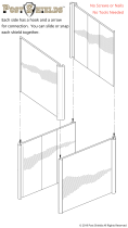
Fall Arrest
IMPORTANT: A lifeline or fall arrest system should always be used when vehicle detachment
from the working surface threatens injury to personnel or damage to equipment. A fall arrest
system can be attached to the vehicle on either or both chassis handles.
Additionally, one of the handles may be relocated using the two mounting holes located behind
the camera.
FIGURE 9 - FALL ARREST

MaggHD™
Document: UMAU015088.docm
Revision: A08
Created by: KJB
Date: 26 Sep 2019
3080885-A08
Source Location: C:\ePDM\ISLEng\products\au-micromag\manuals\UMAU015088.docm
Page 20 of 29
User Manual
Operation
Tether Handling
The tether is one of the most important parts of the system. It feeds power and control signals to the
system and returns data to the controller. If the tether is damaged from improper use, poor handling or an
accident, the system may become inoperable. This could lead to significant downtime, loss of production,
and avoidable costly repairs. It is encouraged to stress the importance of the tether and its use to anyone
operating or maintaining the system. For maximum tether life and reliability, we recommend the following
tether handling tips.
• Do not step on the tether
• Do not drive over the tether
• Do not bend the tether beyond its minimum bend radius
• Do not kink the tether
• Do not snap load the tether
• Avoid loading the tether whenever possible
• Always use the cable grip strain relief if applicable to your system
• Regularly inspect the tether for damage
• Regularly clean the tether
Note:
Protecting the conductors inside the tether is critical to the life and operation of the tether.
Proper tether handling and care will result in extended tether life and system reliability.
Connector Handling
Connectors are an essential part of system reliability. They should be properly maintained and cared for
to ensure long life and reliability. It is recommended to follow these steps to help prevent damage and
increase the life of connectors.
• Always put the cap back on the tether bulkhead when the tether is disconnected
• Always inspect the end of the connector prior to engaging
• Never plug in a dirty or damaged connector
• Visually align key-ways or locating pins prior to engaging the connector
• Always fully engage or tighten the connector
• Secure locking collars finger tight
• Install dummy plugs on unused connectors
• Disconnect by pulling straight, not on an angle
• Do not pull on the cable to disengage the connector
IMPORTANT: Never “Hot Plug” any connector, this will result in internal damage to the
electronics. Power down the system prior to connecting the inspection system tether.
/