ProCom Heating 120017 User manual
- Category
- Space heaters
- Type
- User manual
This manual is also suitable for

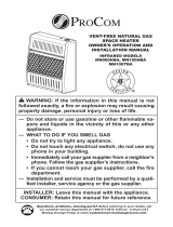
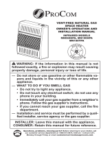
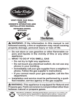
VENT-FREE GAS WALL
HEATER
OWNER’S OPERATION AND
INSTALLATION MANUAL
BLUE FLAME MODEL
MTF30TBU
Questions, problems, missing parts? Before returning to your retailer, call
our customer service department at 1-866-573-0674, 8:00 am - 4:30 pm CST,
Monday through Friday or email customerservice@usaprocom.com
PFS
®
US
FAN
HOT
Cedar Ridge
hearth
®
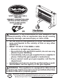
WARNING: If the information in this manual is not
followed exactly, a re or explosion may result causing
property damage, personal injury or loss of life.
— Do not store or use gasoline or other ammable va-
pors and liquids in the vicinity of this or any other
appliance.
— WHAT TO DO IF YOU SMELL GAS
• Do not try to light any appliance.
• Do not touch any electrical switch; do not use any
phone in your building.
•
Immediately call your gas supplier from a neighbor’s
phone. Follow the gas supplier’s instructions.
• If you cannot reach your gas supplier, call the re
department.
—
Installation and service must be performed by a quali-
ed installer, service agency or the gas supplier.
WARNING: This appliance is equipped for Natural and
Propane gas. Field conversion is not permitted other than
between natural or propane gases.

www.usaprocom.com
200006-01A2
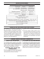
TABLE OF CONTENTS
Safety ........................................................ 3
Specications ............................................ 4
Important Electrical Safety Information...... 5
Qualied Installing Agency ........................ 6
Product Features ....................................... 6
Local Codes............................................... 6
Preparing For Installation .......................... 7
Unpacking.................................................. 7
Water Vapor: A By-Product Of
Unvented Room Heaters ..................... 7
Air For Combustion and Ventilation ........... 8
Installation ................................................11
Operation ................................................. 18
Electrical Connection ............................... 21
Electrical Wiring Diagram ........................ 22
Inspecting Burners................................... 23
Care And Maintenance ............................ 24
Troubleshooting ....................................... 25
Parts ........................................................ 28
Replacement Parts .................................. 30
Accessories ............................................. 30
Service Hints ........................................... 31
Technical Service..................................... 31
Warranty .................................................. 32
INSTALLER: Leave this manual with the appliance.
CONSUMER: Retain this manual for future reference.
This is an unvented gas-red heater. It uses air (oxygen)
from the room in which it is installed. Provisions for ad-
equate combustion and ventilation air must be provided.
Refer to Air For Combustion and Ventilation section on
page 8 of this manual.
WARNING: Improper installation, adjustment, al-
teration, service or maintenance can cause injury or
property damage. Refer to this manual for correct in-
stallation and operational procedures. For assistance
or additional information consult a qualied installer,
service agency or the gas supplier.
This appliance may be installed in an aftermarket,* per-
manently located, manufactured (mobile) home, where
not prohibited by local codes.
This appliance is only for use with propane or natural
gas. This appliance is equipped with a simple means to
switch between propane and natural gas. Field conver-
sion by any other means including the use of a kit is
not permitted.
* Aftermarket: Completion of sale, not for purpose of resale, from the manufacturer.
SAVE THIS BOOK

www.usaprocom.com
3200006-01A
SAFETY
IMPORTANT: Read this owner’s
manual carefully and completely
before trying to assemble, op-
erate, or service this heater.
Improper use of this heater can
cause serious injury or death
from burns, fire, explosion,
electrical shock and carbon
monoxide poisoning.
Only a qualied installer, service
agent, or local gas supplier may
install and service this product.
WARNING: Keep the appli-
ance area clear and free from
combustible materials, gasoline,
and other ammable vapors and
liquids.
WARNING: This appliance
can be used with propane or
natural gas. It is shipped from
the factory adjusted for use with
propane.
This appliance is only for use
with the type of gas indicated on
the rating plate. This appliance
is not convertible for use with
other gases.
CARBON MONOXIDE POISONING: Early
signs of carbon monoxide poisoning resemble
the u, with headaches, dizziness or nausea.
If you have these signs, the heater may not be
working properly. Get fresh air at once! Have
heater serviced. Some people are more af-
fected by carbon monoxide than others. These
include pregnant women, people with heart or
lung disease or anemia, those under the inu-
ence of alcohol and those at high altitudes.
NATURAL AND PROPANE/LP GAS: Natural
and Propane/LP gas are odorless. An odor-
making agent is added to the gas. The odor
helps you detect a gas leak. However, the
odor added to the gas can fade. Gas may be
present even though no odor exists.
WARNING: Any change to
this heater or its controls can
be dangerous.
WARNING: Do not use any
accessories not approved for
use with this heater.
WARNING: Carefully super-
vise young children when they
are in the room with the heater.
WARNING: Make sure grill
guard is in place before running
heater.
WARNING: Due to high tem-
peratures, the appliance should
be located out of trafc and away
from furniture and draperies.
WARNING: Heater becomes
very hot when running. Keep
children and adults away from
hot surfaces to avoid burns or
clothing ignition. Heater will re-
main hot for a time after shutoff.
Allow surfaces to cool before
touching.
WARNING: Do not place
clothing or other flammable
material on or near the appli-
ance. Never place any objects
in the heater.

www.usaprocom.com
200006-01A4
1. Do not place Propane/LP supply tank(s)
inside any structure. Propane/LP supply
tank(s) must be placed outdoors.
2. This heater shall not be installed in a
bedroom or bathroom.
3. This heater needs fresh air ventilation to
run properly. This heater has an Oxygen
Depletion Sensing (ODS) safety shutoff
system. The ODS shuts down the heater
if not enough fresh air is available. See Air
for Combustion and Ventilation, pages 8
through 9. If heater keeps shutting off, see
Troubleshooting, page 25.
4. Keep all air openings in front and bottom
of heater clear and free of debris. This will
ensure enough air for proper combustion.
5. If heater shuts off, do not relight until you
have provided fresh, outside air. If heater
keeps shutting off, have it serviced.
6. Do not run heater:
• Where ammable liquids or vapors are
used or stored.
• Under dusty conditions.
SAFETY
7. Before using furniture polish, wax, carpet
cleaner, or similar products, turn heater
off. If heated, the vapors from these prod-
ucts may create a white powder residue
within burner box or on adjacent walls or
furniture.
8. Do not use heater if any part has been
under water. Immediately call a qualied
service technician to inspect the room
heater and to replace any part of the
control system and any gas control which
has been under water.
9. Turn off and unplug heater and let cool
before servicing. Only a qualied service
person should service and repair heater.
10. Operating heater above elevations of
4,500 feet could cause pilot outage.
11. To prevent performance problems, do
not use propane/LP fuel tank of less than
100 lbs. capacity.
SPECIFICATIONS
Model MTF30TBU
Gas Type Natural Gas Propane Gas
Ignition Electric Piezo Ignitor Electric Piezo Ignitor
BTU/Hr (available)
Maximum 25,000 Maximum 24,000
Minimum 16,000 Minimum 20,000
Pressure Regulator Setting 4" W.C. 9" W.C.
Inlet Gas Pressure*
(inches of water)
Maximum 10.5" Maximum 14"
Minimum 5" Minimum 11"
Electric Power
Voltage • 120 VAC, 60 Hz
Power • 1500 Watts
Heater Dimensions (HxWxD) •
17.34" × 28" × 6.7"
Carton Dimensions (HxWxD) •
19.25" × 30" × 7.5"
Heater Weight • 28.6 lbs
Shipping Weight • 32.5 lbs

www.usaprocom.com
5200006-01A
IMPORTANT ELECTRICAL SAFETY INFORMATION
When using electrical appliances, basic pre-
cautions should always be followed to reduce
the risk of re, electric shock, and injury to
persons, including the following:
1. Read all instructions before using this
heater.
2. This appliance is hot when in use. To avoid
burns, do not come in contact with heater.
Keep combustible materials, such as fur-
niture, pillows, bedding, papers, clothes,
and curtains at least 3 feet (1 m) from the
front of the heater, and keep them away
from the sides and rear.
3. Extreme caution is necessary when any
heater is used by or near children or
invalids and whenever the heater is left
operating and unattended.
4. Do not operate any heater with a damaged
cord or plug or if the heater malfunctions,
has been dropped or damaged in any
manner. Have heater repaired by a quali-
ed service person.
5. Under no circumstances should this elec-
tric heater be modied. Parts having to be
removed for servicing must be replaced
prior to operating this electric heater
again.
6. Do not use outdoors.
7. This heater is not intended for use in
bathrooms, laundry areas or similar indoor
locations. Never use this appliance near
a bathtub or other water container.
8. Do not run cord under carpeting. Do not
cover cord with throw rugs, runners or
similar coverings. Arrange cord away from
trafc areas and where it will not be tripped
over.
9. To disconnect heater, turn controls to OFF,
then remove plug from outlet.
10. Connect to properly grounded outlets only.
11. When this appliance is installed, it must be
electrically grounded in accordance with
local codes with the current CSA C22.1
Canadian local codes for USA installa-
tions. Follow local codes and National
Electrical Code, ANSI/NFPA NO.70 and
Canadian Cord: C 22.2 NO.0.
12. Do not insert or allow foreign objects to
enter any ventilation or exhaust opening
as this may cause electric shock, re or
damage to the heater.
13. To prevent a possible re, do not block
air intakes or exhaust in any manner. Do
not use on soft surfaces, such as a bed,
where openings may become blocked.
14. This heater gets hot and contains internal
parts that sparks and arcs. Do not use it in
areas where gasoline, paint, or ammable
liquids are used or stored.
15. Use this heater only as described in this man-
ual. Other uses not recommended by the
manufacturer may cause fire, electric
shock, or injury.
16. Avoid the use of an extension cord be-
cause it may overheat and cause a risk
of re. However if you must use an exten-
sion cord, the cord shall be No. 14AWG
minimum size and rated not less than
1900 watt. The extension cord must be a
three wire cord with grounding type plug
and cord connector.
17. This electric heater should not be used
as a drying rack for clothing. Also, do not
hang Christmas stockings or decorations
on or near it.

www.usaprocom.com
200006-01A6
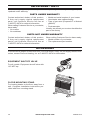
PRODUCT FEATURES
SAFETY PILOT
This heater has a pilot with an Oxygen Deple-
tion Sensing (ODS) safety shutoff system. The
ODS/pilot shuts off the heater if there is not
enough fresh air.
THERMOSTATIC CONTROL
The control automatically cycles the burner
on and off to maintain a desired room
temperature.
2 GAS OPTIONS AVAILABLE
Your heater is equipped to operate on either
Propane/LP or Natural gas. The heater is
shipped from the factory ready for connect-
ing to Propane/LP. The heater can easily be
changed to Natural gas by having your quali-
ed installer follow the instructions on page
16 and the markings on the heater.
LOCAL CODES
Install and use heater with care. Follow all
local codes. In the absence of local codes,
use the latest edition of The National Fuel
Gas Code, ANSI Z223.1/NFPA 54*.
*Available from:
American National Standards Institute, Inc.
1430 Broadway
New York, NY 10018
National Fire Protection Association, Inc.
1 Batterymarch Park
Quincy, MA 02269-9101
This heater is designed for vent-free op-
eration. State and local codes in some areas
prohibit the use of vent-free heaters.
State of Massachusetts: The installation
must be made by a licensed plumber or
gas tter in the Commonwealth of Mas-
sachusetts.
Sellers of unvented propane or natural
gas-red supplemental room heaters shall
provide to each purchaser a copy of 527
CMR 30 upon sale of the unit.
In the State of Massachusetts the gas
cock must be a T-handle type. The State
of Massachusetts requires that a exible
appliance connector cannot exceed three
feet in length.
QUALIFIED INSTALLING AGENCY
Only a qualied agency should install and
replace gas piping, gas utilization equipment
or accessories, and repair and equipment ser-
vicing. The term “qualied agency” means any
individual, rm, corporation, or company that
either in person or through a representative
is engaged in and is responsible for:
a) Installing, testing, or replacing gas piping
or
b) Connecting, installing, testing, repairing,
or servicing equipment; that is experienced
in such work; that is familiar with all precau-
tions required; and that has complied with
all the requirement of the authority having
jurisdiction.

www.usaprocom.com
7200006-01A
FAN
HOT
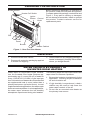
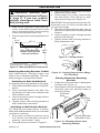
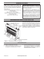
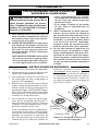
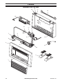
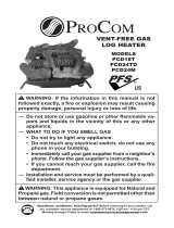
PREPARING FOR INSTALLATION
Before beginning assembly or operation of
the product, make sure all parts are present.
Compare parts with package contents list and
Figure 1. If any part is missing or damaged,
do not attempt to assemble, install or operate
the product. Contact customer service for
replacement parts.
UNPACKING
1. Remove heater from carton.
2. Remove all protective packaging applied
to heater for shipping
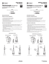
Figure 1 - Vent-Free Gas Heater
Control
Knob
Ignitor
Button
Blower Switch
Heater Coil Switch
Front
Panel
Grill
Burner
Heater Cabinet
3. Check heater for any shipping damage. If
heater is damaged, promptly inform dealer
where you bought heater.
WATER VAPOR: A BY-PRODUCT OF
UNVENTED ROOM HEATERS
Water vapor is a by-product of gas combus-
tion. An unvented room heater produces ap-
proximately one (1) ounce (30 mL) of water for
every 1,000 BTUs (0.3 KWs) of gas input per
hour. Unvented room heaters are recommended
as supplemental heat (a room) rather than a
primary heat source (an entire house). In most
supplemental heat applications, the water vapor
does not create a problem. In most applications,
the water vapor enhances the low humidity
atmosphere experienced during cold weather.
The following steps will help ensure that water
vapor does not become a problem.
1. Be sure the heater is sized properly for the
application, including ample combustion
air and circulation air.
2. If high humidity is experienced, a dehu-
midier may be used to help lower the
water vapor content of the air.
3. Do not use an unvented room heater as
the primary heat source.

www.usaprocom.com
200006-01A8
AIR FOR COMBUSTION AND VENTILATION
WARNING: This heater shall
not be installed in a conned space
or unusually tight construction
unless provisions are provided
for adequate combustion and
ventilation air. Read the following
instructions to insure proper fresh
air for this and other fuel-burning
appliances in your home.
Today’s homes are built more energy efcient
than ever. New materials, increased insulation
and new construction methods help reduce
heat loss in homes. Home owners weather
strip and caulk around windows and doors
to keep the cold air out and the warm air in.
During heating months, home owners want
their homes as airtight as possible.
While it is good to make your home energy
efcient, your home needs to breathe. Fresh
air must enter your home. All fuel-burning ap-
pliances need fresh air for proper combustion
and ventilation.
Exhaust fans, replaces, clothes dryers and
fuel burning appliances draw air from the house
to operate. You must provide adequate fresh
air for these appliances. This will insure proper
venting of vented fuel-burning appliances.
PROVIDING ADEQUATE VENTILATION
The following are excerpts from National Fuel
Gas Code, ANSI Z223.1/NFPA 54, Air for
Combustion and Ventilation.
All spaces in homes fall into one of the three
following ventilation classications:
1. Unusually Tight Construction
2. Unconned Space
3. Conned Space
The information on pages 8 through 10 will
help you classify your space and provide
adequate ventilation.
Unusually Tight Construction
The air that leaks around doors and windows
may provide enough fresh air for combustion
and ventilation. However, in buildings of un-
usually tight construction, you must provide
additional fresh air.
Unusually tight construction is dened as
construction where:
a. walls and ceilings exposed to the outside
atmosphere have a continuous water
vapor retarder with a rating of one perm
(6 x 10
-11
kg per pa-sec-m
2
) or less with
openings gasketed or sealed and
b. weather stripping has been added on
openable windows and doors and
c. caulking or sealants are applied to areas
such as joints around window and door
frames, between sole plates and oors,
between wall-ceiling joints, between wall
panels, at penetrations for plumbing, elec-
trical and gas lines and at other openings.
If your home meets all of these three criteria,
you must provide additional fresh air. See
Ventilation Air From Outdoors, page 10.
If your home does not meet all of the three
criteria above, proceed to Determining Fresh-
Air Flow For Heater Location, page 9.
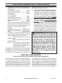
Conned and Unconned Space
The National Fuel Gas Code, ANSI Z223.1/
NFPA 54 denes a conned space as a space
whose volume is less than 50 cubic feet per
1,000 Btu/hr (4.8 m
3
per kw) of the aggregate
input rating of all appliances installed in that
space and an unconned space as a space
whose volume is not less than 50 cubic feet
per 1,000 Btu/hr (4.8 m
3
per kw) of the ag-
gregate input rating of all appliances installed
in that space. Rooms communicating directly
with the space in which the appliances are
installed*, through openings not furnished
with doors, are considered a part of the un-
conned space.
* Adjoining rooms are communicating only if
there are doorless passageways or ventilation
grills between them.

www.usaprocom.com
9200006-01A
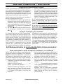
DETERMINING FRESH-AIR FLOW FOR HEATER LOCATION
4. Compare the maximum Btu/Hr the space
can support with the actual amount of Btu/
Hr used.
_______Btu/Hr (maximum can support)
_______Btu/Hr (actual amount used)
Example: 51,200 Btu/Hr (maximum the
space can support)
56,000 Btu/Hr (actual amount
of Btu/Hr used)
The space in the above example is a conned
space because the actual Btu/Hr used is more
than the maximum Btu/Hr the space can sup-
port. You must provide additional fresh air.
Your options are as follows:
A. Rework worksheet, adding the space
of an adjoining room. If the extra space
provides an unconned space, remove
door to adjoining room or add ventilation
grills between rooms. See Ventilation Air
From Inside Building, page 10.
B. Vent room directly to the outdoors. See
Ventilation Air From Outdoors, page 10.
C. Install a lower Btu/Hr heater, if lower Btu/
Hr size makes room unconned. If the ac-
tual Btu/Hr used is less than the maximum
Btu/Hr the space can support, the space
is an unconned space. You will need no
additional fresh air ventilation.
WARNING: If the area in which
the heater may be operated is
smaller than that dened as
an unconned space or if the
building is of unusually tight
construction, provide adequate
combustion and ventilation air
by one of the methods described
in the National Fuel Gas Code,
ANSI Z223.1/NFPA 54, the In-
ternational Fuel Gas Code, or
applicable local codes.
AIR FOR COMBUSTION AND VENTILATION
30,000
26,000
56,000
Determining if You Have a Conned
or Unconned Space
Use this work sheet to determine if you have
a conned or unconned space.
Space: Includes the room in which you will
install heater plus any adjoining rooms with
doorless passageways or ventilation grills
between the rooms.
1. Determine the volume of the space (length
x width x height).
Length x Width x Height =__________cu.
ft. (volume of space)
Example: Space size 20 ft. (6.1 m)
(length) x 16 ft. (4.88 m) (width) x
8 ft. (2.44 m) (ceiling height) = 2560 cu.
ft. (72.49 m
3
) (volume of space)
If additional ventilation to adjoining room
is supplied with grills or openings, add the
volume of these rooms to the total volume
of the space.
2. Multiply the space volume by 20 to deter-
mine the maximum Btu/Hr the space can
support.
________(volume of space) x 20 =
(Maximum Btu/Hr the space can support)
Example: 2560 cu. ft. (72.49 m
3
) (volume
of space) x 20 = 51,200 (maximum Btu/
Hr the space can support)
3. Add the Btu/Hr of all fuel burning appli-
ances in the space.
Vent-free heater _________ Btu/Hr
Gas water heater* _________ Btu/Hr
Gas furnace _________ Btu/Hr
Vented gas heater _________ Btu/Hr
Gas replace logs _________ Btu/Hr
Other gas appliances*+ _______ Btu/Hr
Total = ________ Btu/Hr
* Do not include direct-vent gas appli-
ances. Direct-vent draws combustion
air from the outdoors and vents to the
outdoors.
Example:
Gas water heater __________ Btu/Hr
Vent-free heater + _________ Btu/Hr
Total = _________ Btu/Hr

www.usaprocom.com
200006-01A10
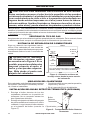
VENTILATION AIR
Ventilation Air From Inside Building
AIR FOR COMBUSTION AND VENTILATION
Outlet
Air
Ventilated
Attic
Outlet
Air
Inlet
Air
Inlet Air
Ventilated
Crawl Space
To
Crawl
Space
To Attic
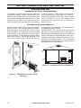
Figure 2 - Ventilation Air from Inside
Building
Figure 3 - Ventilation Air from Outdoors
Or
Remove
Door into
Adjoining
Room,
Option 3
Ventilation Grills
Into Adjoining Room,
Option 2
12"
12"
Ventilation
Grills
into Adjoining
Room,
Option 1
FAN
HOT
This fresh air would come from an adjoining
unconned space. When ventilating to an
adjoining unconned space, you must provide
two permanent openings: one within 12" of the
ceiling and one within 12" of the oor on the
wall connecting the two spaces (see options
1 and 2, Figure 2). You can also remove door
into adjoining room (see option 3, Figure 2).
Follow the National Fuel Gas Code, ANSI
Z223.1/NFPA 54, Air for Combustion and
Ventilation for required size of ventilation
grills or ducts.
Ventilation Air From Outdoors
Provide extra fresh air by using ventilation
grills or ducts. You must provide two perma-
nent openings: one within 12" of the ceiling
and one within 12" of the oor. Connect these
items directly to the outdoors or spaces open
to the outdoors. These spaces include attics
and crawl spaces. Follow the National Fuel
Gas Code, ANSI Z223.1/NFPA 54, Air for
Combustion and Ventilation for required size
of ventilation grills or ducts.
IMPORTANT: Do not provide openings
for inlet or outlet air into attic if attic has a
thermostat-controlled power vent. Heated air
entering the attic will activate the power vent.
Rework worksheet, adding the space of the
adjoining unconned space. The combined
spaces must have enough fresh air to supply
all appliances in both spaces.

www.usaprocom.com
11200006-01A
INSTALLATION
NOTICE: This heater is intended
for use as supplemental heat.
Use this heater along with your
primary heating system. Do not
install this heater as your pri-
mary heat source. If you have a
central heating system, you may
run system’s circulating blower
while using heater. This will help
circulate the heat throughout the
house. In the event of a power
outage, you can use this heater
as your primary heat source.
WARNING: A qualied ser-
vice person must install heater.
Follow all local codes.
WARNING: Never install the
heater
• in a bedroom or bathroom
• in a recreational vehicle
• where curtains, furniture,
clothing, or other ammable
objects are less than 36" from
the front, top, or sides of the
heater
• in high trafc areas
• in windy or drafty areas
CAUTION: This heater cre-
ates warm air currents. These
currents move heat to wall sur-
faces next to heater. Installing
heater next to vinyl or cloth wall
coverings or operating heater
where impurities (such as to-
bacco smoke, aromatic candles,
cleaning uids, oil or kerosene
lamps, etc.) in the air exist, may
cause walls to discolor.
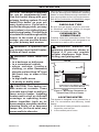
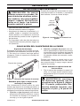
Figure 4 - Mounting Clearances as
Viewed From Front of Heater
IMPORTANT: Vent-free heaters add moisture
to the air. Although this is benecial, installing
heater in rooms without enough ventilation air
may cause mildew to form too much moisture.
See Air for Combustion and Ventilation, pages
8 through 10.
CHECK GAS TYPE
Be sure your gas supply is right for your heat-
er. Otherwise, call dealer where you bought
the heater for proper type heater.
CLEARANCES TO
COMBUSTIBLES
Carefully follow the instructions below. This
heater is a freestanding unit designed to be
mounted on a wall or set on a base.
WARNING: Maintain the
minimum clearances shown in
Figure 4. If you can, provide
greater clearances from oor,
ceiling, and joining wall.
CEILING
48"
Minimum
12"
Minimum
From
Sides of
Heater
Left
Side
Right
Side
5" Minimum to Top Surface of Carpeting,
Tile or Other Combustible Material
FLOOR
LOCATING HEATER
This heater is designed to be mounted on a
wall. For convenience and efciency, install
heater:
1. Where there is easy access for operation,
inspection, and service.
2. In the coldest part of room.

www.usaprocom.com
200006-01A12
FAN
HOT
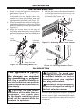
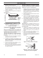
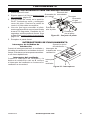
Figure 7 - Mounting Bracket Location
Figure 5 - Moving Thermostat Sensing
Bulb
INSTALLATION
Methods For Attaching Mounting
Bracket To Wall
Use only the last hole on each end of mounting
bracket to attach bracket to wall. Attach mount-
ing bracket to a wall only in one of two ways:
1.
Attaching to wall stud: This method provides
the strongest hold. Insert mounting screws
through mounting bracket and into wall studs.
2. Attaching to wall anchor: This method
allows you to attach mounting bracket to
hollow walls (wall areas between studs)
or to solid walls (concrete or masonry).
Decide which method better suits your needs.
Either method will provide a secure hold for
the mounting bracket.
Marking Screw Locations
1. Tape mounting bracket to wall where
heater will be located. Make sure mount-
ing bracket is level.
Bulb Clip
Thermostat
Sensing
Bulb
Mounting
Bracket
NG
NG
Mounting Bracket
The mounting bracket is located on back panel
of heater (see Figure 7). It has been taped
there for shipping. Remove mounting bracket
from back panel.
1. Pull out the sensing bulb from the two clips
located in the shipping position. There is
no need to take out the two bulb clips.
2. Take out the bulb clip from the hardware
package and insert it into the square hole.
Then insert the sensing bulb into the bulb
clip (see Figure 5).
FASTENING HEATER TO WALL
INSTALLING THERMOSTAT SENSING BULB (OPTIONAL)
BATTERY INSTRUCTIONS
CAUTION: Do not mix old and
new batteries. Do not mix alkaline,
standard (carbon - zinc), or re-
chargeable (nickel - cadmium) bat-
teries. Do not dispose of batteries in
re, batteries may explode or leak.
• Batteries are included.
• Remove batteries when depleted.
• Be sure to observe proper polarity (+/-)
when installing or replacing the batteries.
Damage due to improper battery installation
may void the warranty on the product.
• For long periods of non-operation, remove
batteries from all components for safety.
Unscrew ignitor cap and install a AAA battery
with the + pointing out. Replace cap.
Figure 6 - Installing Battery in Ignitor
AAA
Battery
Positive
UP

www.usaprocom.com
13200006-01A
FAN
HOT
INSTALLATION
11
1
/
10
"
Min.
16
1
/
16
"
12
3
/
4
"
Min.
Only Insert Mounting
Screws Through Last
Hole On Each End
Floor
Adjoining Wall
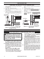
Figure 8 - Mounting Bracket Clearances
Figure 11 - Mounting Heater Onto
Mounting Bracket
Mounting Bracket
(attached to wall)
Horizontal
Slots
Stand-Out
Tab
Figure 9 - Folding Anchor
Figure 10 - Popping Open Anchor Wings
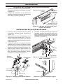
For Thin Walls
Attaching Mounting Bracket To Wall
Note: Wall anchors, mounting screws, and
spacers are in hardware package. The hard-
ware package is provided with heater.
Attaching to Wall Stud Method
For attaching mounting bracket to wall studs:
1. Drill holes at marked locations using 9/64"
drill bit.
2. Place mounting bracket onto wall. Line
up last hole on each end of bracket with
holes drilled in wall.
3. Insert mounting screws through bracket
and into wall studs.
4. Tighten screws until mounting bracket is
rmly fastened to wall studs.
Attaching to Wall Anchor Method
For attaching mounting bracket to hollow
walls (wall areas between studs) or solid walls
(concrete or masonry):
1. Drill holes at marked locations using
5/16" drill bit. For solid walls (concrete or
masonry), drill at least 1" deep.
2. Fold wall anchor as shown in Figure 9.
WARNING: Maintain mini-
mum clearances shown in Figure
4, page 11. If you can, provide
greater clearances from oor
and joining wall.
2.
Mark screw locations on wall (see Fig-
ure 8).
Note: Mark only last hole on each
end of mounting bracket. Insert mounting
screws through these holes only.
3. Remove tape and mounting bracket from
wall.
Placing Heater On Mounting
Bracket
1. Locate two horizontal slots on back panel
of heater (see Figure 11).
2. Place heater onto mounting bracket. Slide
horizontal slots onto stand-out tabs on
mounting bracket.
3. Insert wall anchor (wings rst) into hole.
Tap anchor ush to wall.
4. For thin walls (1/2" or less), insert red key
into wall anchor. Push red key to “pop”
open anchor wings (see Figure 10).
IMPORTANT: Do not hammer anchor key! For
thick walls (over 1/2" thick) or solid walls, do
not pop open wings.
5. Place mounting bracket onto wall. Line up
last hole on each end of bracket with wall
anchors.
6. Insert mounting screws through bracket
and into wall anchors.
7. Tighten screws until mounting bracket is
rmly fastened to wall.

www.usaprocom.com
200006-01A14
NG
LP
NG
LP
FAN
HOT
NG
LP
NG
LP
INSTALLATION
Figure 12 - Assembling Base Feet
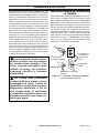
Figure 13 - Attaching Base Feet to Heater
Figure 14 - Securing Heater to Floor
Foot
Columns
Leg
Bracket
Base Cut Out
Screw
Hole
Screw
Screw
Finished
Assembly
INSTALLING BASE FEET
5. Position the heater to the desired location.
Secure the base feet to the oor by us-
ing two Phillips head self tapping screws
(provided) (see Figure 14).
GAS SELECTION
This appliance is factory
preset for propane/LP gas.
No changes are required
for connecting to propane/
L P. Only a qualied installer or
service technician can perform
gas selection and connecting to
gas supply.
CAUTION: Two gas line in-
stallations at the same time are
prohibited. The access plate
to the simple switching means
shall not be opened while the
heater is in operation.
CAUTION: To avoid gas
leakage at the inlet of regulator,
a qualied installer or service
technician must use supplied
hex plug with sealant.
WARNING: Do not attempt to
access or change the setting of
the fuel selection means.
Access to and adjustment of the fuel selection
means must only be performed by a qualied
service person when connecting this appli-
ance to a specied fuel supply at the time of
installation.
1. Snap the left and right foot columns to-
gether (see Figure 12).
2. Place the column assembly in the center
of the base cut out. Fasten column as-
sembly by using two Phillips head self
taping screws (provided) (see Figure 12).
3. Place leg bracket on the top of column as-
sembly and fasten it by using two Phillips
head self tapping screws (provided) (see
Figure 11).
4. Align four screw holes to the base of
the heater and attach it by using Phillips
head self tapping screws (provided) (see
Figure 13).

www.usaprocom.com
15200006-01A
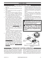
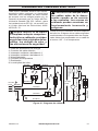
CONNECTING TO GAS SUPPLY
WARNING: A qualied ser-
vice technician must connect
heater to gas supply. Follow all
local codes.
WARNING: This appliance
requires a 3/8" NPT (National
Pipe Thread) inlet connection to
the pressure regulator.
WARNING: For natural gas,
Never connect heater to private
(non-utility) gas wells. This gas
is commonly known as wellhead
gas.
WARNING: Do not over-
tighten gas connections.
Change of the selector setting to other than
the fuel type specied at the time of installa-
tion could damage this appliance and render
it inoperable.
The installer shall replace the access cover
before completing the installation and operat-
ing this appliance.
For changing from propane to
natural gas supply:
1. Remove top screw from cover plate lo-
cated on back of heater (see Figure 15).
Rotate to expose fuel selection device.
2. For NATURAL GAS, press knob using a
at screwdriver with a blade with thick-
ness of a quarter and turn knob clockwise
until the knob locks into the NG
position (see Figure 15). Fuel selection
device must be locked in the NG position.
Do not operate heater between locked
positions!
3. Rotate and close cover over fuel selection
device and reinstall screw.
4. Remove hex plug (with wrench provided)
from natural gas inlet of regulator (see
Figure 15). Install hex plug into LP inlet
of regulator. Install gas line into NG inlet
of regulator. Use thread sealant to ensure
that there are no leaks.
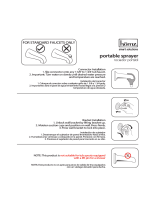
For changing from natural gas
supply to propane supply:
1. Remove top screw from cover plate lo-
cated on back of heater (see Figure 16).
Rotate to expose fuel selection device.
2. For propane gas, press in knob using a at
screwdriver with a blade the thickness of
a quarter and turn knob counterclockwise
until the knob locks into the LP posi-
tion (see Figure 16). Fuel selection device
must be locked in the LP position. Do not
operate heater between locked positions!
3. Rotate and close cover over fuel selection
device and reinstall screw.
4. Remove hex plug (with wrench provided)
from propane/LP inlet of regulator (see
Figure 16). Install hex plug into NG inlet
of regulator. Install gas line into propane/
LP inlet of regulator. Use thread sealant
to assure there are no leaks.
INSTALLATION
NG
LP
INLET GAS PRESSURE
MAX 1/2 PSIG (3.5 KPA)
Gas Inlet
Gas esté
Bottom of Heater
Back of Heater
NG
LP
Fuel
Selector
Knob
Hex Plug
Figure 16 - Settings for Propane/LP Gas
Selection
Gas Connection Fitting
NG
LP
INLET GAS PRESSURE
MAX 1/2 PSIG (3.5 KPA)
Gas Inlet
Gas esté
Bottom of Heater
Back of Heater
NG
LP
Fuel
Selector
Knob
Hex Plug
Figure 15 - Settings for Natural Gas
Selection
Gas
Connection
Fitting

www.usaprocom.com
200006-01A16
INSTALLATION
CAUTION: Use only new,
black iron or steel pipe. Inter-
nally tinned copper tubing may
be used in certain areas. Check
your local codes. Use pipe of
1/2" diameter or greater to allow
proper gas volume to heater. If
pipe is too small, undue loss of
pressure will occur.
CAUTION: For natural gas,
check your gas line pressure
before connecting heater to gas
line. Gas line pressure must be
no greater than 10.5" of water. If
gas line pressure is higher, heater
regulator damage could occur.
CAUTION: For propane/LP
gas, Never connect heater directly
to the gas supply. This heater
requires an external regulator
(not supplied). Install the external
regulator between the heater and
gas supply. Gas supplier provides
external regulator for natural gas.
The installer provides the external
regulator for propane/LP gas.
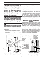
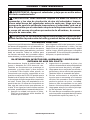
Figure 17 - Gas Connection
* Purchase the optional CSA design-certied equipment
shutoff valve from your dealer.
CAUTION: Avoid damage to
regulator. Hold gas regulator
with wrench when connecting
into gas piping and/or ttings.
CAUTION: Use pipe joint
sealant that is resistant to gas
(Propane/LP or Natural Gas).
Before installing heater, make sure you have
the items listed below:
• piping (check local codes)
• sealant (resistant to natural gas and pro-
pane/LP gas)
• equipment shutoff valve*
• test gauge connection*
• sediment trap
• tee joint
• pipe wrench
• exible gas hose (check local codes)
* A CSA design-certied equipment shutoff
valve with 1/8" NPT tap is an acceptable al-
ternative to test gauge connection. Purchase
the optional CSA design certied equipment
shutoff valve from your dealer.
Typical Inlet Pipe Diameters
Use 3/8" black iron pipe or greater. Installa-
tion must include an equipment shutoff valve,
union, and plugged 1/8" NPT tap. Locate
NPT tap within reach for test gauge hook up.
NPT tap must be upstream from heater (see
Figure 17).
Figure 18 - External Regulator
with Vent Pointing Down
External
Regulator with
Vent Pointing
Down
Propane/LP
Supply Tank
Equipment
Shutoff Valve
Ground
Joint Union
3/8" NPT
Pipe Nipple
Tee Joint
Reducer
Bushing to
1/8" NPT
1/8" NPT
Plug Tap
Test Gauge
Connection*
Sediment
Trap
Tee Joint
Pipe Nipple
Gap
3" Minimum
Natural Gas
From Gas Meter (5"
W.C.** to 10.5" W.C.
Pressure)
Propane/LP
From External
Regulator (11"
W.C.** to 14" W.C.
Pressure)

www.usaprocom.com
17200006-01A
Figure 19 - Equipment Shutoff Valve
CHECKING GAS CONNECTIONS
Open
Closed
Equipment
Shutoff Valve
1. Disconnect heater with its appliance main
gas valve (control valve) and equipment
shutoff valve from gas supply piping sys-
tem. Pressures in excess of 1/2 PSIG will
damage heater regulator.
2. Cap off open end of gas pipe where equip-
ment shutoff valve was connected.
3. Pressurize supply piping system by either
using compressed air or opening gas sup-
ply valve.
INSTALLATION
WARNING: Test all gas piping
and connections for leaks after
installing or servicing. Correct
all leaks at once.
WARNING: Never use an open
ame to check for a leak. Apply a
noncorrosive leak detection uid
to all joints. If bubbles form, there
is a leak. Correct all leaks at once.
PRESSURE TESTING GAS SUPPLY PIPING SYSTEM
Test Pressures In Excess Of 1/2 PSIG (3.5 kPa)
4. Check all joints of gas supply piping
system. Apply mixture of liquid soap and
water to gas joints. If bubbles form, there
may be a leak.
5. Correct all leaks at once.
6. Reconnect heater and equipment shutoff
valve to gas supply. Check reconnected
ttings for leaks.
Test Pressures Equal To or Less Than 1/2 PSIG (3.5 kPa)
1. Close equipment shutoff valve (see Fig-
ure 19).
2. Pressurize supply piping system by either
using compressed air or opening gas sup-
ply valve.
3. Check all joints from gas supply (see
Figure 20 or 21, page 18) to equipment
shutoff valve. Apply a noncorrosive leak
detection uid to all joints. Bubbles form-
ing show a leak.
4. Correct all leaks at once.
IMPORTANT: Install an equipment shutoff
valve in an accessible location. The equip-
ment shutoff valve is for turning on or shutting
off the gas to the appliance.
Apply pipe joint sealant lightly to male threads.
This will prevent excess sealant from going
into pipe. Excess sealant in pipe could result
in clogged heater valves.
The installer must supply an external regula-
tor. The external regulator will reduce incom-
ing gas pressure. You must reduce incoming
gas pressure to between 11" and 14" of water.
If you do not reduce incoming gas pressure,
heater regulator damage could occur. Install
external regulator with the vent pointing down
as shown in Figure 18, page 16. Pointing
the vent down protects it from freezing rain
or sleet.
Install sediment trap in supply line as shown
in Figure 17, page 16. Place sediment trap
where it is within reach for cleaning. Place
sediment trap where trapped matter is not
likely to freeze. A sediment trap traps mois-
ture and contaminants. This keeps them from
going into heater controls. If sediment trap is
not installed or is installed wrong, heater may
not run properly.

www.usaprocom.com
200006-01A18
OPERATION
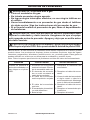
FOR YOUR SAFETY READ BEFORE LIGHTING
WARNING: If you do not fol-
low these instructions exactly, a
re or explosion may result caus-
ing property damage, personal
injury or loss of life.
A. This appliance has a pilot which must
be lighted by hand. When lighting the
pilot, follow these instructions exactly.
B. BEFORE LIGHTING smell all around
the appliance area for gas. Be sure to
smell next to the oor because some
gas is heavier than air and will settle
on the oor.
WHAT TO DO IF YOU SMELL GAS
• Do not try to light any appliance.
• Do not touch any electric switch; do
not use any phone in your building.
• Immediately call your gas supplier
from a neighbor’s phone. Follow the
gas supplier’s instructions.
• If you cannot reach your gas supplier,
call the re department.
C. Use only your hand to push in or turn
the gas control knob. Never use tools.
If the knob will not push in or turn
by hand, don’t try to repair it, call a
qualied service technician. Force or
attempted repair may result in a re or
explosion.
D. Do not use this appliance if any part
has been under water. Immediately call
a qualied service technician to inspect
the appliance and to replace any part of
the control system and any gas control
which has been under water.
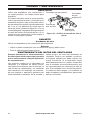
PRESSURE TESTING HEATER GAS CONNECTIONS
INSTALLATION
uid to all joints. Bubbles forming show a
leak.
5. Correct all leaks at once.
6. Light heater (see Lighting Instructions on
page 19). Check all other internal joints
for leaks.
7. Turn off heater (see To Turn Off Gas Ap-
pliance, page 20).
1. Open equipment shutoff valve (see Figure
19, page 17).
2. Open gas supply tank valve.
3. Make sure control knob of heater is in the
OFF position.
4. Check all joints from equipment shutoff
valve to control valve (see Figure 20 or
21). Apply a noncorrosive leak detection
Gas Valve
Gas Valve
Equipment
Shutoff Valve
Equipment
Shutoff Valve
Propane/LP
Supply Tank
Figure 20 - Checking Gas Joints for
Propane/LP Gas
Figure 21 - Checking Gas Joints for
Natural Gas
Gas Meter

www.usaprocom.com
19200006-01A
O
F
F
P
I
L
O
T
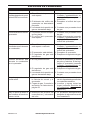
1. STOP! Read the safety information,
page 18.
2. Make sure equipment shutoff valve is fully
open.
3. Turn control knob clockwise to the
OFF position.
4. Wait ve (5) minutes to clear out any air.
Then smell for gas, including near the
oor. If you smell gas, STOP! Follow "B"
in the safety information, page 18. If you
do not smell gas, go to the next step.
5. Turn control knob counterclockwise
to the PILOT position. Press in control
knob for ve (5) seconds (see Figure 22).
Note: The rst time that the heater is oper-
ated after connecting the gas supply,the
control knob should be pressed for about
thirty (30) seconds. This will allow air to
bleed from the gas system. If pilot does
not stay lit, refer to Troubleshooting, pages
25 though 27. Also contact a qualied
service technician or gas supplier for
repairs. Until repairs are made, light pilot
with match.
• If control knob does not pop up when
released, contact a qualified service
technician or gas supplier for repairs.
6. With control knob pressed in, push
down and release ignitor button. This
will light pilot. The pilot is attached to
the front of burner. The pilot can be
seen through the grill. If needed, keep
pressing ignitor button until pilot lights.
Note: If pilot does not stay lit, refer to
Troubleshooting, pages 25 though 27.
Also contact a qualied service technician
or gas supplier for repairs. Until repairs
are made, light pilot with match. To light
pilot with match, see Manual Lighting
Procedure, page 20.
LIGHTING INSTRUCTIONS
Figure 22 - Control Knob in the OFF
Position
Ignitor
Button
Control Knob
7. Keep control knob pressed in for 30 sec-
onds after lighting pilot. After 30 seconds,
release control knob. If control knob does
not pop up when released, contact a quali-
ed service technician or gas supplier for
repairs.
Note: If pilot goes out, repeat steps 2
through 6. This heater has a safety inter-
lock system. Wait one (1) minute before
lighting pilot again.
8. Turn control knob counterclockwise
to desired heating level. The main burner
should light. Set control knob to any heat
level between 1 and 5.
CAUTION: Do not try to ad-
just heating levels by using the
equipment shutoff valve.
WARNING: If input gas
type is NG, make sure NG pilot
burner ignites. If input gas type
is LP, make sure LP pilot burner
ignites.
OPERATION
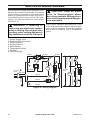
THERMOSTAT CONTROL OPERATION
The thermostatic control used on this model
differs from standard thermostats. Standard
thermostats simply turn the burner on and off.
The thermostat used on this heater senses the
room temperature. At times the room may ex-
ceed the set temperature. If so, the burner will
shut off. The burner will cycle back on when
room temperature drops below the set tem-
perature. The control knob can be set to any
comfort level between HIGH (5) and LOW (1).

www.usaprocom.com
200006-01A20
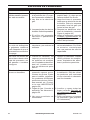
Figure 24 - Switches
SWITCHES OPERATION
Heating Coil Switch
When the switch is on I, the blower and heat-
ing coil turn on at the same time. It makes the
room temperature rises rapidly.
Blower Switch
When the blower and heating coil switch is
on O, turn the blower switch to I then the
blower turns on.
OFF
OFF
ON
ON
Blower
Switch
Heating
Coil Switch
Heating
Working
Light
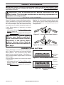
TO TURN OFF GAS TO APPLIANCE
Shutting Off Heater
Turn control knob clockwise to the
OFF position.
Shutting Off Burner Only (pilot
stays lit )
Turn control knob clockwise to the
PILOT position.
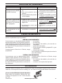
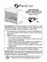
MANUAL LIGHTING PROCEDURE
1. Remove front panel.
2. Follow steps 2 through 5 under Lighting
Instructions, page 19.
3. With control knob pressed in, strike match.
Hold match to pilot until pilot lights.
4. Keep control knob pressed in for 30 sec-
onds after lighting pilot. After 30 seconds,
release control knob. Follow step 9 under
Lighting Instructions, page 19.
5. Replace front panel.
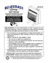
Figure 23 - Pilot Assembly
Pilot Air
Inlet Hole
Natural
Gas
Burner
Propane/LP
Gas Burner
Ignitor
Electrode
Thermocouple
Pilot Air Inlet Hole
OPERATION
Page is loading ...
Page is loading ...
Page is loading ...
Page is loading ...
Page is loading ...
Page is loading ...
Page is loading ...
Page is loading ...
Page is loading ...
Page is loading ...
Page is loading ...
Page is loading ...
Page is loading ...
Page is loading ...
Page is loading ...
Page is loading ...
Page is loading ...
Page is loading ...
Page is loading ...
Page is loading ...
Page is loading ...
Page is loading ...
Page is loading ...
Page is loading ...
Page is loading ...
Page is loading ...
Page is loading ...
Page is loading ...
Page is loading ...
Page is loading ...
Page is loading ...
Page is loading ...
Page is loading ...
Page is loading ...
Page is loading ...
Page is loading ...
Page is loading ...
Page is loading ...
Page is loading ...
Page is loading ...
Page is loading ...
Page is loading ...
Page is loading ...
Page is loading ...
Page is loading ...
Page is loading ...
Page is loading ...
Page is loading ...
-
 1
1
-
 2
2
-
 3
3
-
 4
4
-
 5
5
-
 6
6
-
 7
7
-
 8
8
-
 9
9
-
 10
10
-
 11
11
-
 12
12
-
 13
13
-
 14
14
-
 15
15
-
 16
16
-
 17
17
-
 18
18
-
 19
19
-
 20
20
-
 21
21
-
 22
22
-
 23
23
-
 24
24
-
 25
25
-
 26
26
-
 27
27
-
 28
28
-
 29
29
-
 30
30
-
 31
31
-
 32
32
-
 33
33
-
 34
34
-
 35
35
-
 36
36
-
 37
37
-
 38
38
-
 39
39
-
 40
40
-
 41
41
-
 42
42
-
 43
43
-
 44
44
-
 45
45
-
 46
46
-
 47
47
-
 48
48
-
 49
49
-
 50
50
-
 51
51
-
 52
52
-
 53
53
-
 54
54
-
 55
55
-
 56
56
-
 57
57
-
 58
58
-
 59
59
-
 60
60
-
 61
61
-
 62
62
-
 63
63
-
 64
64
-
 65
65
-
 66
66
-
 67
67
-
 68
68


ProCom Heating 120017 User manual
- Category
- Space heaters
- Type
- User manual
- This manual is also suitable for
Ask a question and I''ll find the answer in the document
Finding information in a document is now easier with AI
in other languages
Related papers
-
 ProCom Heating 120017 User manual
-
ProCom Heating MD3TPU User manual
-
 ProCom Heating ML150TPA Installation guide
-
 ProCom Heating MN180TPA User manual
-
 ProCom Heating MN100TBA User manual
-
 ProCom Heating ML060HPA User manual
-
 ProCom Heating PCD18T User manual
-
 ProCom Heating FBD28T-J-AS Installation guide
-
 ProCom Heating FBD400RTCC Installation guide
-
 ProCom Heating MTF4TPU User manual


Other documents
-
Procom FBD32RT User guide
-
 Utilitech 9008073046 Installation guide
-
 HOMZ 1523008 User manual
-
Reddy Heater IWH16NLTBDC User manual
-
 BLUEGRASS LIVING 200089 User manual
-
Black & Decker BDHF70-80 User guide
-
 DuraHeat EWH9600 User manual
-
Silvercrest 378331 Owner's manual
-
-
Aspes ACE1110B Owner's manual


