Page is loading ...

SAVE THIS MANUAL FOR FUTURE REFERENCE
Owner’s Manual
For
Diesel Generator
MMG625VT2
003424
For technical assistance contact:
www.generacmobileproducts.com
Technical Support
1-800-926-9768

ii Owner’s Manual for MMG625VT2
Use this page to record important information about your Mobile Generator
Record the information found on your unit data label on
this page. See unit serial number location (Unit and
Serial Number Locations).
Engine and generator serial numbers are located on
separate data plates affixed to the engine and generator
respectively.
When contacting a Generac Mobile Products Authorized
Dealer about parts and service, always supply the
complete model number and serial number of the unit.
Operation and Maintenance: Proper maintenance and
care of the generator ensures a minimum number of
problems and keeps operating expenses at a minimum. It
is the operator’s responsibility to perform all safety
checks, to verify that all maintenance for safe operation is
performed promptly, and to have the equipment checked
periodically by a Generac Mobile Products Authorized
Dealer. Normal maintenance, service and replacement of
parts are the responsibility of the owner/operator and, as
such, are not considered defects in materials or
workmanship within the terms of the warranty. Individual
operating habits and usage may contribute to the need
for additional maintenance or service.
Unit Model Number
Unit Serial Number
Engine Model
Number
Engine Serial
Number
Generator Model
Number
Generator Serial
Number
Date Purchased
(000004)
WARNING
California Proposition 65. Engine exhaust and some
of its constituents are known to the state of California
to cause cancer, birth defects, and other reproductive
harm.
(000005)
WARNING
California Proposition 65. This product contains or
emits chemicals known to the state of California to
cause cancer, birth defects, and other reproductive
harm.

Owner’s Manual for MMG625VT2 iii
Table of Contents
Introduction and Safety
Introduction .......................................................1
Read This Manual Thoroughly ..........................1
Safety Rules ......................................................1
General Hazards ...............................................2
Explosion and Fire Hazards ..............................2
Trailer Hazards ..................................................3
Electrical Hazards .............................................3
Battery Hazards ................................................4
General Information
Component Locations .......................................5
Unit and Serial Number Locations ....................6
Engine Oil Recommendations ...........................6
Coolant Recommendation .................................6
Control Panel ....................................................7
PowerZone® Controller ....................................8
Controller Features and Functions ....................9
Home Button .....................................................9
Close Generator Circuit Breaker (GCB)
Button ................................................................9
Open Generator Circuit Breaker (GCB)
Button ................................................................9
Alarm Mute Button ............................................9
AUTO and MANUAL Mode Buttons ..................9
Navigation Buttons ............................................9
Control Power Switch ........................................9
Engine Start Button ...........................................9
Engine STOP/RESET Button ............................9
Liquid Crystal Display (LCD) .............................9
Maintenance Screens .......................................9
Generator Summary ........................................10
Home Tab .......................................................10
Engine Tab ......................................................10
Generator Tab .................................................10
Bus Tab ...........................................................11
Alarms Tab ......................................................11
Input/Output Tab .............................................12
PLC Tab ..........................................................12
Schedule Tab ..................................................12
Status Tab .......................................................12
Controller Information Displays, Functions,
and Reset ........................................................12
Belt Tensioner .................................................12
Optional Equipment .........................................13
Shorting (Link) Board Option ..........................13
Operation
Prestart Checklist ............................................ 15
Manually Starting the Unit ............................... 15
AUTO (Remote) Starting the Unit ................... 16
Parallel Setup and Operation .......................... 16
Ladder Operation ............................................ 17
Door Latch Operation ..................................... 17
Viscous Fan Clutch ......................................... 18
Wet Stacking ................................................... 18
Engine Derating .............................................. 18
Cold Starting Operation .................................. 18
Generator Output Connections ....................... 19
Generator Cam Lock Connections ................. 19
Voltage Regulator ........................................... 20
Customer Convenience Receptacles ............. 20
Main Circuit Breaker ....................................... 21
Transfer Switch ............................................... 21
AUTO Exercise Timer ..................................... 22
Accessing the Configuration Menu .................22
Set the Controller Clock ..................................22
Set the Schedule .............................................22
Setting Up a Daily Scheduled Run ..................23
Set the Unit to AUTO Mode ............................23
Shutting Down the Unit ................................... 23
Emergency Stop Switch .................................. 23
Towing the Unit ............................................... 23
Lifting the Unit ................................................. 24
Maintenance
Emissions Information .................................... 25
Daily Walk Around Inspection ......................... 25
General Maintenance ..................................... 25
Basic Maintenance Schedule ......................... 25
Special Service Intervals .................................26
Engine Break-In Requirements ....................... 26
Resetting the Maintenance Alarms ................. 27
Checking Generator Drive Plate Torque ......... 27
Jack Maintenance ........................................... 27
Side-Wind Models ...........................................27
Top-Wind Models ............................................27
Trailer Wheel Bearings ................................... 28
Troubleshooting
General Troubleshooting ................................ 29

iv Owner’s Manual for MMG625VT2
Wiring Diagrams and Service Log
AC Wiring ........................................................31
AC Wiring - Control Panel Receptacles ..........32
AC Wiring - Link Board Option ........................33
DC Wiring ........................................................34
Engine and Power Wiring (1 of 2) ...................35
Engine and Power Wiring (2 of 2) ...................36
DC Wiring - Battery Charger ...........................37
DC Wiring - Engine Heater .............................38
DC Wiring - Remote Communication
(Optional) ........................................................39
Trailer Lights ...................................................40
Wiring Harness - Electric Brake ......................41
Paralleling - Plug Resistor ...............................42
Paralleling - Cable Assembly ..........................43
Service Log .....................................................44

Owner’s Manual for MMG625VT2 1
Introduction and Safety
Section 1 Introduction and Safety
Introduction
Thank you for purchasing a Generac Mobile Products
LLC product. This unit has been designed to provide
high-performance, efficient operation, and years of use
when maintained properly.
The information in this manual is accurate based on
products produced at the time of publication. The
manufacturer reserves the right to make technical
updates, corrections, and product revisions at any time
without notice.
Read This Manual Thoroughly
If any section of the manual is not understood, contact
your nearest Generac Mobile Products Authorized
Dealer, or contact Generac Mobile Products (GMP)
Customer Service at
1-800-926-9768, or
www.generacmobileproducts.com with any questions
or concerns.
The owner is responsible for proper maintenance and
safe use of the equipment. Before installing, operating, or
servicing this generator:
Save these instructions for future reference. This manual
contains important instructions for the generator that
should be followed during installation, operation and
maintenance of the generator and batteries. ALWAYS
supply this manual to any individual that will use this
machine.
Safety Rules
The manufacturer cannot anticipate every possible
circumstance that might involve a hazard. The warnings
in this manual, and on tags and decals affixed to the unit
are, therefore, not all inclusive. If using a procedure, work
method or operating technique that the manufacturer
does not specifically recommend, verify that it is safe for
others. Also make sure the procedure, work method or
operating technique utilized does not render the
equipment unsafe.
Throughout this publication, and on tags and decals
affixed to the unit, DANGER, WARNING, CAUTION and
NOTE blocks are used to alert personnel to special
instructions about a particular operation that may be
hazardous if performed incorrectly or carelessly. Observe
them carefully. Their definitions are as follows:
NOTE: Notes contain additional information important to
a procedure and will be found within the regular text of
this manual.
These safety warnings cannot eliminate the hazards that
they indicate. Common sense and strict compliance with
the special instructions while performing the action or
service are essential to preventing accidents.
(000100a)
WARNING
Consult Manual. Read and understand manual
completely before using product. Failure to
completely understand manual and product
could result in death or serious injury.
(000001)
DANGER
Indicates a hazardous situation which, if not avoided,
will result in death or serious injury.
(000002)
WARNING
Indicates a hazardous situation which, if not avoided,
could result in death or serious injury.
(000003)
CAUTION
Indicates a hazardous situation which, if not avoided,
could result in minor or moderate injury.

2 Owner’s Manual for MMG625VT2
Introduction and Safety
General Hazards
Explosion and Fire Hazards
Asphyxiation. Running engines produce
carbon monoxide, a colorless, odorless,
poisonous gas. Carbon monoxide, if not
avoided, will result in death or serious injury.
(000103)
DANGER
(000107)
WARNING
Hearing Loss. Hearing protection is
recommended when using this machine.
Failure to wear hearing protection could
result in permanant hearing loss.
(000111)
WARNING
Moving Parts. Keep clothing, hair, and
appendages away from moving parts. Failure
to do so could result in death or serious injury.
(000108)
WARNING
Hot Surfaces. When operating machine, do not
touch hot surfaces. Keep machine away from
combustibles during use. Hot surfaces
could result in severe burns or fire.
WARNING
In case of an emergency, press the emergency
stop button to stop the engine immediately.
Failure to do so could result in death or serious
injury.
(000298)
CAUTION
(000291)
Equipment damage. Do not attempt to start or operate
a unit in need of repair or scheduled maintenance.
Doing so could result in serious injury, death, or
equipment failure or damage.
WARNING
WARNING
Risk of injury. Do not operate or service this
machine if not fully alert. Fatigue can impair the
ability to service this equipment and could result
in death or serious injury.
(000215)
(000182)
WARNING
CAUTION
(000229)
Equipment or property damage. Do not block
air intake or restrict proper air flow. Doing so
could result in unsafe operation or damage
to unit.
(000105)
DANGER
Explosion and Fire. Fuel and vapors are
extremely flammable and explosive. Add fuel
in a well ventilated area. Keep fire and spark
away. Failure to do so will result in death
or serious injury.
WARNING
Fire risk. Fuel and vapors are extremely
flammable. Do not operate indoors. Doing so
could result in death, serious injury, or
property or equipment damage.
(000281)
(000147)
WARNING
Risk of Fire. Unit must be positioned in a
manner that prevents combustible material
accumulation underneath. Failure to do so
could result in death or serious injury.

Owner’s Manual for MMG625VT2 3
Introduction and Safety
Trailer Hazards Electrical Hazards
WARNING
Trailer must be securely coupled to the hitch
and chains correctly attached. Uncoupled or
unchained towing could result in death or serious
injury.
(000233)
WARNING
Do not operate this unit while transporting.
Doing so could result in death or serious
injury.
(000231)
(000234a)
WARNING
Crushing hazard. Verify unit is properly secured
and on level ground. An unsecured unit can
suddenly roll or move, causing death or serious
injury.
WARNING
Property or Equipment Damage. Tighten wheel lug
nuts after first 50 miles to factory specifications.
Failure to do so could result in death, serious injury,
property or equipment damage.
(000235)
(000145)
DANGER
Electrocution. In the event of electrical accident,
immediately shut power OFF. Use non-conductive
implements to free victim from live conductor. Apply
first aid and get medical help. Failure to do so will
result in death or serious injury.
(000104)
DANGER
Electrocution. Water contact with a power
source, if not avoided, will result in death
or serious injury.
(000144)
DANGER
Electrocution. Contact with bare wires,
terminals, and connections while generator
is running will result in death or serious injury.
(000152)
DANGER
Electrocution. Verify electrical system is
properly grounded before applying power.
Failure to do so will result in death or serious
injury.
(000123)
DANGER
Electrocution. Turn utility supply OFF before
working on utility connections of the transfer
switch. Failure to do so will result in
death or serious injury.
(000150)
DANGER
Electrocution. Never connect this unit to the electrical
system of any building unless a licensed electrician
has installed an approved transfer switch. Failure to
do so will result in death or serious injury.
(000164)
WARNING
Electrical shock. Disconnect battery ground
terminal before working on battery or battery
wires. Failure to do so could result in death
or serious injury.

4 Owner’s Manual for MMG625VT2
Introduction and Safety
Battery Hazards
Always recycle batteries in accordance with local laws
and regulations. Contact your local solid waste collection
site or recycling facility to obtain information on local
recycling processes. For more information on battery
recycling, visit the Battery Council International website
at: http://batterycouncil.org/.
(000188)
DANGER
Electrocution. Do not wear jewelry while
working on this equipment. Doing so will
result in death or serious injury.
(000137a)
WARNING
(000162)
WARNING
Explosion. Do not dispose of batteries in a fire.
Batteries are explosive. Electrolyte solution can cause
burns and blindness. If electrolyte contacts skin or eyes,
flush with water and seek immediate medical attention.
(000163a)
WARNING
Risk of burn. Do not open or mutilate batteries.
Batteries contain electrolyte solution which can
cause burns and blindness. If electrolyte contacts
skin or eyes, flush with water and seek immediate
medical attention.
WARNING
Environmental Hazard. Always recycle batteries at an
official recycling center in accordance with all local
laws and regulations. Failure to do so could result in
environmental damage, death or serious injury.
(000228)

Owner’s Manual for MMG625VT2 5
General Information
Section 2 General Information
Component Locations
Figure 2-1. Component Locations
Table 2-1. Generator Components
A
Engine
L
Lift Points
B
Generator Box
M
Oil Filter
C
Air Filter
N
12 Volt Batteries (2)
D
Generator
O
Roof Access Ladder
E
Steps
P
Receptacle Box
F
Fuel Filter (primary)
Q
Main Circuit Breaker
G
Fuel Filter (secondary)
R
Lug Box
H
Oil Dipstick
S
Emergency Stop Switch
I
Alternator
T
Control Box
J
Radiator
U
Starter
K
Exhaust Muffler
002867
C
K
B
A
O
H
I
F
J
P
E
G
L
M
N
Q
RS
T
D
U

6 Owner’s Manual for MMG625VT2
General Information
Unit and Serial Number Locations
See Figure 2-2 to locate the unit ID tag (A), located
above the controller behind the control door, and Vehicle
Identification Number (VIN) tag (B). Important
information, such as the unit model number, serial
number, VIN and tire loading information is found on
these tags. Record the information from these tags so it
is available if the tags are lost or damaged. When
ordering parts or requesting assistance, you may be
asked to provide this information.
Figure 2-2. Unit and Serial Number Locations
Engine Oil Recommendations
To maintain the product warranty, the engine oil should
be serviced in accordance with the recommendations of
this manual.
The engine has been filled with factory engine oil of a
grade recommended by the engine supplier.
See Figure 2-3. Use a high quality detergent oil with an
appropriate classification and viscosity for the engine
type and ambient temperature conditions. Consult your
Generac Mobile Products Authorized Dealer or the
applicable engine service manual for engine oil
recommendations.
Figure 2-3. Oil Recommendation
Coolant Recommendation
Consult your Generac Mobile Products Authorized
Dealer or the applicable engine service manual for
engine coolant recommendations. See table below for
mixtures:
* Maximum freeze protection is at 70%.
002866
A
B
ºC
-30 -20 -10 0 10 20 30 40
ºF
-22 -4 14 32 50 68 86 104
ºC
-30 -20 -10 0 10 20 30 40
ºF
-22 -4 14 32 50 68 86 104
SAE 15W/40
SAE 10W/30
SAE 5W/30
SAE 20W/30
SAE 30
SAE 40
004092
Freezing Point °F (°C)
-12
(-24)
-34
(-36)
-54
(-48)
-90
(-67)
Water (% Volume) 60 50 40 30
Anitfreeze (% Volume) 40 50 60 70*
(000149)
DANGER
Risk of poisoning. Do not use mouth to
siphon coolant. Doing so will result in
death or serious injury.
(000154)
WARNING
Risk of burns. Do not open coolant system
until engine has completely cooled.
Doing so could result in serious injury.
(000165)
CAUTION
Do not use any chromate base rust inhibitor with
propylene glycol base antifreeze, boosters or
additives. Doing so will cause overheating.

Owner’s Manual for MMG625VT2 7
General Information
Control Panel
Figure 2-4. Control Panel Component Locations
Table 2-2. Control Panel Components
A
Scene lighting right side switch (optional)
M
120V/15A Edison plug (1)
B
Scene lighting left side switch (optional)
N
30A circuit breaker
C
Interior lights switch
O
15A circuit breaker
D
Output ground connection
P
Emergency stop switch
E
Remote Start Terminal Block
Q
Paralleling CAN receptacles
F
20A circuit breakers (2)
R
Cam lock connectors
G
LED Light
S
Connection terminal lugs (4)
H
50A circuit breakers (3)
T
Generator circuit breaker (GCB)
I
LED ON/OFF Switch
U
PowerZone controller
J
240V twist-lock receptacles (3)
V
Control power switch
K
120V GFCI receptacles (2)
W
Engine idle switch
L
120V/30A Edison plug (1)
X
Fuel transfer switch
002844
A
C
D
F
H
J
K
L
P
R
S
T
X
W
B
V
U
M
E
G
I
N
O
Q

8 Owner’s Manual for MMG625VT2
General Information
PowerZone
®
Controller
The PowerZone Parallel controller is an AUTO start
controller that monitors the unit and indicates operational
status and fault conditions. The controller can be
programmed to automatically start or stop based on time
schedule, fault condition, or load demand.
The controller constantly monitors vital generator and
engine functions for a number of preprogrammed alarm
and fault conditions. When a fault condition occurs, the
engine can be shut down automatically and the display
screen will show the fault that caused the shut down. To
resume operation, the fault condition must be resolved.
The controller operates the Generator Circuit Breaker
(GCB) by sending an open or close signal to the breaker.
This is necessary for parallel operations, where the
generator and bus voltages need to be synchronized
prior to closing the breaker.
NOTE: If the breaker is opened or closed manually using
the push buttons on the GCB, the unit will shutdown; only
use the controller for GCB operation.
This controller also records a history of unit performance
which may be viewed at any time and will not be lost
when the controller is powered down.
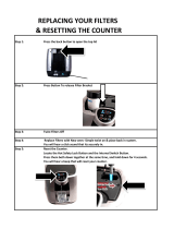
Figure 2-5. PowerZone Controller Layout
Table 2-3. Controller Features
A Navigation Buttons
B Engine Start Button
C Engine STOP/RESET button
D Display Screen
E MANUAL mode button
F AUTO mode Button
G Alarm Mute Button
H Open GCB Button
I Close GCB Button
J Home Button
003425
A
B
C
D
E
F
G
H
I
J

Owner’s Manual for MMG625VT2 9
General Information
Controller Features and Functions
Home Button
The Home ( ) button is the default screen of the
controller and will display after the controller is powered
up and the unit management software is loaded. It
displays a live readout of the kW meter, percent of load
used (gauge), selected phase, volts and amps being
produced by the generator, and the fuel level with time
until empty. The controller will automatically return to this
screen from any other screen after a period of inactivity.
Figure 2-6. Home Button Screen
Close Generator Circuit Breaker (GCB) Button
The Close GCB ( ) button closes the generator circuit
breaker (in MANUAL mode only).
Open Generator Circuit Breaker (GCB) Button
The Open GCB ( ) button opens the generator circuit
breaker (in MANUAL mode only).
Alarm Mute Button
The Alarm Mute ( ) button silences the audible alarm.
Additional action will be required to fully disable the
active alarm.
AUTO and MANUAL Mode Buttons
The AUTO and MANUAL Mode buttons change the
startup and shutdown mode of the unit. When the AUTO
Mode ( ) button is pressed, the unit enters AUTO
mode. When the MANUAL Mode ( ) button is pressed,
the unit enters MANUAL mode.
Navigation Buttons
These buttons are used to navigate and interact with the
PowerZone Parallel controller screens. Pressing any
directional arrow (▲, ►, ▼, ◄) while on any of the
operator screens will open the maintenance screens and
navigate the tabs and pages within the maintenance
screens. The Enter () button is used to select menus,
confirm alarms, and confirm altered settings.
Control Power Switch
Use this switch to start up and shut down the PowerZone
Parallel controller. This switch should not be turned OFF
when the unit is running.
Engine Start Button
Pressing the Engine Start (I) button while the controller is
in MANUAL mode will start the unit, provided there are
no shutdown errors and the engine satisfies the start
status. If the controller is in AUTO mode, the Engine Start
(I) button has no effect.
Engine STOP/RESET Button
Pressing the Engine STOP/RESET (O) button will shut
down the unit and put the controller into STOP mode,
whether in MANUAL mode or AUTO mode.
Liquid Crystal Display (LCD)
Displays the various operator and maintenance screens.
By viewing these screens, the operator will be able to
monitor both the engine and generator status while the
unit is running.
Maintenance Screens
All of the data inputs from the engine, generator, inputs/
outputs, schedule and PowerZone controller are visible
on the maintenance screens.
The information displayed on the maintenance screens
can be used to identify, diagnose and troubleshoot unit
shutdown conditions and poor unit performance. The
maintenance screens can be accessed from any
operator screen by pressing any directional arrow (▲, ►,
▼, ◄).
Manual Mode
3 PHASE
Volts
Amps
480
128
106.9 kW
%
0
10
100
110
20
30
40
50
60
70
80
90
Time to Empty
15 hr
Full
3/4
1/2
1/4
Empty
74
%
GEN
003426
WARNING
In case of an emergency, press the emergency
stop button to stop the engine immediately.
Failure to do so could result in death or serious
injury.
(000298)
CAUTION
(000246)
Equipment Damage. The emergency stop switch
is not to be used to power down the unit under
normal operating circumstances. Doing so will
result in equipment damage.

10 Owner’s Manual for MMG625VT2
General Information
The bottom of the screens have a list of available tabs,
with the currently displayed tab highlighted in blue. The
tabs can be selected by using the ► or ◄ buttons. To the
left of the tabs, the current/available pages are displayed.
The pages within a tab can be viewed by using the ▲
and ▼ buttons. Whenever a new tab is selected, the
current page will always be page one.
Generator Summary
The Generator Summary can be found at the top of all
maintenance screens and provides an overview of the
system.
Figure 2-7. Generator Summary Screen
Home Tab
The Home tab is automatically displayed when no other
page has been selected after a period of inactivity, or
when the operator selects the Home tab.
Figure 2-8. Home Tab Screen
Engine Tab
The Engine tab contains maintenance and
instrumentation data gathered from the engine. Above
the engine analogue meters is a row of alarm icons. Each
icon can be one of three colors: gray (inactive), yellow
(warning) or red (shutdown). The alarm icons are as
follows from left to right: water in fuel, charge alternator,
oil pressure, fuel level, battery voltage, coolant
temperature, ECU lamp and CAN link status.
NOTE: The content may change depending upon the
selected engine and the features supported by the
engine.
Figure 2-9. Engine Tab Screen
Generator Tab
The Generator tab contains maintenance and
instrumentation data gathered from the generator. Each
page highlights different data gathered by the generator,
with the analogue meters changing accordingly. The last
two pages will display the information in the bar graph. The
bar graph shows blue for positive and red for negative. For
the power factor bar graph, blue is for lagging pf and red
is for leading pf.
NOTE: The content may change depending upon the
selected generator and the features supported by the
generator.
Figure 2-10. Generator Tab Screen
SITE GENSET 8721-A1\8710
MSC ID. 1
Alternative Config 1
20:51
Generator Available
Total Total Energy Generator
0.0
0.0
0.0 60.0
0.0
0.0
0.0
0.0
0.0
0.0
0.0
7.5
8.0
0.9
kW
kVAr
Hz
%
%
%
%
Hz
kW
kVAr
kVA
----
pf kVArh
kVAh
kWh+
kW
kVAr
002846
SITE GENSET 8721-A1\8710
MSC ID. 1
Alternative Config 1
20:51
Generator Available
Total Total Energy Generator
Bus Generator
Home Engine Generator Bus Alarms I/O PLC Schedule Status
0.0
0.0
0.0 60.0
0.0
0.0
0.0
0.0
0.0
0.0
0.0
0.0
0.0
0.0
0.0
0.0
0
0
0
0
0
0
0000
120 120 120
207 208 208
0.0
0.0
0.0
0.0
7.5
8.0
0.9
1/1
kW
kVAr
Hz
%
%
%
%
Hz
kW
kVAr
kVA
----
pf kVArh
kVAh
kWh+
kW
kVAr
L1 L2 L3 L1 L2 L3
L1 L2 L3
kW
kVAr
kVA
----
pf
----
pf
----
pf
L1-L2 L2-L3 L3-L1 L1-L2 L2-L3 L3-L1
VVV
VVV
VVV
VVV
AAAA
I1 I2 I3 IE
002845
SITE GENSET 8721-A1\8710
MSC ID. 1
Alternative Config 1
20:51
Generator Available
Total Total Energy Generator
Home Engine Generator Bus Alarms I/O PLC Schedule Status
0.0
0.0
0.0 60.0
0.0
0.0
0.0
99999
1500
6
0
9
3
0.0
0.0
0.0
0.0
7.5
8.0
0.9
1/34
kW
kVAr
Hz
%
%
%
%
Hz
kW
kVAr
kVA
----
pf kVArh
kVAh
kWh+
kW
kVAr
Engine Starts
Fuel Used
99999999
Liters
RPM
15
21
12
18
27
33
24
30
36
0 0 0 0 0 2 5
‘
0
1
2
3
4
5
6
7
8
9
10
0.00
Bar
Oil press.
-50
0
50
100
150
200
250
0
ஂC
Coolant Temp.
0
10
50
0
%
Fuel Level
20
30
40 60
70
80
90
100
0
10
50
0
V
Charge Alt
20
30
40 60
70
80
90
100
0
10
50
0
V
Battery
20
30
40 60
70
80
90
100
-300
0
300
600
1200
1500
1800
0
ஂC
Oil Temp.
900
002847
SITE GENSET 8721-A1\8710
MSC ID. 1
Alternative Config 1
20:51
Generator Available
Total Total Energy Generator
Home Engine Generator Bus Alarms I/O PLC Schedule Status
0.0
0.0
0.0 60.0
0.0
0.0
0.0
0.0
0.0
0.0
0.0
7.5
8.0
0.9
1/34
kW
kVAr
Hz
%
%
%
%
Hz
kW
kVAr
kVA
----
pf kVArh
kVAh
kWh+
kW
kVAr
Freq
0
20
40
60
80
Hz
100
Volts
0
100
200
300
400
L3-L1
600
500
Volts
0
100
200
300
400
L2-L3
600
500
Volts
0
100
200
300
400
L1-L2
600
500
300
0
600
L1-L2
L2-L3
L3-L1
Volts
Volts Amps
KW
KVA KVAr
Pf
L1
L2
L3
IE
350
230
0
250
0
500
0
50.0
20.0
20.0
0.0
0.0
0.0
0.0
0.0
0.0
0.75
-0.25
1.00
Lead
Lag
Lead
002848

Owner’s Manual for MMG625VT2 11
General Information
Bus Tab
The Bus tab displays the voltage and frequency values of
the bus.
Figure 2-11. Bus Tab Screen
Alarms Tab
The Alarms tab displays warnings, electrical trip,
shutdown alarms and any engine Diagnostic Trouble
Codes (DTC) that are occurring or have occurred
previously. The first page on the Alarms tab displays the
alarms that are currently active. They are organized by
alarm type.
Figure 2-12. Alarms Tab Screen (Page One)
The second page of the Alarms tab shows the event log
with a list of events, including normal operation events
and alarm notifications, with the most recent events at
the top of the list. All indexed events include the date and
time of the event, hours of runtime on the engine when it
occurred, along with the event name or alarm type and
details.
Figure 2-13. Alarms Tab Screen (Page Two)
To scroll down within the event log, press the Enter ()
button. The scroll bar will change to blue, signifying it is
active. Press the ▲ or buttons to scroll up or down in
the event log. When finished, press the Enter () button
again.
SITE GENSET 8721-A1\8710
MSC ID. 1
Alternative Config 1
20:51
Generator AvailableTotal Total Energy Generator
Home Engine Generator Bus Alarms I/O PLC Schedule Status
0.0
0.0
0.0 60.0
0.0
0.0
0.0
0.0
0.0
0.0
0.0
7.5
8.0
0.9
1/34
kW
kVAr
Hz
%
%
%
%
Hz
kW
kVAr
kVA
----
pf kVArh
kVAh
kWh+
kW
kVAr
Freq
0
20
40 60
80
Hz
100
Volts
0
100
200
300
400
L3-L1
600
500
Volts
0
100
200
300
400
L2-L3
600
500
Volts
0
100
200
300
400
L1-L2
600
500
0
0
0
L1-L2
L2-L3
L3-L1
Volts Volts
L1
L2
L3
350
175
0
002849
SITE GENSET 8721-A1\8710
MSC ID. 1
Alternative Config 1
20:51
Generator AvailableTotal Total Energy Generator
Home Engine Generator Bus Alarms I/O PLC Schedule Status
0.0
0.0
0.0 60.0
0.0
0.0
0.0
0.0
0.0
0.0
0.0
7.5
8.0
0.9
1/34
kW
kVAr
Hz
%
%
%
%
Hz
kW
kVAr
kVA
----
pf kVArh
kVAh
kWh+
kW
kVAr
Warning
Shutdown Electrical Trip
Engine
002850
Table 2-4. Diagnostic Trouble Codes
Alarm Type
Color -
Background/
Text
Graphic
Warning Yellow/Black
Electrical Trip Purple/Black
Shutdown Red/Black
ECU Code Blue/White
Warning
Electrical Trip
Shutdown
Engine
SITE GENSET 8721-A1\8710
MSC ID. 1
Alternative Config 1
20:51
Generator Available
Total Total Energy Generator
Home Engine Generator Bus Alarms I/O PLC Schedule Status
0.0
0.0
0.0 60.0
0.0
0.0
0.0
0.0
0.0
0.0
0.0
7.5
8.0
0.9
1/34
kW
kVAr
Hz
%
%
%
%
Hz
kW
kVAr
kVA
----
pf kVArh
kVAh
kWh+
kW
kVAr
Warning
Shutdown
Shutdown
Shutdown
Shutdown
Shutdown
Shutdown
Shutdown
Shutdown
Shutdown
Shutdown
Shutdown
Shutdown
This is an event index 1
This is an event index 2
This is an event index 3
This is an event index 4
This is an event index 5
This is an event index 6
This is an event index 7
This is an event index 8
This is an event index 9
This is an event index 10
This is an event index 11
This is an event index 12
This is an event index 13
1 01/01/1970 00:00:01 0:00
2 02/06/1970 11:45:55 0:00
3 01/01/1970 00:00:00 0:00
4 01/01/1970 00:00:00 0:00
5 01/01/1970 00:00:00 0:00
6 01/01/1970 00:00:00 0:00
7 01/01/1970 00:00:00 0:00
8 01/01/1970 00:00:00 0:00
9 01/01/1970 00:00:00 0:00
10 01/01/1970 00:00:00 0:00
11
12 01/01/1970 00:00:00 0:00
13 01/01/1970 00:00:00 0:00
01/01/1970 00:00:00 0:00
Index Date Time Hrs Event Details
002851

12 Owner’s Manual for MMG625VT2
General Information
Input/Output Tab
The Input/Output (I/O) tab shows a list of digital inputs
and outputs connected to the controller, whether they are
active and the current state (open/closed status) of the
input and output.
Figure 2-14. Input/Output Tab Screen
PLC Tab
The PLC tab displays all the PLC counters and registers.
Figure 2-15. PLC Tab Screen
Schedule Tab
The Scheduler tab shows the current configuration and
status of the scheduler, located below the generator
summary. The maintenance configuration status and time
remaining until an alarm, electrical trip or shutdown will
be displayed at the bottom of the screen. The lamp(s) to
the left shows the configuration status of the
maintenance alarm, not the alarm condition.
Figure 2-16. Schedule Tab Screen
Status Tab
The Status tab contains the status and configuration of
the controller, firmware and data connections.
Figure 2-17. Status Tab Screen
Controller Information Displays,
Functions, and Reset
The PowerZone controller constantly monitors vital
generator and engine functions for a number of
operation, alarm and fault conditions. When a fault
condition occurs, the engine will shut down automatically
and the main display will show the fault that has caused
the shutdown. To resume operation, the fault condition
must be resolved. To reset the controller and resume
operation, press the Enter () button.
Belt Tensioner
The Volvo engine includes an automatic tensioner that
cannot be adjusted or repaired and is designed to
maintain proper tension over the belt’s life. Inspect units
according to the manufacturer’s specifications.
SITE GENSET 8721-A1\8710
MSC ID. 1
Alternative Config 1
20:51
Generator Available
Total Total Energy Generator
Home Engine Generator Bus Alarms I/O PLC Schedule Status
0.0
0.0
0.0 60.0
0.0
0.0
0.0
0.0
0.0
0.0
0.0
7.5
8.0
0.9
1/34
kW
kVAr
Hz
%
%
%
%
Hz
kW
kVAr
kVA
----
pf kVArh
kVAh
kWh+
kW
kVAr
Digital Inputs
Ip Description
A
B
C
D
E
F
H
I
J
G
K
Active State
Ip Description
Active State
002853
SITE GENSET 8721-A1\8710
MSC ID. 2
Default Config
13:36
Generator At Rest
Total Total Energy Generator
Home Engine Generator Bus Alarms I/O PLC Schedule Status
0.0
0.0
0.0 0.0
0.0
0.0
0.0
1
2
3
4
5
6
7
8
9
10
0
0
0
0
0
0
0
0
0
0
Counter 1
Counter 2
Counter 3
Counter 4
Counter 5
Counter 6
Counter 7
Counter 8
Counter 9
Counter 10
0.0
0.0
0.0
0.0
10806.2
10785.8
0.9
1/14
kW
kVAr
Hz
%
%
%
%
Hz
kW
kVAr
kVA
----
pf kVArh
kVAh
kWh+
kW
kVAr
PLC Counters
Index Description Counter
002854
SITE GENSET 8721-A1\8710
MSC ID. 1
Alternative Config 1
20:51
Generator AvailableTotal Total Energy Generator
Home Engine Generator Bus Alarms I/O PLC Schedule Status
0.0
0.0
0.0 60.0
0.0
0.0
0.0
0.0
0.0
0.0
0.0
7.5
8.0
0.9
1/34
kW
kVAr
Hz
%
%
%
%
Hz
kW
kVAr
kVA
----
pf kVArh
kVAh
kWh+
kW
kVAr
Warning
Warning
Warning
ActionDescriptionAlarm
Maintenance
Scheduler Disabled
Event
Week Day Start Stop Duration
Event
Week Day Start Stop Duration
9
10
11
12
13
14
15
16
First
1
2
3
4
5
6
7
8
Monday
00:00
00:00 00:00
First
Monday
00:00 00:00 00:00
First
Monday
00:00
00:00 00:00
First
Monday
00:00 00:00
00:00
First
Monday
00:00 00:00 00:00
First
Monday
00:00
00:00 00:00
First
Monday
00:00 00:00
00:00
First
Monday
00:00 00:00 00:00
First
Monday
00:00 00:00
00:00
First
Monday
00:00
00:00 00:00
First
Monday
00:00 00:00
00:00
First
Monday
00:00 00:00 00:00
First
Monday
00:00
00:00 00:00
First
Monday
00:00 00:00
00:00
First
Monday
00:00
00:00 00:00
First
Monday
00:00 00:00 00:00
Time (hh:mm)
Time (hh:mm)
1
00:00 01/01/1970
00:00
Hours Date
Time
Alarm string
2 00:00 01/01/1970 00:00 Alarm string
3
00:00
01/01/1970 00:00 Alarm string
Due
002852
SITE GENSET 8721-A1\8710
MSC ID. 1
Alternative Config 1
20:51
Generator AvailableTotal Total Energy Generator
Home Engine Generator Bus Alarms I/O PLC Schedule Status
0.0
0.0
0.0 60.0
0.0
0.0
0.0
0.0
0.0
0.0
0.0
7.5
8.0
0.9
1/34
kW
kVAr
Hz
%
%
%
%
Hz
kW
kVAr
kVA
----
pf kVArh
kVAh
kWh+
kW
kVAr
Link Quality 100%
Variant:
Application:
USB ID:
Bootloader:
8704
V0.0
123456
V0.0
RS232, 19k2 baud
About
Variant:
Application:
USB ID:
8701
V0.0
123456
Bootloader:
Analogue:
Engine:
V0.0
V0.0
V0.0
Status
Supervisor State:
Engine State:
Load State:
Protections:
A state machine state
A state machine state
A state machine state
A state machine state
002855

Owner’s Manual for MMG625VT2 13
General Information
Optional Equipment
Shorting (Link) Board Option
The output voltage can be changed by moving the
shorting (link) board in the generator reconnect box. The
reconnect box is located on the top of the generator.
Before attempting to change the output voltage, shut the
generator down and make sure that the generator circuit
breaker and the control power switch are in the OFF (O)
position/state.
To receive 480 3Ø voltage at the connection lugs, the
shorting (link) board must be attached in the lower
position as shown in the illustration. For 208 3Ø voltage,
the shorting (link) board must be in the upper position as
shown in the illustration. If the board needs to be
changed from one setting to the other, remove all of the
1/2 in. nuts that hold the shorting (link) board down and
move it to the new position. Replace all of the hardware
and tighten it to 25 ft-lbs. of torque. Reinstall the
reconnect box door and start the generator by following
the Prestart Checklist.
Figure 2-18. Shorting (Link) Board
DANGER
Electrocution. Lethal voltage may be present
at connection lugs. Do not change the voltage
while the engine is running. Doing so will
result in death or serious injury.
(000309)
Link Board Attached in
480 Volt 3Ø Position
L1
L-N
L2
N
L3
L-L
T1
T9
T11
T7
T10
T4
T12
T8
T3
T6
T2
T5
L1
L-N
L2
N
L3
L-L
T1
T9
T11
T7
T10
T4
T12
T8
T3
T6
T2
T5
Link Board Attached in
208 Volt 3Ø Position
Remove all
1/2” nuts

14 Owner’s Manual for MMG625VT2
General Information
This page intentionally left blank.

Owner’s Manual for MMG625VT2 15
Operation
Section 3 Operation
Prestart Checklist
Before starting the unit, all items in the prestart checklist
must be completed. This checklist applies to both manual
and remote starting of the unit.
• Verify all maintenance procedures are up to date.
For more information, see General Maintenance
and Basic Maintenance Schedule.
• The unit must be level.
• Verify there is no water inside, on, or near the unit;
dry if needed.
• For grounding requirements, follow any local, state,
or National Electrical Code (NEC) guidelines.
• Verify the Control Power switch is OFF (O).
• Verify all circuit breakers are OFF (O).
• Inspect all electrical cords; repair or replace any
that are cut, worn, or bare.
• Verify oil, coolant, and fuel levels are correct, per
the engine manufacturer manual.
• Verify battery connections are secure.
• Verify all electrical connections at the connection
lugs, if equipped, are tight and wired correctly.
• Turn the battery disconnect switch ON, if equipped.
• Inspect the engine fan belt tension and condition.
• Inspect the engine fan guard.
• Inspect the engine exhaust system for loose or
rusted components.
• Verify the radiator and surrounding shroud are
clear of debris.
• Verify all covers are in place and secure.
• Verify the emergency stop switch is pulled out.
Manually Starting the Unit
All units equipped with the PowerZone controller will
initially start up in STOP mode. Use the following
procedure to start the generator in MANUAL mode:
1. Move the Control Power switch to ON (I).
2. The display screen will show the prestart diagnosis
and the controller will load the unit management
software.
Figure 3-1. Prestart Screen
3. When the software is loaded, the Home screen will
be displayed and the controller will be in STOP
mode as indicated at the top of the screen. Press
the MANUAL Mode ( ) button to enter MANUAL
mode.
Figure 3-2. Home Screen
NOTE: The engine can be started from any screen when
it is in MANUAL mode.
4. Pressing the green Engine Start (I) button on the
controller will initiate the startup procedure and
start the engine, provided there are no engine
faults preventing the unit from starting.
NOTE: It may take a few seconds for the engine to run
smoothly and reach its governed operating speed. During
this time, the screen will show a voltage different from
that set with the voltage selector switch.
5. If the engine does not start after the first cranking
attempt, the engine will pause for 15 seconds to
allow the starter to cool. The display screen will
show MANUAL MODE - CRANK REST at the top
(000100a)
WARNING
Consult Manual. Read and understand manual
completely before using product. Failure to
completely understand manual and product
could result in death or serious injury.
Asphyxiation. Running engines produce
carbon monoxide, a colorless, odorless,
poisonous gas. Carbon monoxide, if not
avoided, will result in death or serious injury.
(000103)
DANGER
82%
Image File Transer...
®
002804
Stop Mode
3 PHASE
Volts
Amps
0
0
0.0 kW
%
0
10
100
110
20
30
40
50
60
70
80
90
Time to Empty
15 hr
Full
3/4
1/2
1/4
Empty
74
%
V
002805

16 Owner’s Manual for MMG625VT2
Operation
of the screen. The engine will make two more
attempts to start for a total of three crank cycles.
6. Should the engine not start and run within three
crank cycles, the display screen will show the FAIL
TO START alarm. The starting sequence may be
repeated after the starter has had a minimum of
two minutes to cool. Pressing the Enter () button
will clear the alarm and reset the controller.
NOTE: The engine controller may skip the preheat
engine steps on some of the larger models.
7. Once the engine starts, it will immediately begin
speeding up to a constant 1800 rpm. The engine
may hunt or change speeds until operating speed
is reached. After a few minutes of operation, the
engine will be warmed up and the operator screens
will show engine and generator operating
parameters.
8. Check the generator for excessive noise or
vibration and any coolant, oil, or fuel leaks before
applying any loads.
9. Verify the AC output voltage is correct.
10. Check that the frequency (Hz) is correct on the
Generator screen. With no loads connected to the
generator, the frequency should read
approximately 60 Hz, depending on the type of
engine governing used.
11. If all wiring connections have been made correctly,
switch the main circuit breaker to ON (I) and then
add any loads attached to the receptacles by
switching the respective circuit breaker to ON (I).
You will notice a slight change in engine sound
when a load is applied to the unit.
AUTO (Remote) Starting the Unit
AUTO mode is used when the unit is started from a
location other than the control panel by using a transfer
switch. AUTO (remote start) is the normal setting when
the unit is being used as a standby power supply. Before
putting the unit in AUTO mode, review Prestart
Checklist and Manually Starting the Unit. Follow all
safety warnings and review all information on isolating
the generator with a transfer switch if the unit is to be
used as a standby power supply.
1. Perform a manual start of the unit at least once to
verify that the engine is operating correctly.
2. If a check of the remote start circuit is desired,
remove the wires from the remote start terminal
block. Press the AUTO Mode ( ) button, the
display screen should show AUTO MODE at the
top of the screen. Attach a jumper wire (minimum
16 gauge) across the two terminals on the remote
start terminal block. This applies a ground to the
PowerZone Controller to close the starting circuit
contacts. The engine should crank, start and run.
3. Remove the jumper wire from the remote start
terminal block and the engine will stop. Reconnect
any necessary wires from the remote start switch
(transfer switch) to the remote start terminal block.
4. Verify the unit is in AUTO mode. The display
screen should show AUTO MODE at the top of the
screen.
5. Close the main circuit breaker (set to ON (I)).
6. Secure the unit by closing and locking all access
doors.
7. The unit is now ready for remote starting.
See Figure 3-3. The remote start terminal block provides
a connection for installation of a remote start switch
which will allow the unit to be started by a remote dry-
contact closure switch. For location of the remote start
terminal block, see Control Panel.
Before entering AUTO mode, verify the contacts on any
remote switch linked to the unit are open. If the contacts
on a remote switch are closed, the engine will crank and
start when AUTO mode is entered. Attach the switch
leads to the two unused terminals (A) on the unit’s
remote start terminal block.
Figure 3-3. Remote Start Terminal Block
Parallel Setup and Operation
This unit can be operated in parallel with other parallel-
capable units. To verify the units to be used in parallel are
compatible and appropriate for the load, contact Generac
Mobile Products Technical Service at 1-800-926-9768.
Before running units in parallel, verify each unit is
operating properly according to this manual. The units in
parallel can be set up in AUTO or MANUAL mode, as
long as all the units are set up in the same mode. See
Manually Starting the Unit or AUTO (Remote) Starting
the Unit for more information.
Each unit is equipped with two CAN receptacles, used to
connect units for parallel operation, located on the control
panel. The CAN link cable and two 120Ω resistor plugs
are provided with each unit.
002857
A
/