Page is loading ...

2895AK_002-984e-11.23
KiBox2 System
Type 2895AK
Instruction
Manual

2/69 2895AK_002-984e-11.23
KiBox2 System, Type 2895AK
This manual is written for the KiBox2 System, a complete, propul-
sion analysis solution with hardware and software for powertrain
development.
Information in this document is subject to change without notice.
Kistler reserves the right to change or improve its products and
make changes in the content without obligation to notify any
person or organization of such changes or improvements.
© 2002 … 2023 Kistler Group. Kistler Group products are protected
by various intellectual property rights. For more details visit www.
kistler.com. The Kistler Group includes Kistler Holding AG and all its
subsidiaries in Europe, Asia, the Americas and Australia.
Kistler Group
Eulachstrasse 22
8408 Winterthur
Switzerland
Tel.: +41 52 224 11 11
info@kistler.com
www.kistler.com
Foreword

2895AK_002-984e-11.23 3/69
Content
1. Safety and liabilty ............................................................................... 5
1.1 Safety and warning information ................................................ 5
1.2 Intended use ............................................................................. 8
1.3 Symbols .................................................................................... 8
2. Commissioning .................................................................................... 9
2.1 KiBox hardware .........................................................................9
2.2 Cabling and PIN assignment ................................................... 11
2.3 Establishing connection .......................................................... 13
2.4 Cascading setup ...................................................................... 17
2.5 Cockpit software ..................................................................... 18
2.6 Home page ............................................................................. 19
2.7 Licensing ................................................................................. 21
3. Parametrization ................................................................................. 23
3.1 Combustion engine ................................................................. 25
3.2 Electric motor .......................................................................... 27
3.3 Sensors ................................................................................... 29
3.4 Combustion analysis ............................................................... 35
3.5 User calculators ....................................................................... 36
3.6 Statistic ................................................................................... 42
3.7 Calculator chain ...................................................................... 43
3.8 Record template ...................................................................... 44
3.9 Monitors ................................................................................. 45
3.10 CAN ........................................................................................ 46
3.11 Testbed ...................................................................................47
3.12 E-Motor setup ......................................................................... 48
3.13 E-Motor channel configuration ............................................... 49
3.14 E-Motor power analysis .......................................................... 50
4. Visualization ...................................................................................... 53
4.1 Measurement .......................................................................... 53
4.2 Diagram options ..................................................................... 55
4.3 Review .................................................................................... 56
4.4 Measurement manager ........................................................... 57

4/69 2895AK_002-984e-11.23
KiBox2 System, Type 2895AK
5. Remote control .................................................................................. 58
5.1 XCP control ............................................................................. 59
5.2 DCOM .................................................................................... 61
5.3 Remote control API ................................................................. 62
5.4 Serial interface ........................................................................ 62
6. Technical specifications .....................................................................63
7. Scope of delivery ............................................................................... 66
8. Ordering information ......................................................................... 67
9. Service and maintenance ................................................................... 68
9.1 Cleaning ................................................................................ 68
9.2 Service ................................................................................... 68
9.3 Repairs .................................................................................... 68
9.4 Calibration .............................................................................. 68
9.5 Offers ....................................................................................68
10. Certification information ................................................................... 69

2895AK_002-984e-11.23 5/69
Safety and liabilty
1. Safety and liabilty
As an environmentally aware company, Kistler does not send out operating
instructions in paper form. For this reason, please refer to the following infor-
mation regarding the installation and operation of Kistler products:
1. The safety and warning information set out below
2. The specifically applicable instruction manual for the purchased product
Instruction manuals for each product are available on the Kistler website and
can be accessed via the type number at www.kistler.com or with the QR code.
Paper instruction manuals can also be requested from Kistler's customer ser-
vice or the responsible Kistler sales department.
1.1 Safety and warning information
General
Kistler offers a wide range of products in the dynamic measurement technol-
ogy sector for recording pressure, force, torque and acceleration, designed
exclusively for use in industry and research with an emphasis on automo-
tive development, industrial automation and further applications engaged in
pushing back the frontiers of physical science. These products are high-preci-
sion devices that acquire and process data which can be transmitted electron-
ically to other systems.
At the time of purchase, each Kistler product is compliant with the necessary
and applicable safety regulations and all other relevant requirements. Every
product is in perfect condition with respect to safety requirements when it
leaves Kistler's factory.
Setting up and using your product
Only qualified individuals with the necessary technical know-how are allowed
to install and operate Kistler products. These qualified individuals must adhere
to all requirements contained in this safety and warning information and
in the applicable instruction manual for the respective product. They must
also comply with the applicable national safety provisions for installation and
operation in each case.
If a product is not installed, used or maintained in the proper manner, this
could result in serious injuries or fatal accidents and damage to the product
and its surroundings.
Please check for any damage to the packaging before unpacking the product.
Any damage found must be reported to the shipping company and the Kistler
Sales Center or its distributor.
The delivery scope must be checked before starting to set up the product. If
a part is missing, the responsible Kistler Sales Center or its distributor must be
notified.
NOTE
Instruction manuals are subject to change at any time without
advance notification, in particular regarding equipment
modifications (conversions, retrofits etc.). Instruction manuals
must be accessed regularly on the internet for this reason.

6/69 2895AK_002-984e-11.23
KiBox2 System, Type 2895AK
If the product has visible signs of damage, no longer works, is stored for
lengthy periods in unfavorable conditions and/or was exposed to major
stresses during shipping, safe operation is no longer guaranteed and the
product must immediately be returned for repair to Kistler or the responsible
distributor.
The product may not be disassembled, opened, repaired or otherwise mod-
ified because this may impair its operation and, in particular, can result in
electric shocks. Any attempt to open or modify the product or to damage or
remove labels will automatically result in the voiding of all warranty claims.
The product must not be used in potentially explosive environments unless it
is specifically designated for such use.
Disposable and rechargeable batteries
Please note the following points if the product contains disposable or
rechargeable batteries:
Incorrect use of disposable or rechargeable batteries may result in injury,
death, material damage or damage to the respective product due (for exam-
ple) to battery fluid leakages, fire, overheating or explosion.
Leaking battery fluid is corrosive and can be toxic. It may result in burns on
the skin and eyes and is damaging to health if swallowed. The following
instructions must be followed to minimize the risk of injury:
Remove disposable or rechargeable batteries from the device when they
are empty, or if the device is not being used for a lengthy period.
Old, weak or empty disposable and rechargeable batteries should be
disposed of according to local or national regulations, or should be
recycled directly.
If a disposable or rechargeable battery leaks, it must be removed by
following the steps in the installation procedure in reverse order. When
doing so, please ensure that the leaking fluid does not come into contact
with skin or clothes. If the fluid does come into contact with skin or
clothes, immediately rinse the affected areas thoroughly with water. Clean
the battery compartment with a dry cloth before inserting new disposable
or rechargeable batteries. Please follow the recommendations of the
disposable or rechargeable battery manufacturer.
Disposable and rechargeable batteries must not be opened, perforated,
damaged or heated.
Disposable and rechargeable batteries must not be exposed to direct heat
or fire.
Disposable and rechargeable battery-driven equipment must not be
exposed to direct sunlight for lengthy periods.
Different types of new and old disposable or rechargeable batteries must
not be mixed.
The connections of rechargeable or disposable batteries must not be short-
circuited.
Disposable and rechargeable batteries must not be immersed in water or
allowed to become wet.
Disposable and rechargeable batteries must not be thrown, struck or
exposed to other severe physical influences.
Disposable and rechargeable batteries must not be disassembled or
modified.
Disposable and rechargeable batteries must not be charged close to fire or
in hot environments.
Do not recharge batteries if they are not specifically designed to be
rechargeable.

2895AK_002-984e-11.23 7/69
Safety and liabilty
Rechargeable batteries are highly sensitive, and they may expand and
explode if handled incorrectly.
Rechargeable batteries must only be charged with accessories designed for
this purpose.
Rechargeable batteries must be protected against major temperature
fluctuations, impacts, overheating and all other external influences that
may have an effect on the function of the rechargeable battery or the
device.
Transportation and storage
All the following safety precautions must be taken if the product is to be
shipped or stored for a lengthy period:
All BNC, Fischer and Triax connections must be covered with the dust caps
that are supplied.
The plug connections must be kept dry and dust-free.
It must be ensured that no dirt can penetrate the product.
The storage environment must be dry, and must provide protection
against vibrations.
Compliance with the storage temperature is required according to the
specifications on the relevant data sheet or in the relevant operating
instructions.
The product must be stored in the original packaging.
Product use
During storage and operation, the specifications on ambient temperature
stated in the technical data must also be observed. The product may be per-
manently damaged if the permissible ambient temperature is exceeded to a
significant extent.
The product may only be used under the specified operating conditions; in
particular, high relative air humidity and temperature fluctuations that might
result in condensation should be avoided.
Under no circumstances must the protective ground conductor be interrupted
or rendered ineffective. Its purpose is to provide protection against electric
shocks and it must therefore be connected to the relevant equipment.
Defective fuses must only be replaced by appropriate substitute types with
the specified current rating. "Repaired" fuses must not be used, and fuse
holders must not be short-circuited.
Do not perform tuning, maintenance or repair work on live, open devices.
Electromagnetic compatibility
To ensure that electromagnetic compatibility (EMC) is maintained for the
entire measuring chain, particular attention must be paid to connection of the
inputs and outputs of the cable screen, and to the cable installation:
Cables must not be run parallel to wiring that causes interference.
Only the supplied or optionally available cables must be used.
Please ensure a reliable connection between shielding, connector boxes
and device enclosures.
Machinery and hardware must also comply with the EMC standards.
Software upgrades and updates
The software and firmware available on the Kistler website must always be used.
Kistler accepts no liability whatsoever for direct or consequential damage
caused by products with outdated firmware.

8/69 2895AK_002-984e-11.23
KiBox2 System, Type 2895AK
Disposal information for electrical equipment
The product must not be disposed of as domestic waste. It must be taken
instead to a suitable collection point for the recycling of disposable or
rechargeable batteries, electrical and electronic equipment. Sorting, collecting
and recycling helps to preserve natural resources and prevents impairment
of human health and the environment by hazardous substances that may be
released through the incorrect disposal of disposable or rechargeable batter-
ies, electrical and electronic equipment.
Please contact your Kistler Sales Center if you have any questions about dis-
posal.
Contact addresses and further information are available at this internet
address: http://www.kistler.com
1.2 Intended use
The Kistler KiBox2 is a data acquisition system to analyze and characterize
combustion, hybrid and full electric propulsion systems. It is optimized for
measurements across the complete powertrain development cycle – both
in-vehicle and at the test bed.
The KiBox2 powertrain analyzer system is configured and operated with the
intuitive, windows-based Cockpit Software and fully supports the functional-
ity and features of the predecessor system KiBox.
1.3 Symbols
Symbol Description
DC stands for Direct Current, which is the flow of electric
charge in a circuit in one direction only.
The protective earth provides a low impedance path for
electrical fault currents to the ground, ensuring safety.
Warning signs
The manual must be carefully read before the device is
put into operation.

2895AK_002-984e-11.23 9/69
Commissioning
2. Commissioning
2.1 KiBox hardware
2.1.1 Power supply
Littleblade MINI Blade Fuses Rated 58V / 15A (5518960)
The KiBox2 can be used with power supplies with voltages in a range of 6 …
60 V. A single power supply can be used for up to two devices.
Power can be provided in-vehicle by an additional battery or by the vehicle
power network. For test bed applications and any stationary use, there is a 24
V power supply supplied with the device.
It is also possible that the device or devices could be powered by an automa-
tion system cabinet power supply system.
The power connector mechanically prevents reverse plugging. Voltage drop
to 6V during operation possible for 2 seconds, every 20 seconds.
Only use the power supply and cable supplied by Kistler. It must also be
ensured that the voltage value printed on the power supply label corresponds
to the available mains voltage.
If device is not in use, always turn it off with the power button on the backside.
The KiBox2 supports an input voltage range from 8…58 VDC. Power can be
provided in-vehicle by an additional battery or by the vehicle power network.
For test bed applications and any stationary use, there is a 24 VDC power
supply supplied with the device. The included power supply can drive up to
two devices.
Only use the power supply and cable supplied by Kistler. It must also be
ensured that the voltage value printed on the power supply label corresponds
to the available mains voltage.
If not in use, always turn the device off with the power button on the backside.
Name Function Pin
Power 6 ... 60V Power 1
Ground 2
Maximum input voltage range 6 ... 60 VDC
Power on input range 9 ... 60 VDC
Nominal input range 9 ... 58 VDC
Maximum nominal power 50 W

10/69 2895AK_002-984e-11.23
KiBox2 System, Type 2895AK
2.1.2 Connectors and control elements
No Designation Description
11WLAN Antenna connector: Reverse-polarity SMA (RP-SMA) Status LED.
Details see chapter 2.1.3
22GPS Antenna connector: SMA connector
33Cascading Cascading In/Out – RJ45 connector
44CAN 1/2 CAN-FD Bus – DSub 9pin male. Details see chapter 2.2.
55 Crank Angle Inputs Analog sensor probe / RS422 TTL Encoder / LVDS Encoder
Details see chapter 2.2
66Digital I/O DSub 25pin (male). Details see chapter 2.2.
77USB 1/ 2 For future use
88Ethernet 1000Base-T, standard connection KiBox2 - PC
99Status LED Details see chapter 2.1.3
Power Button
On / Off
Switch device on by a short push.
Short push will power down the system, while pressing the button
5 sec. the system will hard reset.
Power Supply 2-pol connector, 8..58VDC. Details see chapter 2.2.
2.1.3 Explanation of the KiBox status LED’s
In the following section the colors of KiBox light emitting diodes are explained.
Those can be used for fault analysis.
Ethernet LED
The data transfer from KiBox2 to Notebook takes place via Ethernet connec-
tion. Ethernet port has 2 LED in the RJ-45 connector included.
Name Function Pin
LED
yellow On: Active Ethernet connection
Off: No Ethernet connection
green Blinking: Data is received/transmitted

2895AK_002-984e-11.23 11/69
Commissioning
2.2 Cabling and PIN assignment
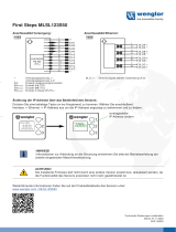
2.2.1 Analog sensor probe 2643A
Analog input with crank angle sensor probe (in-vehicle application):
For in-vehicle applications , you can directly connect a crank angle sensor
probe to KiBox2. This probe captures the crank angle position information
from the Engine Control Unit (ECU) and converts it into digital format com-
patible to KiBox2. The probe is powered by KiBox2 through same cable and
the analog-to-digital conversion is performed inside the electronic box. Please
see the schematic below for correct wiring.
NOTE
Green cable is not needed and has to be shielded or connected
to Ground (GND).
The crank angle probe 2643A can be connected directly to the engine crank
shaft position sensor and is replacing the 2619A crank angle adapter. Sup-
ported are hall and inductive sensors with every common crank angle geome-
try and an input range up to +/-50V (differential).
The probe is designed for rough engine environments with high vibration and
a high temperature range up to 120°C.
NOTE
Keep the sensor to probe connecting cable as short as possible
to improve the signal quality and reduces interferences by
electromagnetic fields and noise.

12/69 2895AK_002-984e-11.23
KiBox2 System, Type 2895AK
KiBox connection cable PIN assignment:
2.2.2 Digital I/O
Digital inputs are galvanic isolated between each other and the rest of the
system.
Digital outputs are TTL-level and have a common ground. They are not gal-
vanic isolated from each other, but the common ground is galvanic isolated
from the rest of the system.
Type: DSub 25 pol male
Name Function Pin
Digital I/O Digital In 1 + 1
Digital In 2 + 2
Digital In 3 + 3
Digital In 4 + 4
Digital In 5 + 5
Digital In 6 + 6
Digital In 7 + 7
Digital In 8 + 8
Digital Out common Ground 9
Digital Out 7 TTL + 10
Digital Out 5 TTL + 11
Digital Out 3 TTL + 12
Digital Out 1 TTL + 13
Digital In 1 - 14
Digital In 2 - 15
Digital In 3 - 16
Digital In 4 - 17
Digital In 5 - 18
Digital In 6 - 19
Digital In 7 - 20
Digital In 8 - 21
Digital Out 8 TTL + 22
Digital Out 6 TTL + 23
Digital Out 4 TTL + 24
Digital Out 2 TTL + 25
Type: Binder M8, series 718
4 polig female
99-3390-281-04

2895AK_002-984e-11.23 13/69
Commissioning
Properties Digital In
Maximum input level V ±30
Input level low V < 2
Input level high V > 4,5
Properties Digital Out
Maximum output level V 5.5
Output level low V < 2
Output level high V > 4
2.2.3 Sensor Connection
Maximum 16 data acquisition channels are supported. Each data acquisition
module supports one channel and can be freely inserted in the designated slots.
Available modules are:
– PEAQ Module Type 5075A : Amplifier for piezo-electric sensors
– PRAQ Module Type 4667A: Amplifier for piezo-resistive sensors
– VAQ Module Type 5270A/B: Universal highspeed voltage input
All sensor interfaces are galvanic isolated from the rest of the KiBox2 in order
to prevent potential differences lower to +/-75VDC are allowed. The isolation
barrier is functional and doesn’t fulfil any safety related isolation requirements.
2.3 Establishing connection
The communication between the KiBox2 and the KiBoxCockpit (Notebook)
will take place over a Gigabit Ethernet connection. This connection must be
configured accordingly. This is done by comparing the IP addresses between
KiBox2, and the notebook. If required, the IP address of KiBox2 can be
changed via the Kistler Network Setup Wizard.
Download and installation of this tool can be downloaded from the following link:
https://www.kistler.com/IT/en/p/powertrain-analysis-system-kibox2-
2895ak1/20000173
2.3.1 Ethernet settings and first connection
The KiBox2 system is delivered with the standard IP 192.168.0.100. In order
to be able to connect directly, the address of the Gigabit Ethernet card on
the notebook must be set to the value of 192.168.0.101. The subnet mask
of KiBox2 and the notebook must match. The default gateway of the KiBox2
must be set to the IP 192.168.0.254. Generally speaking, the KiBox and the
notebook must use the same network segment, but set to a different IP.
Example Configuration standalone operation and local vehicle network:
Notebook KiBox2
IP Address 192.168.0.101 192.168.0.100
Subnet Mask 255.255.255.0 255.255.255.0
Default Gateway no entry 192.168.0.254

14/69 2895AK_002-984e-11.23
KiBox2 System, Type 2895AK
Example configuration corporate network:
The notebook and the KiBox can be alternatively connected through a switch
to a corporate network. It should be noted, that in this case, the company-
specific network settings are standard.
NOTE
The company specific network settings may fundamentally
differ. A generally valid configuration can therefore not be
specified.
Please contact your network administrator for detailed settings
of the allowed IP range (IP address, subnet mask
How to set address of the Gigabit Ethernet card on the notebook:
1. Open Settings > Network Settings and click on "Change adapter options"
2. Choose the Ethernet interface connected to the KiBox and right-click to
select Properties. Choose IPv4 and click on Properties to change the
settings.

2895AK_002-984e-11.23 15/69
Commissioning
3. Assign the IP address such that the network segments of KiBox2 and
Notebook match.
2.3.2 Connection via WLAN
Before you can connect to the KiBox2 via WLAN, it is necessary to establish
an initial connection using Ethernet. This initial step allows you to set the
password and WLAN name for the device. Once you have completed this
setup process, you can then connect to the KIBox2 wirelessly.
1. Connect to the KiBox2 and open Wireless Access Point. There you can set
the name and network key for your device. Click on Change to update
device WLAN settings.

16/69 2895AK_002-984e-11.23
KiBox2 System, Type 2895AK
2. Ensure that your computer has Wi-Fi enabled. Locate the one device with the
SSID you set for your KiBox2. Select the Wi-Fi network and enter the password
you set earlier. Now you should be connected via WLAN yo the device.
3. By clicking on WLAN in the Cockpit, it will automatically connect to your
device, which is connected already with WLAN.

2895AK_002-984e-11.23 17/69
Commissioning
2.4 Cascading setup
Cascading set supports cascading of 2 to 4 units. The set consist of a PTP
capable ethernet switch, patch cable and power cable with 2x4mm-plugs. For
a proper switch configuration a predefinied .config file is provided.
Hardware Setup
Flexible in stacking horizontally or vertically.
Cockpit setting
Data merge of signals and results only happens in the KiBox Cockpit.
NOTE
Realtime performance only within same KiBox
• Calculators
• Monitors
• Digital I/O’s
• CAN Communication

18/69 2895AK_002-984e-11.23
KiBox2 System, Type 2895AK
2.5 Cockpit software
2.5.1 System Requirements
To ensure the reliable operation of the KiBox system, the following minimum
requirements of the PC must be met:
Processor 2 GHz (Dual Core)
RAM 4 GB
Hard disk space 1 GB (installed)
200 GB (data storage)
Ethernet 1 Gb
Operating system Windows 10, Windows 11
Please make sure your Windows user account has sufficient rights (such as
changing the firewall settings).
2.5.2 Cockpit Installation
Please install KiBox2 Cockpit on your PC running Windows10 by opening the
file KiBox2Installation.zip from the included USB Stick. Alternatively, the latest
version can be downloaded from the following link:
https://kibox-update.kistler.com/api/Deployment/downloadLatestVersion
To be automatically informed about newest releases an internet connecting is
necessary.
The installation wizard will lead you through the installation process by open-
ing the zip-file. After accepting the terms and conditions of the license agree-
ment the folder destination locations need to be selected on a Hard drive.
Windows is a registered trade mark of Microsoft Corporation

2895AK_002-984e-11.23 19/69
Commissioning
2.6 Home page
Start the application by double clicking on the KiBox. Cockpit.Shell.exe in
your chosen KiBox2 directory or Windows start menu.
Device status indication
No Designation Description
11Home/Back button To return to your configuration or to the home screen tap the Home/ Back button.
22Devices Add a KiBox via his IP-address or choose it directly from the network. When you first
launch the KiBox Cockpit the default IP settings are preconditioned. Tick the box to
cascade up to four devices (see Cascading). The Master KiBox with the reference
cylinder and crank angle source should be placed on the left-hand side. Right clicking
on a device shows the available options to restart, remove, switch off the device or
start auto start mode. This mode will automatically switch to measurement mode,
when powered up.
33Applications
Start a default template of your unlocked application package. Select both together
if you want to use it as an hybrid. In a dialog window you can choose if you want to
load the existing configuration from the KiBox. A dialog box allows you to choose
between loading an existing file from the KiBox or loading a default parameter file.
44Setups Open predefined configuration files (*.k2p).

20/69 2895AK_002-984e-11.23
KiBox2 System, Type 2895AK
55Measurements Measurement manager organizes your previous measurements as a database. The
data filter is based on ownership. The created captures/snapshots (*.MDF4) are
bundled in a Measurement file. Delete, share files or save complete measurements in
another path.
66Save log files If any major problem occurs, create a log file which will be saved automatically on the
desktop with the collected information.
77Global`s Notification: View information, errors and warnings. The system informs when a new
software release is available. Download the update first and execute it afterwards.
Configuration: This menu item opens a dialog box with four tabs. The register
“localization” changes the software language immediately, "units" includes settings
for unit selection for calculations and displays. The tab "Miscellaneous" includes
settings to active the audio feedback. Set the options for the remote control.
Help: opens the manual
88Device Information DHCP server dynamically assigns an IP address and other network configuration
parameters to each device on the network. Alternatively, the KiBox IP address can be
set individually and confirmed by the enter button.
Current state: Displays the current status of the KiBox2 device.
Status: Indicates the connection status of the device.
DHCP Server: Automatically assigns IP addresses and network configuration parame-
ters to connected devices.
Manual IP Address: Allows individual setting of the KiBox IP address with confirmation
by the enter button. Alternatively, the KiBox IP address can be set individually and
confirmed by the enter button.
Clock state: Shows synchronization status with other devices.
Storage: Indicates the allocated memory on the KiBox hard drive, with a maximum
capacity of 200 GB. Clean up disk by pressing the corresponding button.
99Licensing A connection to the internet is needed to activate / renew your acquired licenses.
Version A problem will occur if the firmware version is not matching your current software
version.
Wireless Access Point KiBox supports 2 wireless modes: Direct WLAN connection and acting as a hotspot.
PTP Synchronization Mainly used in cascaded mode: According to IEEE 1588: If necessary, the clock can be
synchronized with a third-party device clock that supports the Precision Time Protocol.
Primary is using the KiBox as the slave clock in the PTP environment. Secondary
switches the KiBox clock to master and from TAI to UTC timing.
2.6.1 Global`s detailed
77Notification Status: Status information about the KiBox
Message: Message of triggered monitors
Log: descripted Kibox logs
System update: connected to the internet the latest software version can be
downloaded and afterwards installed over the current installation.
77Configuration Localization: Change the language according to your preference. Please contact
kibox@kistler.com for any other wording recommendation.
Units: change the default units for the results
Miscellaneous: receive audio feedback on the Kibox actions
Active to load the configuration from the Kibox by default when connected.
Protect your configuration with a password.
Select your preferred signal domain: if connecting an input signal to a calculator on
calculator chain page and the input has domain 'Any', you have to choose if you want
to select AD or TD. This currently applies only to user calculators as other calculators
have ports with specific domain (either TD or AD).
77Help Opens the instruction manual document.
/