Dometic 579XX-590XX-595XX-59146 Series Roof Top AC_Use Installation guide
- Category
- Split-system air conditioners
- Type
- Installation guide

USA
SERVICE OFFICE
Dometic, LLC
2320 Industrial Parkway
Elkhart, IN 46516
574-294-2511
CANADA
Dometic, LLC
46 Zatonski, Unit 3
Brantford, Ontario
CANADA N3T 5L8
519-720-9578
For Service Center
Assistance Call:
800-544-4881
MODELS
Important: These instructions must
stay with unit. Owner read carefully.
REVISION
Form No. 3108464.102 8/09
Replaces 3108464.094)
(French 3108982.103)
©2009 Dometic, LLC
LaGrange, IN 46761
This manual must be read and
understood before installation,
adjustment, service, or mainte-
nance is performed. This unit must
be installed by a qualied service
technician. Modification of this
product can be extremely hazard-
ous and could result in personal
injury or property damage.
Lire et comprendre ce manuel avant
de procéder à l'installation, à des
réglages, de l'entretien ou des répa-
rations. L'installation de cet appareil
doit être effectuée par un réparateur
qualié. Toute modication de cet
appareil peut être extrêmement dan-
gereuse et entraîner des blessures ou
dommages matériels.
RECORD THIS UNIT INFORMATION
FOR FUTURE REFERENCE:
Model Number
Serial Number
ADB Model Number
ADB Serial Number
Date Purchased
INSTALLATION INSTRUCTIONS
This unit is designed for OEM installation.
Roof Top Unit
Description Model Use With Air Distribution Box
Model Analog Control Kit
Air Conditioner 579XX 3107210.XXX 3107541.XXX
590XX
595XX
Heat Pump 59146 3107210.XXX 3107546.008
57908.321
57908.521
57912.531
57912.532
57912.622
57912.631
57915.322
57915.331
57915.336
57915.341
57915.346
57915.422
57915.522
57915.531
57915.536
57915.541
57915.546
57915.622
57915.631
57915.731
57915.741
57915.746
59016.521
59016.621
59146.751
59516.303
59516.331
59516.336
59516.501
59516.531
59516.536
59516.601
59516.603
59516.631
59516.731
3108464.102

2
SAFETY INSTRUCTIONS
This manual has safety information and instruc-
tions to help users eliminate or reduce the risk
of accidents and injuries.
RECOGNIZE SAFETY INFORMATION
This is the safety-alert symbol. When you see this
symbol in this manual, be alert to the potential
for personal injury.
Follow recommended precautions and safe op-
erating instructions.
UNDERSTAND SIGNAL WORDS
A signal word, WARNING OR CAUTION is used
with the safety-alert symbol. They give the level
of risk for potential injury.
indicates a potentially hazard-
ous situation which, if not avoided, could result
in death or serious injury.
indicates a potentially hazard-
ous situation which, if not avoided, may result in
minor or moderate injury.
used without the safety alert
symbol indicates, a potentially hazardous situa-
tion which, if not avoided, may result in property
damage.
Read and follow all safety information and in-
structions.
GENERAL INFORMATION
1. Product features or specications as described or il-
lustrated are subject to change without notice.
2. This air conditioner/heat pump (hereinafter referred to
as the "unit") is designed for:
1. Installation on a recreational vehicle during the
time the vehicle is manufactured.
2. Mounting on the roof of a recreational vehicle.
3. Roof construction with rafters/joists on minimum
of 16 inch centers.
4. Minimum of 2 inch and maximum of 4 inches dis-
tance between roof to ceiling of recreational ve-
hicle.
3. The ability of the air conditioner to maintain the de-
sired inside temperature depends on the heat gain of
the RV.
Some preventative measures taken by the occupants
of the RV can reduce the heat gain and improve the
performance of the air conditioner. During extremely
high outdoor temperatures, the heat gain of the ve-
hicle may be reduced by:
1. Parking the RV in a shaded area
2. Using window shades (blinds and/or curtains)
3. Keeping windows and doors shut or minimizing
usage
4. Avoiding the use of heat producing appliances
Operation on High Fan/Cooling mode will give opti-
mum or maximum efciency in high humidity or high
outside temperature.
Starting the air conditioner early in the morning and giving
it a "head start" on the expected high outdoor ambient will
greatly improve its ability to maintain the desired indoor
temperature.
For a more permanent solution to a high heat gain, ac-
cessories like A&E outdoor patio and window awnings will
reduce heat gain by removing the direct exposure to the
sun. They also add a nice area to enjoy company during
the cool of the evening.
4. Condensation
Note: The manufacturer of this unit will not be responsible
for damage caused by condensed moisture on ceilings or
other surfaces. Air contains moisture and this moisture
tends to condense on cold surfaces. When air enters the
RV, condensed moisture may appear on the ceiling, win-
dows, metal parts, etc. During normal operation this unit
removes moisture from the air. Keeping doors and win-
dows closed when this air conditioner is in operation will
minimize condensed moisture on cold surfaces.

3
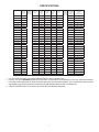
Model No. Nominal
Capacity
(BTU HR)
Cooling
Electrical
Rating
120 VAC
60Hz. 1PH
Compressor
Rated Load
Amps
Compressor
Locked
Rotor
Amps
Fan Motor
Rated Load
Amps
Fan Motor
Locked
Rotor
Amps
Refrigerant
R-22
(Oz.)
Minimum
Wire Size*
12 AWG
Copper
Up to 24'
AC Circuit
Protection
***Installer
Supplied
Minimum
Generator
Size**
1 Unit / 2 Units
57908.321 7,180 6.9 36.0 2.5 5.8 16.0 20 Amp 2.5 KW / 4.0 KW
57908.521 7,100 6.6 34.0 2.5 5.8 17.0 20 Amp 2.5 KW / 4.0 KW
57912.531 11,000 8.0 53.0 2.5 5.8 18.5 20 Amp 2.5 KW / 4.0 KW
57912.532 11,000 12.1 59.0 2.5 5.8 16.5 20 Amp 2.5 KW / 4.0 KW
57912.622 11,000 8.5 48.3 2.5 5.8 18.0 20 Amp 2.5 KW / 4.0 KW
57912.631 11,000 8.5 48.3 2.5 5.8 18.0 20 Amp 2.5 KW / 4.0 KW
57915.322 13,500 11.4 58.0 2.5 5.8 15.5 20 Amp 3.5 KW / 5.0 KW
57915.33X 13,500 11.4 58.0 2.5 5.8 15.5 20 Amp 3.5 KW / 5.0 KW
57915.34X 13,500 11.5 58.0 2.5 5.8 15.5 20 Amp 3.5 KW / 5.0 KW
57915.422 13,500 11.5 50.0 2.5 5.8 14.5 20 Amp 3.5 KW / 5.0 KW
57915.522 13,500 12.1 59.0 2.5 5.8 16.5 20 Amp 3.5 KW / 5.0 KW
57915.53X 13,500 12.1 59.0 2.5 5.8 16.5 20 Amp 3.5 KW / 5.0 KW
57915.54X 13,500 11.3 62.0 2.5 5.8 16.0 20 Amp 3.5 KW / 5.0 KW
57915.622 13,500 11.0 54.4 2.5 5.8 16.5 20 Amp 3.5 KW / 5.0 KW
57915.631 13,500 11.0 54.4 2.5 5.8 16.5 20 Amp 3.5 KW / 5.0 KW
57915.731 13,500 11.3 56.0 2.5 5.8 15.0 20 Amp 3.5 KW / 5.0 KW
57915.74X 13,500 12.2 58.0 2.5 5.8 15.5 20 Amp 3.5 KW / 5.0 KW
59016.521 15,000 12.9 71.0 2.5 6.0 26.5 20 Amp 3.5 KW / 5.0 KW
59016.621 15,000 12.9 77.0 2.5 6.0 26.5 20 Amp 3.5 KW / 5.0 KW
59146.751 15,000 13.3 62.0 2.5 6.0 30.3 20 Amp 3.5 KW / 5.0 KW
59516.303 15,000 12.7 60.0 2.0 5.6 29.0 20 Amp 3.5 KW / 5.0 KW
59516.33X 15,000 12.7 60.0 2.0 5.6 29.0 20 Amp 3.5 KW / 5.0 KW
59516.501 15,000 12.7 79.0 2.5 5.8 31.0 20 Amp 3.5 KW / 5.0 KW
59516.53X 15,000 12.7 79.0 2.0 5.6 29.0 20 Amp 3.5 KW / 5.0 KW
59516.601 15,000 12.9 77.0 2.5 6.0 31.0 20 Amp 3.5 KW / 5.0 KW
59516.603 15,000 12.3 77.0 2.0 5.6 29.5 20 Amp 3.5 KW / 5.0 KW
59516.631 15,000 12.3 71.0 2.0 5.6 29.5 20 Amp 3.5 KW / 5.0 KW
59516.731 15,000 13.3 62.0 2.0 5.6 29.0 20 Amp 3.5 KW / 5.0 KW
SPECIFICATIONS
* For wire length over 24 ft., consult the National Electric Code for proper sizing.
** Dometic, LLC gives GENERAL guidelines for generator requirements. These guidelines come from experiences people
have had in actual applications. When sizing the generator, the total power usage of your recreational vehicle must be
considered. Keep in mind generators lose power at high altitudes and from lack of maintenance.
*** CIRCUIT PROTECTION: Time Delay Fuse or HACR Circuit Breakers Required.

4
2. The roof must be designed to support 130
pounds when the RV is in motion. Normally a
200 lb. static load design will meet this require-
ment.
3. Check inside the RV for air distribution box
obstructions (i.e. door openings, room dividers,
curtains, ceiling xtures, etc.). See FIG. 4.
C. After Location Has Been Selected:
1. Check for obstructions in the area where unit
will be installed. See FIG. 3
1. Precautions
Improper installation may damage equipment
could endanger life, cause serious injury and/
or property damage.
A. Read Installation and Operating Instructions care-
fully before attempting to start this unit installa-
tion.
B. Dometic, LLC will not be liable for any damages
or injury incurred due to failure in following these
instructions.
C. Installation must comply with the National Electri-
cal Code ANSI/NFPA-70 and CSA Standard C22.1
(latest edition) and any State or Local Codes or
regulations.
D. DO NOT add any devices or accessories to this
unit except those specically authorized in writing
by Dometic, LLC.
E. This equipment must be serviced by qualied
personnel and some states require these people
to be licensed.
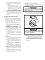
2. Choosing Proper Location For Unit
This unit is specically designed for installation on the
roof of a recreational vehicle (RV).
A. Normal Location
The unit is designed to t over an existing roof vent
opening. When the vent is removed, it normally
creates a 14-1/4" X 14-1/4" (±1/8") opening. See
FIG. 1.
INSTALLATION INSTRUCTIONS
It is preferred that the unit be installed in a relatively
at and level roof section measured with the RV
parked on a level surface, but up to a 15° tilt is
acceptable.
FIG. 1
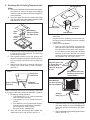
B. Other Locations
When no roof vent is available or another location
is desired, the following is recommended:
1. For one unit installation: The unit should be
mounted slightly forward of center (front to
back) and centered from side to side.
2. For two unit installations: Install one unit1/3 and
one unit 2/3’s from front of RV and centered
from side to side. See FIG. 2.
1/2L LL
1/3L
2/3L
FIG. 2
It is the responsibility of the installer of this
unit system to ensure structural integrity of
the RV roof. Never create a low spot on the
roof where water will collect. Water standing
around the unit may leak into the interior
causing damage to the product and the RV.
FIG. 3
Dimensions Are Nominal
Dimensions Are Nominal
13-1/8"
34-7/8" 29-7/8"
14-1/4" x 14-1/4"
(± 1/8") Opening
Keep This Area Free Of Obstructions
18"
Front
Center Line
Of Unit

5
3. Roof Preparation
Before preparing the ceiling opening, the type of system
options must be decided upon. If a furnace is to be con-
nected, wires must be run from the furnace to the Dometic
A/C. Read all of the following instructions before beginning
the installation.
There may be electrical wiring between the
roof and the ceiling. Disconnect 120 VAC
power cord and the positive (+) 12 VDC ter-
minal at the supply battery. Failure to follow
this instruction may create a shock hazard
causing death or severe personal injury.
A. Ceiling Opening Requirements
1. A 14-1/4" x 14-1/4" (±1/8") opening must be
cut through the roof and ceiling of the RV. This
opening must be located between the roof
reinforcing members.
2. Mark a 14-1/4" x 14-1/4" (±1/8") square on the
roof and carefully cut the opening.
3. Using the roof opening as a guide, cut the
matching hole in the ceiling.
B. Opening Preparation
1. If the opening exceeds 14-3/8" x 14-3/8", it will
be necessary to install spacers.
2. If the opening is less than 14-1/8" x 14-1/8", it
must be enlarged.
3. Route a copper 12 AWG, with ground, 120 VAC
supply line from the fuse or circuit breaker box
to the roof opening.
a. This supply line must be located in the
front portion of the 14-1/4" x 14-1/4" (±1/8")
opening.
b. The power MUST be on a separate time
delay fuse or HACR circuit breaker. The
proper size protection can be determined
from the chart on page 3.
c. Make sure that at least 15" of supply wire
extends into the roof opening. This ensures
easy connection at the junction box.
d. Wiring must comply with NFPA 70: National
Electrical Code regulations and any State
or Local Codes or regulations.
e. Protect the wire where it passes into the
opening with approved method. See para-
graph "d" above.
4. If a furnace is to be connected, wires must be
run from the furnace to the roof opening.
5. The opening created must be framed to provide
adequate support and prevent air from being
drawn from the roof cavity. Framing stock 3/4"
or more in thickness must be used. Remember
to provide an entrance hole for power supplies,
furnace wiring (if applicable) and thermostat
wires. See FIG. 5.
It is the responsibility of the installer of this
unit system to ensure structural integrity of
the RV roof. Never create a low spot on the
roof where water will collect. Water standing
around the unit may leak into the interior
causing damage to the product and the RV.
6. The 14-1/4" x 14-1/4" (±1/8") opening is part
of the return air system of the unit and must
be nished in accordance with NFPA Standard
501C Section 2.7.
FIG. 5
Do Not Cut
Roof Structure
Or Rafters
Good-Rafters
Supported By
Cross Beams
Good Location-
Between Roof
Rafters
Frame Opening So It
Won't Collapse When
Bolting Down Unit
Leave Access For Power
Supply Wiring
15" Min. At
Front Of
Opening
3/4" Min.
FIG. 4
20"
22-1/2"
2-1/2"
Dimensions Are Nominal
Dimensions Are Nominal
11-1/4"11-1/4"
3"
2-3/4"
20"
14-1/4" x 14-1/4"
(± 1/8") Opening

6
7. Route a dedicated 12 VDC supply line (18-22
AWG) from the RV's converter or battery to the
roof opening.
a. Wire must be fused at 3 Amps.
b. This supply line must be located in the front
portion of the 14-1/4" (±1/8") opening.
c. Make sure that at least 15" of supply wire
extends into the roof opening.
8. If a furnace is to be controlled by the system,
the two furnace thermostat leads must be
routed to the roof opening of the unit that will
control it. Make sure that at least 15" of the
furnace thermostat wire extend into the roof
opening.
4. Thermostat And Cable Installation
A. Location
The proper location of the thermostat is very im-
portant to insure that it will provide a comfortable
RV temperature. Observe the following general
rules when selecting a location.
1. Locate the thermostat about 54" above the
oor.
2. Install thermostat on a partition, NEVER on an
outside wall;
3. NEVER expose it to direct heat from lamps,
sun or other heat producing items;
4. Avoid locations close to doors that lead outside,
windows or adjoining outside walls;
5. Avoid locations close to supply registers and
the air from them;
6. Never locate thermostat in a room that is warmer
or cooler than the rest of the coach - such as
the kitchen.
7. The major living area is normally a good loca-
tion.
B. Cable Installation
1. A seven-conductor cable, 18 to 22 AWG is to
be used for low voltage connections.
2. Choose the shortest, direct route from the 14-
1/4" (± 1/8") opening to the thermostat location
selected.
3. Consider where screws, nails or staples might
contact the cable.
4. Leave approximately 6" of cable extending
through the wall for connection to the thermo-
stat.
5. Leave approximately 10" of cable extending
into the 14-1/4" ± (1/8") opening for connection
at unit
6. If system is to control a gas furnace: Route two
18 gauge wires from the furnace to the 14-1/4
x 14-1/4" (± 1/8") opening.
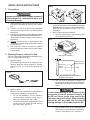
5. Placing The Unit On The Roof
A. Remove the unit from the carton and discard.
B. Place the unit on the roof.
This unit weighs approximately 100 pounds.
To prevent back injury, use a mechanical hoist
to place unit on roof.
C. Lift and place the unit over the prepared opening
using the gasket on unit as a guide. See FIG. 6.
FIG. 6
D. Place the air distribution box kit and analog control
kit inside the RV. Both boxes contain mounting
hardware for the unit and will be used inside the
RV. This completes the outside work. Minor ad-
justments can be done from the inside of the RV
if required.
Do not slide the unit. This may damage the
neoprene gasket attached to the bottom and
create a leaky installation.
Front

7
FIG. 8
Center Unit
From Below
Pull Down
Electrical Cord
Measure Ceiling
Thickness
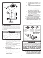
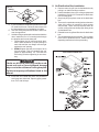
6. Discharge Duct & Ceiling Template Instal-
lation
A. Remove the air distribution box and mounting hard-
ware from their carton. The upper duct is shipped
inside the lower duct which is inserted through the
ceiling template.
B. Place the upper duct over the blower discharge
with the edges without the anges toward the rear
and side of the opening. See FIG. 7.
C. Install two of the sharp pointed sheet metal screws
to hold the duct to the base pan. The holes are
pre-punched in the pan.
D. Check gasket alignment over roof opening and
adjust if necessary (roof gasket centers over open-
ing). Unit may be moved from below by lifting and
sliding.
E. Reach up into the return air opening and pull the
conduit power cable down for later connection.
See FIG. 8.
Note: In some applications it may be necessary to extend the
6 pin cable. Order cable number 3105584.001 if needed.
F. Measure the ceiling thickness:
1. If the distance is 2" to 3", remove perforated
tabs from bottom duct only.
2. If the distance is 3" to 4", install ducts as re-
ceived.
3. If the distance is 4" to 6" (maximum thickness),
optional Duct Kit and Bolt Kit are available:
Duct Kit (Part No. 3106775.004)
Bolt Kit (Part No. 3100895.006)
G. Place the lower duct through the template and
install with (2) #10 x 3/8" screws. See FIG. 9.
H. Remove the junction box cover from the analog
control box.
I. Plug the electrical conduit (6 pin connector) from
the upper unit into the mating connector in Analog
Control Box.
J. Freeze Control Installation
1. Place the cold control switch up through the
base pan and on the second refrigerant tube
from the bottom in the center of the evapora-
tor coil. Make sure the spring clip is fastened
securely to the tubing and the cold control
surface is making contact with aluminum ns
on evaporator coil. See FIGS. 10 &11.
FIG. 10
Wrap Closed Cell Foam
Insulation Around Cold
Control Switch
Snap The Open Loop
Of Spring Clip On
Second Tube In
Center OF Evapora-
tor Coil
2. Keep wires away from heat strip (if applicable)
and sharp edges to prevent damaging the
wires. Use wire ties if necessary. See FIGS.
10 & 11.
3. Remove installation notice hang tag from freeze
control. See FIG. 11.
FIG. 7
Side Without
Tabs Are To Rear
And Side Of Unit
Screw
Lower
Duct
Screw
Upper
Duct
Remove
Hang Tag
Up
Through
Install Between
Fins Over Second
Tube From Bottom
FIG. 11
Duct Screws
Mounting Bolts
Mounting Bolts
Discharge
Air Duct
FIG. 9

8
THERMOSTAT WITH COVER REMOVED
FIG. 12
Disconnect the positive (+) 12 VDC terminal
at the supply battery. Damage to equipment
could occur if the 12 VDC is not shut off.
7. Wiring The System
A. 120 VAC Power Supply Connection
1. Route the 120 VAC supply line through the
strain relief in analog control box.
2. Connect the white to white; black to black;
and green to green or bare copper wire using
"listed" wire connectors.
3. Tighten strain relief, making sure enough wire
Disconnect 120 VAC. Failure to follow these
instructions could create a shock hazard
causing death or severe personal injury.
This product is equipped with a 3-wire
(grounded) system for protection against
shock hazard. Make sure that the unit is wired
into a properly grounded 120 VAC circuit and
the polarity is correct. Failure to do so could
result in death, personal injury or damage to
the equipment.
is inside electronic box to connect with unit
120 VAC wire. Tighten screws on strain relief
connector. Be careful not to damage wires.
3. Push the wires into the box.
4. Install the cover (part of the mounting hardware)
with the one blunt point screw provided.
B. Low Voltage Wire Connection
1. Current model color coding
a. Connect the previously run positive +12V
DC to the red wire labeled +12V from the
analog control box.
b. Connect the previously run negative -12V
DC to the black wire labeled -12V from the
analog control box.
c. Connect the green wire from the analog
control box to the thermostat GND termi-
nal.
d. Connect the red/white wire from the analog
control box to the thermostat +7.5 termi-
nal.
e. Connect the yellow wire from the analog
control box to the thermostat COOL termi-
nal.
f. Connect the tan wire from the analog control
box to the thermostat FAN terminal.
g. Connect the blue wire from the analog
control box to the thermostat HI FAN ter-
minal.
h. Connect the orange wire from the analog
control box to the thermostat HS or HP
terminal (if applicable).
i. Connect the white wire from the analog
control box to the thermostat FUR terminal
(if applicable).
j. Connect the blue/white wires from the ana-
log control box to the two furnace control
wires (if applicable).
2. Early model color coding
a. Connect the previously run +12 VDC to
the red wire labeled +12V from the analog
control box. Connect the previously run
-12V DC to the black wire from the analog
control box.
b. Connect the other red wire labeled +12V
to thermostat +12 terminal.
c. Connect the other analog control box black
wire (unmarked) to the thermostat GND
terminal.
d. Connect the analog control box yellow wire
to the thermostat COOL terminal.
e. Connect the analog control box orange
wire to the thermostat FAN terminal.
f. Connect the analog control box blue wire
to the thermostat HI FAN.
g. Connect the analog control box violet wire
to the thermostat HS/HP terminal (if ap-
plicable).
h. Connect the analog control box white wire
to the thermostat furnace terminal (if ap-
plicable).
i. Connect the analog control box blue wires
with white stripe to the two furnace control
wires (if applicable).
C. Install the analog control box on the ceiling template
as shown in FIG. 13. Drive two #10 x 3/8" blunt
point Phillips head screws (provided) through ceil-
ing template into holes in the analog control box
to hold into place.

9
D. If your installation includes the optional electric heat
kit, install it at this time. Follow the instructions with
the heat package for its installation procedure.
E. Take the ceiling template and slide the lower unit
over the upper duct.
F. Hold the ceiling template with one hand and with the
other, install the four 1/4" mounting bolts through
the template and into the base pan.
1. Finger-tighten the (4) bolts and check align-
ment. There should be an equal opening on
each side and the rear ange must be tight
against the roof opening.
2. EVENLY tighten the bolts to a torque of 40 to
50 inch pounds. This will compress the roof
gasket to approximately 1/2". The bolts are
self locking so further tightening is not neces-
sary.
G. Insure the duct "Break Off Tabs" are positioned
so air gaps are minimized. Tape any gaps greater
than 1/16" with foil tape.
FIG. 13
If bolts are left loose there may not be an ad-
equate roof seal or if over tightened, damage
may occur to the unit base or ceiling template.
Tighten to torque specications listed in this
manual.
AIR CONDITIONING UNIT
FIG. 14
Analog
Control Box Ceiling
Template
8. Air Distribution Box Installation
A. Remove return air grill from air distribution box by
pulling in on half round nger catches.
B. Hold air distribution box up to ceiling template and
install three (3) #10 x 3/8" screws at air distribution
box mounting point.
C. Snap hole plug into place at rear of air distribution
box.
D. There are four optional mounting holes on the outer
edge of the return air opening for which screws
are provided. These are only required where an
uneven ceiling does not allow proper tting of the
air distribution box.
E. Reinstall return air grill and lter into air distribution
box.
F. The unit installation is now complete. Turn on power
to the unit for operational check. Please read Unit
Operating Instructions before proceeding.

10
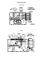
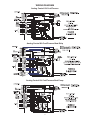
WIRING DIAGRAM
579, 590 & 595
59146

11
Analog Control Kit Cool/Furnace
WIRING DIAGRAM
Analog Control Kit Cool/Furnace/Heat Strip
Analog Control Kit Cool/Furnace/Heat Pump
-
 1
1
-
 2
2
-
 3
3
-
 4
4
-
 5
5
-
 6
6
-
 7
7
-
 8
8
-
 9
9
-
 10
10
-
 11
11


Dometic 579XX-590XX-595XX-59146 Series Roof Top AC_Use Installation guide
- Category
- Split-system air conditioners
- Type
- Installation guide
Ask a question and I''ll find the answer in the document
Finding information in a document is now easier with AI
Related papers
-
Dometic 590 Series User manual
-
-
Dometic 600315.326 Installation Instructions Manual
-
-
-
-
-
Dometic Roof Top Unit Used Operating instructions
-
-