Page is loading ...

700-3003-BC 4.29.2021
POOL LIFT –
CEC COMPLIANT MODELS
ROUND POST MODELS
FOR USE WITH Ø 2.38” X 6” DEEP ANCHORS
OWNER’S MANUAL
&
MAINTENANCE PROCEDURES
S.R. SMITH, LLC
CORPORATE HEADQUARTERS
P.O. Box 400 • 1017 S.W. Berg Parkway
Canby, Oregon 97013 USA
Phone (800) 824 4387 • Fax (503) 266 4334
www.srsmith.com

2
DECK PROFILE SHEET CONFIRMATION
Aquatic access lifts are application specific. A completed Deck Profile Sheet helps to ensure the lift
purchased for the application will work in accordance to ADA guidelines. S.R. Smith reviews all submitted
Deck Profile Sheets as a service to our customers, free of charge. Before installing the pool lift, the
installer must review and confirm the information provided on the Deck Profile Sheet. If the description of
the application does not match the installation site, a new Deck Profile Sheet must be completed and
submitted to S.R. Smith.
NOTE: FAILURE TO COMPLETE AN ACCURATE DECK PROFILE SHEET MAY RESULT IN THE
LIFT NOT MEETING ADA COMPLIANCE GUIDELINES.
To complete the Deck Profile Sheet online, visit www.srsmith.com/liftprofile, contact Customer Service at
(800) 824-4387 or email sales@srsmith.com.

3
TABLE OF CONTENTS
aXs2 ROUND POST MODEL (P/N: 310-0000R)
DECK PROFILE SHEET CONFIRMATION .................................................................................................. 2
INTRODUCTION ........................................................................................................................................... 4
WARNINGS AND SAFETY SUMMARY ....................................................................................................... 5
PRODUCT OVERVIEW ................................................................................................................................ 6
aXs2 - PRODUCT COMPONENTS .............................................................................................................. 6
UNPACKING & ASSEMBLY INSTRUCTIONS ........................................................................................... 11
USING THE aXs2 LIFT ............................................................................................................................... 16
TRANSFERRING ........................................................................................................................................ 17
STANDARD ACCESSORIES/OPTIONAL ACCESSORIES ....................................................................... 19
MAINTENANCE and CLEANING ............................................................................................................... 20
TROUBLE SHOOTING ............................................................................................................................... 21
LONG-TERM STORAGE ............................................................................................................................ 22
PRODUCT REGISTRATION & WARRANTY INFORMATION ................................................................... 22
SPECIFICATIONS ...................................................................................................................................... 23
1. Dimensions/Capacity ........................................................................................................................... 23
2. Actuator ............................................................................................................................................... 23
3. Motor.................................................................................................................................................... 23
4. Battery ................................................................................................................................................. 23
5. Range of Motion Information ............................................................................................................... 23
6. Noise.................................................................................................................................................... 23
7. Materials and Finish Information ......................................................................................................... 23
PARTS LIST ................................................................................................................................................ 24

4
READ THESE INSTRUCTIONS IN THEIR ENTIRETY BEFORE
BEGINNING INSTALLATION
INTRODUCTION
The purpose of this document is to provide information relating to the safe operation, care, and
maintenance of the aXs2.
Intended Lift User:
All of S.R. Smith’s lifts have been designed to assist anyone who has problems entering or exiting a
swimming pool or spa - the only restriction is that the User does not exceed the weight limit of the product
(300 lb/136 kg). It is the responsibility of the lift Owner to ensure that the correct safety procedures have
been put in place and a risk assessment carried out. If a User is mentally challenged or has severe
physical disabilities these issues must be taken into account to determine the number of persons required
to complete the transfer onto the seat and the number of persons required to be in the water, ready to
receive the User. The correct seat belt must be attached to the seat and fully fastened and used during
each transfer.
Our goal is to provide our customers with the most advanced and innovative designs offering exceptional
quality at affordable prices. All of our lifts meet the specifications set forth by the Access Board - ADAAG
2004 (US only), Medical Device Directive, 93/42/EEC, RoHS2 Directive 2011/65/EU, EN 50581:2012
and ISO10535:2006 including repeating the lifting cycle of the hoist (lift) over a total of 11,000 cycles. The
lift system and AC powered battery charger complies with EN60601-1-2, 2007/03.
US Patent No. 5,790,995
aXs2, and LiftOperator are registered trademarks of S.R. Smith, LLC.
Model / Product No.______
Product Name ___________
S.R. Smith, LLC
PO Box 400
1017 SW Berg Parkway
Canby, Oregon 97013 USA
Phone: 503-266-2231
Fax: 503-266-4334
www.srsmith.com
Assembled in USA
SN S
24 VDC

5
WARNINGS AND SAFETY SUMMARY
DANGER – FAILURE TO FOLLOW THESE WARNINGS, INSTRUCTIONS AND THE OWNER’S MANUAL
MAY RESULT IN SEROUS INJURY OR DEATH
ADA GUIDELINE SUMMARY* (USA Only)
1009.2.1 Pool Lift Location
Pool lift shall be located where the water level does not exceed 48”. If entire pool water level exceeds
48”, place pool lift where convenient.
1009.2.2 Seat Location
In the raised position, the centerline of the seat shall be located over the deck a minimum of 16” from the
edge of the pool.
1009.2.3 Clear Deck Space
On the side of the seat opposite the water; a clear deck space shall be provided parallel with the seat.
The space shall be 36” wide minimum and shall extend forward 48” minimum from a line located 12”
behind the rear edge of the seat.
1009.2.4 Seat Height
The lift shall stop at 16” – 19” measured from the deck to the top of the seat surface when in the loading
position.
1009.2.8 Submerged Depth
The lift shall submerge the seat a minimum of 18” below the stationary water level.
*Compliance with ADA is the responsibility of the pool owner. Visit www.ada.gov for complete guidelines.

6
PRODUCT OVERVIEW
The aXs2 Aquatic Lift is a fixed lift system designed so that individuals with disabilities and mobility
impairments can have universal access to residential, commercial and community swimming pools or spas.
The aXs2 is powered by a 24 Volt DC rechargeable battery. The lifting motion is provided by a screw driven
electronic actuator and an electronic gear motor provides the turning motion. S.R.Smith has endeavored to
design the safest possible lift system, however, lift users are responsible to follow all instructions in the
owner’s manual, and all product labels to help ensure safe, reliable and proper performance of the lift to
avoid injury. The aXs2 has a mast height of 46”/117 cm above the deck, provides 360º rotation and is
intended to be used with simple pool gutter configurations having a deck to water distance of no more than
eight inches. The maximum lift capacity for aXs2 is 300 lb/136 kg. Only persons healthy enough for water
activities should use the aXs2. Users should consult with their physician to determine if water activities are
appropriate for the User.
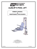
aXs2 - PRODUCT COMPONENTS
aXs2 310-0000R
SEAT ARM
ACTUATOR
BATTERY
MAST
SUPPORT ARM
SEAT
ACTUATOR ARM
4-Button
HAND CONTROL
CONTROL BOX
MOTOR
ASSEMBLY
MOTOR
ENCLOSURE
BASE INSERT STEM
FOOTREST

7
COMPONENT DESCRIPTION
The lift is made up of several components:
Base Assembly - Mounts to the pool deck and contains the turning elements of the lift.
Base Insert Stem - Slides into an anchor sleeve that is installed on the pool deck.
Mast - The main vertical component of the lift.
Actuator Arm - Primary lifting arm of the lift connects the mast to the seat arm and is raised by the
attached actuator.
Support Arm - Provides stability for the seat frame.
Seat Arm - Provides an attachment point for the seat assembly to the actuator and support arms.
Motor Enclosure (left & right) - ABS plastic cover shields base assembly components from weather.
When cleaning the enclosure, be sure to use a clean, soft, non-abrasive material.
Actuator - Provides the up and down lifting action.
Motor Assembly – Consists of a 24-volt motor and gearing.
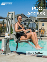
Control Box - The LiftOperator unit controls all lift operations with touchpad buttons on the front panel
that are identical to the user hand set. Three cables connect to the bottom of the Control Box to enable
operation of the lift. The largest connector is for the hand control. Connector # 1 is for the motor cable
(red stripe). Connector # 2 is for the actuator cable (green stripe).
Touchpad Control –
The touchpad control arrow keys can be used in the event that
the hand control is out of reach or fails. Simply press and hold
the arrow for the desired action for one movement at a time –
Up, Down, Left, Right. Releasing the Arrow stops movement.
Battery Level LED Indicators –
The Battery Level LED Indicators show battery charge levels.
The LED’s will illuminate when either the touchpad control or the
hand control is activated and will stay lit for 10 seconds. At
greater than 50% the LED glows Green, at less than 50% the
LED glows Amber, and less than 25% the LED glows red and
indicates the battery requires charging. If the battery level is
less than 25%, do not operate the lift. Remove the battery and
fully charge before use.
Emergency Stop Button –
In the event of an emergency, or if you need to stop lift movement immediately, pressing the
Emergency Stop Button (red button on the control) will stop all lift movement. At the same time an
audible alert will sound for 10 sec. then pause for 5 sec. and then the sequence will repeat until
the button is reset by turning it in the direction of the arrows on the button (clockwise). The
Emergency Alert LED will also flash Red when the button is pressed and will remain flashing until
the button is reset.
The Emergency Alert (audible and LED) can be activated by pressing any two buttons on the
hand control at the same time (provided with the lift). This will stop all lift movement and activate
CONNECTOR 2
(ACTUATOR CABLE)
CONNECTOR 1
(MOTOR CABLE)

8
the audible alert and the Red LED will flash. Once both buttons are released, the lift will return to
normal operation and the emergency audible alert will silence.
For additional information on the LiftOperator controller, see LiftOperator manual 700-0500.
Battery Pack - The battery pack is located on top of the Control Box and is removable.
To remove - pull the battery pack away from the mounting plate so that the latch on the battery
pack clears the side tabs on the mounting plate - then lift the battery pack up and away from the
Control Box.
To replace - align the battery pack with the mounting plate so that the latch will drop over the
center tab and that the bottom of the battery pack will fit in the recessed area on top of the Control
Box. Lower the battery pack in place so that the latch is fully captured by the mounting plate and
the battery pack drops fully seated onto the Control Box.
The battery must be completely removed from the lift and located away from the pool deck for
charging.

9
*Image courtesy of Deltran Battery Tender
The battery pack should be charged daily. Do not allow battery to fully discharge, as it will shorten battery
life. Whenever battery is removed from Control Box or lift that is not in use it is important to connect the
battery to the charger. This ensures battery is fully charged and ready for use.
Prior to connecting the charger to the battery, make sure that the LEAD ACID battery type is
selected and that the selected voltage is 24V. After the correct battery type and voltage is
selected, connect the charger to the battery.
The battery charger has an LED indicator to show charging status. The following describes LED indicator
operation.
Amber Light Flashing – The amber light flashing indicates that the battery charger has AC power and
the microprocessor is functioning properly. If the amber light continues to flash, either the battery voltage
is too low (battery pack needs to be replaced), or the battery charger is not properly connected to the
battery.
Alternating Green/Amber (Amber LED & Green)
• This indicates reverse polarity connection to the battery.
or
• The charger’s safety timer has activated due to the battery not reaching its optimal voltage. The
battery may be defective, contact S.R. Smith customer service for troubleshooting.
Amber Light on Steady – Whenever the amber light is on steady, a battery is connected properly to the
charger and the charger is charging the battery. The amber light will remain on until the charger
completes the charging stage.
Green Light Flashing – When the charger shows a green flashing light, the battery is 80% charged.
Whenever possible, leave the battery on the charger until the green light is solid.
Green Light on Steady - When the green light stops flashing and remains on steady, the battery is fully
charged and can be returned to service. The battery can and should be left on the charger when not in
use.
Batteries have a normal lifespan of between 2-3 years, depending on use and care. A fully charged
battery will provide approximately 30 to 40-lifting cycles, depending on the weight of the users. Prior to
use the battery charge level should be checked by observing the LED indicator on the charger plug to
ensure sufficient charge level. See warranty policy regarding battery replacement.

10
It is not necessary to fully discharge the battery prior to charging. Battery should be charged daily and
cannot be overcharged. It takes up to twelve hours to fully charge depending upon battery usage. Do not
allow battery to fully discharge, as it will shorten battery life. Whenever battery is removed from Control
Box or the lift is not in use it is important to connect battery to charger. This ensures battery is fully
charged and ready for use.
Do not drop the battery, as it could cause the unit to fail. If the battery case is cracked do not use and
replace the battery. Do not place battery on a conductive surface. During temperature extremes beyond
the range of 41 F (5 C) to 104 F (40 C) remove battery and place in a controlled environment or battery
life may be shortened.
Battery Disposal - The batteries located inside the battery pack are recyclable and shall be disposed of
in accordance with applicable local, state/provincial or federal/national regulations.
Locking Plate Assembly - The battery pack can be secured to the mounting plate using the provided
lock plate assembly. To install, open the lock plate so that the bottom tabs are moved close to one
another to allow the lock plate to be inserted into the slots on the mounting plate secured to the lift. Close
the lock plate assembly so that the tabs are captured by the slots. Insert a padlock (not provided) through
the holes on the lock plate assembly to secure it.
Hand Control - The four button unit controls all lift movements. The arrows indicate
direction of movement. Control is fully waterproof and meets IP67 standards.
Seating System - The seat is manufactured from rotomolded plastic with a stainless
steel frame. Armrests are integrated into the seat and are designed for support
when transferring onto the seat. They may be rotated up out of the way during
transfer.
The seat belt must be used during each use. The footrest is removable and will float
upwards to prevent damage if the seat is lowered too far. It is recommended that the
seat be rinsed off with fresh water between each use and cleansed daily with a
disinfectant solution of 1:100 dilution of household bleach to fresh water and then rinsed with fresh water.
In the event of a contamination incident such as patient/user excreta - cleanse seat and seatbelt
immediately with the above disinfectant solution. Do not use seat or seatbelt if it is damaged or becomes
worn out.
This lift seat assembly is designed to be used exclusively with S.R. Smith aquatic access lifts.

11
UNPACKING & ASSEMBLY INSTRUCTIONS
REFER TO THE DIAGRAM (page 24) FOR PARTS IDENTIFICATION.
READ THESE INSTRUCTIONS IN THEIR ENTIRETY BEFORE BEGINNING INSTALLATION
Prior to opening the any packaging, carefully inspect the external condition of the shipping
materials for any visible damage. It is important that any damage be noted on the Bill of Lading
prior to signing for the delivery. Contact either S.R. Smith or your dealer immediately to notify us
of any damage or missing parts.
Ensure mounting anchor has been installed in the correct location in the pool deck for proper lift
operation. It is recommended that the anchor be installed by a person familiar with installing pool
deck equipment.
The aXs2 Lift requires only simple assembly, using common tools for installation and setup. Position
pallet close to deck anchor for easier assembly and set up.
TOOLS REQUIRED FOR LIFT ASSEMBLY
BOX WRENCHES (2) – 9/16”
BOX WRENCH (2) – 1/2”
Item
#
Part #
Description
1
100-5000A
LA34 Actuator
2
400-7000-BC
4 Button Controller
3
120-1920
Actuator Cable Assembly (not shown)
4
1001495
Battery Pack
5
1001530
Battery Charger (not shown)
6
1001600
Hand Control (not shown)
7
160-8530
Hand Control Hanger (on back of seat)
8
120-2100A
24 VDC Motor Assembly
9
120-1910
Motor Cable Assembly (not shown)
10
1001498
Battery Bracket
11
310-1000R
Mast Assembly
12
310-1200A
Actuator Arm Assembly
13
310-1300A
Support Arm Assembly
14
160-9520
Seat Frame Arm
15
160-9200
Seat Assembly, 1 PC w/ Standard Footrest
16
800-0313
Washer, Flat #3/8
17
800-2027
Screw, Hex Hd - #3/8-16 x 3.25 L
18
800-3000A
aXs2 Motor Enclosure Assembly
19
800-0330
Screw, Self-Threading #4-20 x ½ L
20
900-1000
aXs Seat Belt Assembly (Black) (not shown)
21
800-0318
Bushing, Oilite
22
800-2000
3/8-16 Nyloc Nut
23
800-0147
Screw, 3/8-16 x 2.5” L
24
300-6500-R
Locking Deck Anchor Kit (not shown)
25
AX3700-1R
Spindle Housing Assembly - Round
26
170-3000A
Arm Rest Assembly (Pair)
27
160-2300A
Footrest Kit (Gray)
28
800-0304
Screw, Hex Hd - #5/16-18 x 4.0” L
29
800-0310
Washer, Flat - #5/16”
30
800-0202
Acorn Nut, #5/16”

12
Remove Deck Anchor Cover
Install Mast Base into Deck Anchor
Install Securing Bolt & Washer through Mast Tab
Unpacking & Assembly Procedure for the aXs2:
1. Carefully remove lift components from packaging.
2. Remove seat assembly (#15) and frame (#14) and set aside for
attachment.
3. Remove Deck Anchor securing bolt from Deck Anchor Kit (#24),
and set aside.
4. Remove Mast Assembly (#11) from packaging and place into
existing Deck Anchor Sleeve, aligning the welded Tab on the Mast
Base with its slot over the Locking Anchor hole cemented in the
Deck.
For information on installation of Locking Anchor Kit,
please refer to page 17.
5. Remove and unwrap Hand Control (#6) from accessory carton.
6. Insert Hand Control (#6) plug into large connector on the Control Box (see image below) and
temporarily hang Hand Control over flange on Mast. Make sure plug is keyed to keyway and is
secure.
7. Attach the Battery Pack (#4) to the Control Box (#2) by sliding onto the top of the Mounting Plate
and down onto the Control Box. To remove battery, pull slightly away from Mounting plate and lift
Battery Pack off of the Control Box.
HAND CONTROL
(largest Plug)
MOTOR CONTROL
(with Red Stripe)
ACTUATOR CONTROL
(with Green Stripe)
(#2
)
(#4)
Mast Base & Tab

13
8. Rotate Lift so that Mast flanges (shown below) are positioned over the pool deck and not over the
pool.
9. Locate the Actuator Arm Assembly (#12) and insert (2) Bushings (#21) into the holes in the end of
the Actuator Arm closest to its flanges (see image).
10. Orient the Actuator Arm Assembly (#12), with Bushings installed, to the lower holes in Mast
Flanges and using (1) Hex Head Bolt (#17), (2) Flat Washers (#16) and (1) Nyloc Nut (#22) as
shown below, install the Arm. Tighten the Bolt and Nut using (2) 9/16” Box Wrenches.
11. Verify that Actuator (#1) is already attached to base of Mast, with (1) Hex Head Bolt (#23), (2)
Washers (#16), and (1) Nyloc Nut (#22).
12. Attach the opposite end of the Actuator (#1) to the Actuator Arm Assembly (#12) using (1) Bolt
(#23), (2) Washers (#16) and (1) Nut (#22) through the holes in the flanges of the Actuator Arm
(see image below).
#23
#16
#22
#1

14
13. Attach the Support Arm Assembly (#13) to the upper holes in the Mast flanges by installing (2)
Bushings (#21) into the holes in one end of the Support Arm, then insert the Arm with Bushings
between the flanges of the Mast and align to the upper holes in the Mast flanges.
14. Using (1) Hex Head Bolt (#17), (2) Washers (#16) and (1) Nyloc Nut (#22), attach the Support
Arm Assembly to the Mast flanges. Tighten Nut and Bolt using (2) 9/16” wrenches.
15. Attach the opposite ends of the Actuator Arm Assembly (#12) and Support Arm Assembly (#13)
to Seat Bracket with (2) Bolts (#17), (4) Washers (#16) 4) Bushings (#21) and (2) Nuts (#22) in
appropriate holes of the Seat Bracket (as shown below), following the same sequence as in
previous step.
#12
#1
#23
#16
#22

15
16. Locate Seat Assembly (#15) and attach to Seat Frame (#14) using (1) Screw (#28), (2) Washers
(#29), and (1) Acorn Nut (#30). Tighten using (2) ½” Box Wrenches.
17. Attach Footrest (#27) to Seat using (2) Screws and (2) Thumbnuts through holes on bottom of
Seat and Footrest.
(#30)
(#15)
(#29
)
(#28)
(#14)

16
18. Verify that up and down controls operate properly - both Control Box touch pad and Hand
Control.
19. Verify that side to side controls operate properly – both Control Box touch pad and Hand Control.
(4 Button Control only).
20. Check red Emergency Stop button on Control Box for operation/activation of internal sounder.
21. Cover Control Box and battery with Console/Battery Cover to protect from moisture.
USING THE aXs2 LIFT
Obey all User Instructions listed in the Owner’s Manual whenever using lift. Obey all Caution,
Warning, Operating Instruction(s) and Labels located on the lift whenever it is in use. It is the
responsibility of the lift Owner to ensure that the correct safety procedures have been put in place
and a risk assessment carried out. If a User is mentally challenged or has severe physical
disabilities these issues must be taken into account to determine the number of persons required
to complete the transfer onto the seat and the number of persons required to be in the water,
ready to receive the User.
If the aXs2 will be used by a disabled person living on their own, a communication device should
be installed in the area of use to call for assistance in the event of an emergency. Only persons
healthy enough for water activities should use the aXs2. Users should consult with their physician
to determine if water activities are appropriate for the User. Keep fingers and hands clear of lift
arms during use.
(#27)

17
aXs2 Transfer diagram
TRANSFERRING
Once the unit is positioned for use, use the following procedure to transfer to the seat and into the water.
Only persons healthy enough for water activities should use the aXs2. Users should consult with their
physician to determine if water activities are appropriate for the User:
• Rotate the seat to either side of lift for best transfer position (3 o’clock or 9 o’clock).
• Raise or lower the seat to proper transfer height.
• Transfer onto the seat, ensuring that the user’s weight is centered on seat. Armrests can be
rotated up if necessary. If user has a wheelchair, keep the wheelchair close by for easy retrieval.
• Fasten Seat Belt - thread loose end of belt strap through buckle - pull tight - to close - press latch
down on belt material.
• Raise seat to allow enough leg room for rotation.
• Rotate seat to the 12 o’clock position, over the water.
• Lower the seat into the pool. The waterproof hand control can remain connected to seat if
swimmer is operating lift.
• Unfasten Seat Belt - grasp latch and lift up, pull loose end from latch.
• When finished, return to the seat, ensuring user’s weight is centered on seat.
• Fasten Seat Belt.
• Raise seat to allow enough leg room for rotation.
• Rotate seat to original transfer position.
• Raise or lower seat to proper transfer height.
• Unfasten Seat Belt.
• Transfer off of the seat.
360° ROTATION

18
POOL DECK INSTALLATION FOR THE aXs2 ROUND POST MODEL
Ensure Locking Anchor has been installed in the correct location in the pool deck for proper lift
operation. It is recommended that the anchor be installed by a person familiar with installing pool
deck equipment.
The optimal mounting distance for the deck anchor is between 12”/30.5 cm to 20”/51cm from the edge of
the pool. The aXs2 is designed to be used with simple pool edge designs without protruding gutters.
Please call S.R. Smith with any questions concerning deck anchor placement or if the aXs2 will work in
your installation.
Locking Deck Anchor
(Install the Locking Anchor on a line that it is either parallel to the Deck to Water (DW)
edge or perpendicular to the DW edge), see image below.
DW EDGE

19
Installing a Locking Anchor in a Concrete Deck
The proper installation of the anchor depends on the construction and condition of the deck. It is the
responsibility of the installer to ensure that the deck meets the thickness and re-enforcing requirements to
support the reaction loads due to the lift.
The deck anchor reaction loads can be found in the Specification Section of this manual.
Installation of the Locking Anchor:
• Using a concrete core drill, drill a 1-3/8” (1.38”) hole at a distance of 3.00” ± 3/16” (3.00 ± .19)
inches from the center of the existing Anchor Sleeve hole, to a depth of 2.50± ¼”.
• Make any grounding connections required per local codes to the bottom of the Anchor using the
grounding lug provided.
• Thread the 1.25 long bronze Hex Head bolt (PN: 800-6037) provided in the Locking Anchor Kit
into the Hex Locking Anchor (PN: 500-1090) to prevent cement from entering the threads.
• Following the manufacturer’s instructions, use Simpson Set-XP epoxy or equivalent and fill the
Locking Anchor hole to within 1.50” of the top of the Deck.
• Insert the Hex Locking Anchor with bolt into its hole, pushing it into the hole while locating the top
of the Locking Anchor surface per the drawing.
• Remove the bolt and wipe away excess epoxy from the surface of the Anchor and bolt.
• Verify that the center of the Locking Anchor is correctly positioned to the existing Anchor Sleeve,
to within 3.00” ± .19”.
IN CASE OF HAND CONTROL FAILURE
Lifting failure - In the event of a lifting failure, there are control buttons built into the control box. Press
the appropriate up or down/left or right button located on the front panel of the control box.
If the aXs2 will be used by a disabled person living on their own, a communication device should
be installed in the area of use to call for assistance in the event of an emergency.
Once installed, you can lock the aXs2 lift into place by rotating the lift out of the way and removing the left
side Cover of the base with a Phillips screwdriver. Then, using the provided hardware, install with a 9/16
socket wrench to tighten it into place. Replace the Cover.
Turning failure - If the lift will not turn electronically, remove the motor enclosure and verify that all
connections are intact. If the connections are intact, replace the enclosure and remove the Motor Plug
(with red stripe) at the Control Box. The lift may then be manually rotated by pushing or pulling on the
seat.
If the aXs2 will be used by a disabled person living on their own, a communication device should
be installed in the area of use to call for assistance in the event of an emergency.
STANDARD ACCESSORIES/OPTIONAL ACCESSORIES
The following items are included with all pool lift models:
• Seat Belt Assembly - Nylon water-resistant belt for added security.
• Battery/Charger – 24-volt rechargeable battery.
Optional accessories may be purchased for your aXs2 lift through your Authorized Reseller. The
following accessories are available:
Console/Battery Cover – P/N 910-1000: Protects battery and control unit from exposure to moisture
(blue)
Total Cover - P/N AX9006: Made of weather resistant nylon material to keep unit protected from
elements when not in use.
Seat Saver Cover – P/N 970-5000: Made of weather resistant nylon to protect seat when not in use.

20
MAINTENANCE and CLEANING
Minimal maintenance will prolong the life of your lift. Keep all electronic components clean and dry.
Excessive moisture collection can affect battery and lift performance and could lead to battery failure
and/or the lift failing to operate. If the lift is used outdoors, an optional full cover is available and
recommended.
Owners of lifts should be aware of any applicable local, state/provincial or federal/national regulations
regarding the inspection and or testing of lifts.
The following schedule shall be performed to insure proper operation with the Daily items
performed before each use:
Maintenance Performed
Daily
Weekly
Monthly
Check battery level before each use / Charge battery daily
Wipe Control Box and battery connection with a clean dry rag
Examine lift for any damage, lose or missing hardware
Test for normal operation
Spray gear assembly with a heavy-duty rust inhibitor/lubricant
such as LPS 3 - Heavy-Duty Inhibitor
Make sure all cable connections are properly secured
Inspect lift frame, mast, support arm and seat assembly for
rust
Cleansing Performed – after each use
Rinse seat and seatbelt with fresh water between each use -
Cleanse seat and seatbelt with a disinfectant solution of
1:100 dilution of household bleach to fresh water and then
rinse with fresh water and dry entire lift daily. In the event of a
contamination incident such patient/user excreta - cleanse
seat and seatbelt immediately with the disinfectant solution*
Cleanse all battery connections with a nylon scouring pad
Cleanse all metallic surfaces with a cleaner wax to maintain
the finish of the lift
* When using the disinfection solution, avoid direct contact with the skin and eyes. In the event of
a contamination incident - immerse the seat belt in the disinfection solution for 10 min. and then
rinse thoroughly with fresh water.
/