English
3
• Disconnect battery pack from the
tool when not in use. Always remove
battery pack and remove fasteners
from magazine before leaving the
area or passing the tool to another
operator. Do not carry tool to another
work area in which changing location
involves the use of scaffoldings,
stairs, ladders, and the like, with
battery pack connected. Do not make
adjustments, perform maintenance or
clear jammed fasteners while battery
is in place.
• Do not remove, tamper with, or
otherwise cause the tool, trigger,
contact trip lock-off, or contact trip to
become inoperable. Do not tape or tie
trigger or contact trip in the ON position.
Do not remove spring from contact trip.
Make daily inspections for free movement
of trigger. Uncontrolled discharge could
result.
• Inspect tool before use. Do not operate
a tool if any portion of the tool, trigger,
contact trip lock-off, or contact trip is
inoperable, disconnected, altered, or
not working properly. Damaged parts
or missing parts should be repaired or
replaced before use.
• Do not alter or modify the tool in any
way.
• Always assume that the tool contains
fasteners.
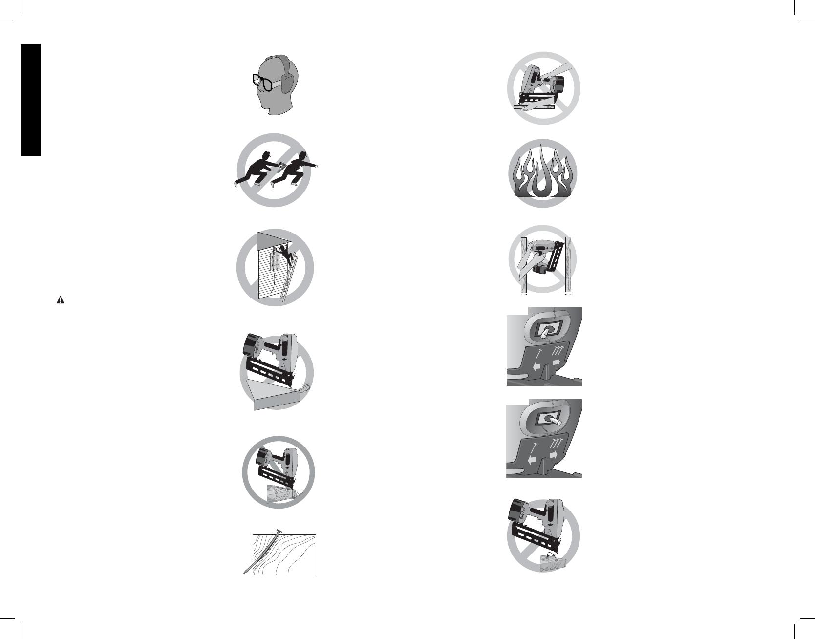
• Do not point the tool at co-workers
or yourself at any time. No horseplay!
Work safe! Respect the tool as a working
implement. (Fig. B)
• Keep bystanders, children, and visitors
away while operating a power tool.
Distractions can cause you to lose control.
When the tool is not in use, it should
be locked in a safe place out of reach of
children.
• Do not carry the tool from place to
place holding the trigger. Accidental
discharge could result.
• Always use contact trip lock-off when
tool is not in immediate use. Using the
contact trip lock-off will prevent accidental
discharge.
• Do not overreach. Maintain proper
footing and balance at all times. (Fig. C)
• Use the tool only for its intended
use. Do not discharge fasteners into
open air, concrete, stone, extremely
hard woods, knots or any material
• Do not point the tool towards yourself
or anyone nearby. Unexpected triggering
will discharge a fastener causing an injury.
• Do not actuate the tool unless the tool
is placed firmly against the workpiece.
If the tool is not in contact with the
workpiece, the fastener may be deflected
away from your target.
• Disconnect the tool from the power
source when the fastener jams in the
tool. While removing a jammed fastener,
the tacker may be accidentally activated if
it is plugged in.
• Use caution while removing a jammed
fastener. The mechanism may be under
compression and the fastener may be
forcefully discharged while attempting to
free a jammed condition.
• Do not use this nailer for fastening
electrical cables. It is not designed for
electric cable installation and may damage
the insulation of electric cables thereby
causing electric shock or fire hazards.
Additional Nailer Safety
Warnings
WARNING: When using any nailer, all
safety precautions, as outlined below, should
be followed to avoid the risk of death or
serious injury. Read and understand all
instructions before operating the tool.
• Hold tool by insulated gripping surfaces
when performing an operation where
the cutting tool may contact hidden
wiring. Contact with a “live” wire will make
exposed metal parts of the tool “live” and
shock the operator.
• Actuating tool may result in flying
debris, collation material, or dust
which could harm operator’s eyes.
The operator and all those persons in the
general area should wear safety glasses
with permanently attached side shields.
Approved safety glasses are imprinted with
the characters “Z87.1”. It is the employer’s
responsibility to enforce the use of eye
protection equipment by the tool operator
and other people in the work area. (Fig. A)
• Always wear appropriate personal
hearing and other protection during
use. Under some conditions and duration
of use, noise from this product may
contribute to hearing loss. (Fig. A)
FIG. B
FIG. A
FIG. C
FIG. D
FIG. E
FIG. F
FIG. K
FIG. J
FIG. G
FIG. H
FIG. I
FIG. L
too hard for the fastener to penetrate.
Do not use the body of the tool or top cap
as a hammer. Discharged fasteners may
follow unexpected path and cause injury.
(Figs. D, F)
• Always keep fingers clear of nail track
of magazine to prevent injury from
inadvertent release of the pusher.
(Fig. G)
• Refer to the Maintenance and Repairs
sections for detailed information on the
proper maintenance of the tool.
• Always operate the tool in a clean,
lighted area. Be sure the work surface
is clear of any debris and be careful not
to lose footing when working in elevated
environments such as rooftops.
• Do not drive fasteners near edge of
material. The workpiece may split causing
the fastener to ricochet, injuring you or a
co-worker. Be aware that the nail may follow
the grain of the wood (shiner), causing it to
protrude unexpectedly from the side of the
work material. Drive the chisel point of the
nail perpendicular to the grain to reduce risk
of injury. (Figs. E, F, L)
• Keep hands and body parts clear of
immediate work area. Hold workpiece
with clamps when necessary to keep hands
and body out of potential harm. Be sure
the workpiece is properly secured before
pressing the nailer against the material. The
contact trip may cause the work material to
shift unexpectedly. (Fig. G)
• Do not use tool in the presence of
flammable dust, gases or fumes. The
tool may produce a spark that could ignite
gases causing a fire. Driving a nail into
another nail may also cause a spark. (Fig. H)
• Keep face and body parts away from
back of the tool cap when working in
restricted areas. Sudden recoil can result
in impact to the body, especially when
nailing into hard or dense material. (Fig. I)
• Grip tool firmly to maintain control while
allowing tool to recoil away from work
surface as fastener is driven. In Bump
mode, if contact trip is allowed to recontact
work surface before trigger is released, an
unwanted fastener will be fired.
• Choice of triggering method is
important. Check the manual for triggering
options.


