Page is loading ...

OPERATOR’S MANUAL
MANUEL D’UTILISATION
MANUAL DEL OPERADOR
16 GAUGE STRAIGHT
FINISH NAILER
CALIBRE 16, CLOUSEUSE DE
FINITION DROITE
CALIBRE 16, CLAVADORA DE
ACABADO RECTA
YN250SFD
Cette produit a été conçue et fabriquée conformément aux strictes
normes de fiabilité, simplicité d’emploi et sécurité d’utilisation.
Correctement entretenu, cet outil vous donnera des années de
fonctionnement robuste et sans problème.
AVERTISSEMENT : Pour réduire les risques de
blessures, l’utilisateur doit lire et veiller à bien comprendre le
manuel d’utilisation avant d’employer ce produit.
Merci de votre achat.
Su producto ha sido diseñado y fabricado de conformidad con
nuestras estrictas normas para brindar fiabilidad, facilidad de
uso y seguridad para el operador. Con el debido cuidado, le
brindará muchos años de sólido funcionamiento y sin problemas.
ADVERTENCIA: Para reducir el riesgo de lesiones,
el usuario debe leer y comprender el manual del operador antes
de usar este producto.
Le agradecemos su compra.
CONSERVER CE MANUEL POUR
FUTURE RÉFÉRENCE
GUARDE ESTE MANUAL PARA
FUTURAS CONSULTAS
SAVE THIS MANUAL FOR FUTURE REFERENCE
Your product has been engineered and manufactured to our high standard for dependability, ease of operation, and opera-
tor safety. When properly cared for, it will give you years of rugged, trouble-free performance.
WARNING: To reduce the risk of injury, the user must read and understand the operator’s manual before using
this product.
Thank you for your purchase.

2 — English
Introduction ..................................................................................................................................................................... 2
Warranty .......................................................................................................................................................................... 2
General Safety Rules ....................................................................................................................................................... 3
Specific Safety Rules ....................................................................................................................................................4-5
Symbols ........................................................................................................................................................................... 6
Glossary of Terms ............................................................................................................................................................ 7
Features ........................................................................................................................................................................... 8
Assembly ......................................................................................................................................................................... 8
Operation ....................................................................................................................................................................9-11
Maintenance ............................................................................................................................................................. 12-13
Accessories ................................................................................................................................................................... 13
Troubleshooting ............................................................................................................................................................. 14
Figure numbers (illustrations) ...................................................................................................................................15-16
Parts Ordering / Service ................................................................................................................................... Back page
TABLE OF CONTENTS
INTRODUCTION
This product has many features for making its use more pleasant and enjoyable. Safety, performance, and dependability
have been given top priority in the design of this product making it easy to maintain and operate.
WARRANTY
RYOBI® POWER TOOL - LIMITED THREE YEAR WARRANTY AND 90 DAY EXCHANGE POLICY
One World Technologies, Inc., warrants its RYOBI®
power tools with the following conditions:
90-DAY EXCHANGE POLICY: During the first 90 days after date of purchase, you may either request service under this
warranty or you may exchange any RYOBI® power tool which does not work properly due to defective workmanship or
materials by returning the power tool to the dealer from which it was purchased. To receive a replacement power tool or
requested warranty service, you must present proof of purchase and return all original equipment packaged with the original
product. The replacement power tool will be covered by the limited warranty for the balance of the three year period from
the date of the original purchase.
WHAT THIS WARRANTY COVERS: This warranty covers all defects in workmanship or materials in your RYOBI® power
tool for a period of three years from the date of purchase. With the exception of batteries, power tool accessories are war-
ranted for ninety (90) days. Batteries are warranted for three years.
HOW TO GET SERVICE: Just return the power tool, properly packaged and postage prepaid, to an Authorized Service
Center. You can obtain the location of the Service Center nearest you by contacting a service representative at One
World Technologies, Inc., P.O. Box 1207, Anderson, SC 29622-1207, by calling 1-800-525-2579 or by logging on to
www.ryobitools.com. When you request warranty service, you must also present proof of purchase documentation, which
includes the date of purchase (for example, a bill of sale). We will repair any faulty workmanship, and either repair or replace
any defective part, at our option. We will do so without any charge to you. We will complete the work in a reasonable time,
but, in any case, within ninety (90) days or less.
WHAT’S NOT COVERED: This warranty applies only to the original purchaser at retail and may not be transferred. This
warranty only covers defects arising under normal usage and does not cover any malfunction, failure or defects resulting
from misuse, abuse, neglect, alteration, modification or repairs by other than Authorized Service Centers. One World Tech-
nologies, Inc. makes no warranties, representations or promises as to the quality or performance of its power tools other
than those specifically stated in this warranty.
ADDITIONAL LIMITATIONS: Any implied warranties granted under state law, including warranties of merchantability or
fitness for a particular purpose, are limited to three years from the date of purchase. One World Technologies, Inc. is not
responsible for direct, indirect, or incidental damages, so the above limitations and exclusions may not apply to you. This
warranty gives you specific legal rights, and you may also have other rights which vary from state to state.

3 — English
DANGER:
READ AND UNDERSTAND TOOL LABELS AND
MANUAL. Failure to follow warnings could result in
DEATH or SERIOUS INJURY.
SAVE THESE INSTRUCTIONS
WORK AREA
Keep your work area clean and well lit. Cluttered
benches and dark areas invite accidents.
Do not operate power tools in explosive atmospheres,
such as in the presence of flammable liquids, gases,
or dust. Power tools create sparks which may ignite the
dust or fumes.
Keep bystanders, children, and visitors away while
operating a power tool. Distractions can cause you to
lose control.
PERSONAL SAFETY
Eye protection which conforms to ANSI specifications
and provides protection against flying particles both
from the FRONT and SIDE should ALWAYS be worn
by the operator and others in the work area when
loading, operating or servicing this tool. Eye protection
is required to guard against flying fasteners and debris,
which could cause severe eye injury.
The employer and/or user must ensure that proper
eye protection is worn. We recommend Wide Vision
Safety Mask for use over eyeglasses or standard safety
glasses that provide protection against flying particles
both from the front and side. Always use eye protection
which is marked to comply with ANSI Z87.1.
Additional safety protection will be required in some
environments. For example, the working area may
include exposure to noise level which can lead to hearing
damage. The employer and user must ensure that any
necessary hearing protection is provided and used by the
operator and others in the work area. Some environments
will require the use of head protection equipment. When
required, the employer and user must ensure that head
protection conforming to ANSI Z89.1-1997 is used.
Stay alert, watch what you are doing and use common
sense when operating a power tool. Do not use tool
while tired or under the influence of drugs, alcohol,
or medication. A moment of inattention while operating
power tools may result in serious personal injury.
Dress properly. Do not wear loose clothing or jewelry.
Contain long hair. Keep your hair, clothing, and gloves
away from moving parts. Loose clothes, jewelry, or long
hair can be caught in moving parts.
Keep fingers away from trigger when not driving
fasteners to avoid accidental firing.
Do not overreach. Keep proper footing and balance
at all times. Proper footing and balance enables better
control of the tool in unexpected situations.
Use safety equipment. Always wear eye protection.
Dust mask, nonskid safety shoes, hard hat, or hearing
protection must be used for appropriate conditions.
Do not use on a ladder or unstable support. Stable
footing on a solid surface enables better control of the
tool in unexpected situations.
TOOL USE AND CARE
Do not force tool. Use the correct tool for your
application. The correct tool will do the job better and
safer at the rate for which it is designed.
Do not use tool if trigger does not actuate properly.
Any tool that cannot be controlled with the trigger is
dangerous and must be repaired.
Check operation of the workpiece contact mechanism
frequently. Do not use the tool if the workpiece contact
mechanism is not working correctly as accidental driving
of a fastener may result. Do not interfere with the proper
operation of the workpiece contact mechanism.
Store idle tools out of the reach of children and other
untrained persons. Tools are dangerous in the hands of
untrained users.
Maintain tools with care. Follow maintenance
instructions. Properly maintained tools are easier to
control.
Check for misalignment or binding of moving parts,
breakage of parts, and any other condition that may
affect the tool’s operation. If damaged, have the tool
serviced before using. Many accidents are caused by
poorly maintained tools.
Use only fasteners that are recommended for your
model.
Keep the tool and its handle dry, clean and free from oil
and grease. Always use a clean cloth when cleaning. Never
use brake fluids, gasoline, petroleum-based products, or
any strong solvents to clean your tool. Following this rule
will reduce the risk of loss of control and deterioration of
the enclosure plastic.
SERVICE
Tool service must be performed only by qualified
repair personnel. Service or maintenance performed by
unqualified personnel may result in a risk of injury.
When servicing a tool, use only identical replacement
parts. Follow instructions in the Maintenance section
of this manual. Use of unauthorized parts or failure to
follow Maintenance instructions may create a risk of injury.
GENERAL SAFETY RULES

4 — English
SPECIFIC SAFETY RULES
Know your pneumatic tool. Read operator’s manual
carefully. Learn its applications and limitations, as well
as the specific potential hazards related to this tool.
Following this rule will reduce the risk of electric shock,
fire, or serious injury.
Always wear safety glasses with side shields.
Everyday glasses have only impact resistant lenses. They
are NOT safety glasses. Following this rule will reduce
the risk of eye injury.
Protect your lungs. Wear a face or dust mask if the
operation is dusty. Following this rule will reduce the risk
of serious personal injury.
Protect your hearing. Wear hearing protection during
extended periods of operation. Following this rule will
reduce the risk of serious personal injury.
Make sure the hose is free of obstructions or snags.
Entangled or snarled hoses can cause loss of balance or
footing and may become damaged.
Use the tool only for its intended use. Do not discharge
fasteners into open air.
Use the pneumatic tool only for the purpose for which
it was designed.
Use only the fasteners recommended for this tool.
Use of the wrong fasteners could result in poor fastener
feeding, jammed fasteners, and nails leaving the tool at
erratic angles. If fasteners are not feeding smoothly and
properly, discontinue their use immediately. Jammed
and improperly feeding fasteners could result in serious
personal injury.
Never use this tool in a manner that could cause a
fastener to be directed toward anything other than
the workpiece.
Do not use the tool as a hammer.
Always carry the tool by the handle. Never carry the
tool by the air hose.
Do not alter or modify this tool from the original design
or function without approval from the manufacturer.
Always be aware that misuse and improper handling
of this tool can cause injury to yourself and others.
Never clamp or tape the trigger or workpiece contact
in an actuated position.
Never leave a tool unattended with the air hose
attached.
Do not operate this tool if it does not contain a legible
warning label.
Do not continue to use a tool that leaks air or does
not function properly.
OPERATION
Always assume that the tool contains fasteners.
Do not carry the tool from place to place holding the
trigger. Accidental discharge could result.
Always handle the tool with care:
• Respect the tool as a working implement.
• Neverengageinhorseplay.
• Neverpullthetriggerunlessnoseisdirectedtoward
the work.
• Keepothersasafedistancefromthetoolwhiletoolisin
operation as accidental actuation may occur, possibly
causing injury.
Choice of triggering method is important. Check
manual for triggering options.
Pneumatic tools are designed for single-hand use. Do
not hold the tool by the front of the magazine. Do not put
hands, head, or other parts of your body near the bottom
of the magazine where the nail exits the tool, as serious
personal injury could result.
Do not point the tool toward yourself or anyone whether
it contains fasteners or not.
Do not actuate the tool unless you intend to drive a
fastener into the workpiece.
Always ensure that the workpiece contact is fully
positioned on the workpiece. Positioning the work
contact element only partially on the workpiece could
cause the fastener to miss the workpiece completely and
result in serious personal injury.
Do not drive fasteners near edge of material. The
workpiece may split causing the fastener to ricochet,
injuring you or a co-worker. Be aware that the nail may
follow the grain of the wood, causing it to protrude
unexpectedly from the side of the work material.
Keep hands and body parts clear of immediate work
area. Hold workpiece with clamps when necessary to
keep hands and body out of potential harm. Be sure the
workpiece is properly secured before pressing the nailer
against the material. The workpiece contact may cause
the work material to shift unexpectedly.
Keep face and body parts away from back of the tool
cap when working in restricted areas. Sudden recoil
can result in impact to the body, especially when nailing
into hard or dense material.

5 — English
SPECIFIC SAFETY RULES
During normal use the tool will recoil immediately
after driving a fastener. This is a normal function of
the tool. Do not attempt to prevent the recoil by holding
the nailer against the work. Restriction to the recoil can
result in a second fastener being driven from the nailer.
Grip the handle firmly and let the tool do the work. Failure
to heed this warning can result in serious personal injury.
Do not drive fasteners on top of other fasteners or with
the tool at an overly steep angle as this may cause
deflection of fasteners which could cause injury.
Do not drive fasteners close to the edge of the
workpiece as the wood may split, allowing the fastener
to be deflected possibly causing injury.
AIR SUPPLY AND CONNECTIONS
Do not use oxygen, combustible gases or bottled gases
as a power source for this tool as tool will explode,
possibly causing injury or death.
Do not use with an air compressor which can potentially
exceed 200 psi, as tool may burst, possibly causing
injury.
The connector on the tool must not hold pressure when
air supply is disconnected. If an incorrect fitting is used,
the tool can remain charged with air after disconnecting
and thus will be able to drive a fastener even after the air
line is disconnected, possibly causing injury.
Always disconnect air supply:
• Beforemakingadjustments
• Whenservicingthetool
•Whenclearingajam
• Whentoolisnotinuse
• Whenmovingtoadifferentworkarea,asaccidental
actuation may occur, possibly causing injury.
LOADING TOOL
Do not load the tool with fasteners when any one of
the operating controls is activated.
When loading tool:
Never place a hand or any part of body in fastener
discharge area of tool.
Never point tool at anyone.
Do not pull the trigger or depress the workpiece
contact as accidental actuation may occur, possibly
causing injury.
SAVE THESE INSTRUCTIONS
Refer to them frequently and use them to instruct others
who may use this tool. If you loan someone this tool, loan
them these instructions also.
CALIFORNIA PROPOSITION 65
WARNING:
This product and some dust created by power sanding, sawing, grinding, drilling, and other construction activities may
contain chemicals, including lead, known to the State of California to cause cancer, birth defects, or other reproductive
harm. Wash hands after handling.
Some examples of these chemicals are:
• lead from lead-based paints,
• crystalline silica from bricks and cement and other masonry products and,
• arsenic and chromium from chemically treated lumber.
Your risk from exposure to these chemicals varies, depending on how often you do this type of work. To reduce your
exposure, work in a well-ventilated area and with approved safety equipment, such as dust masks that are specially
designed to filter out microscopic particles.
6 — English
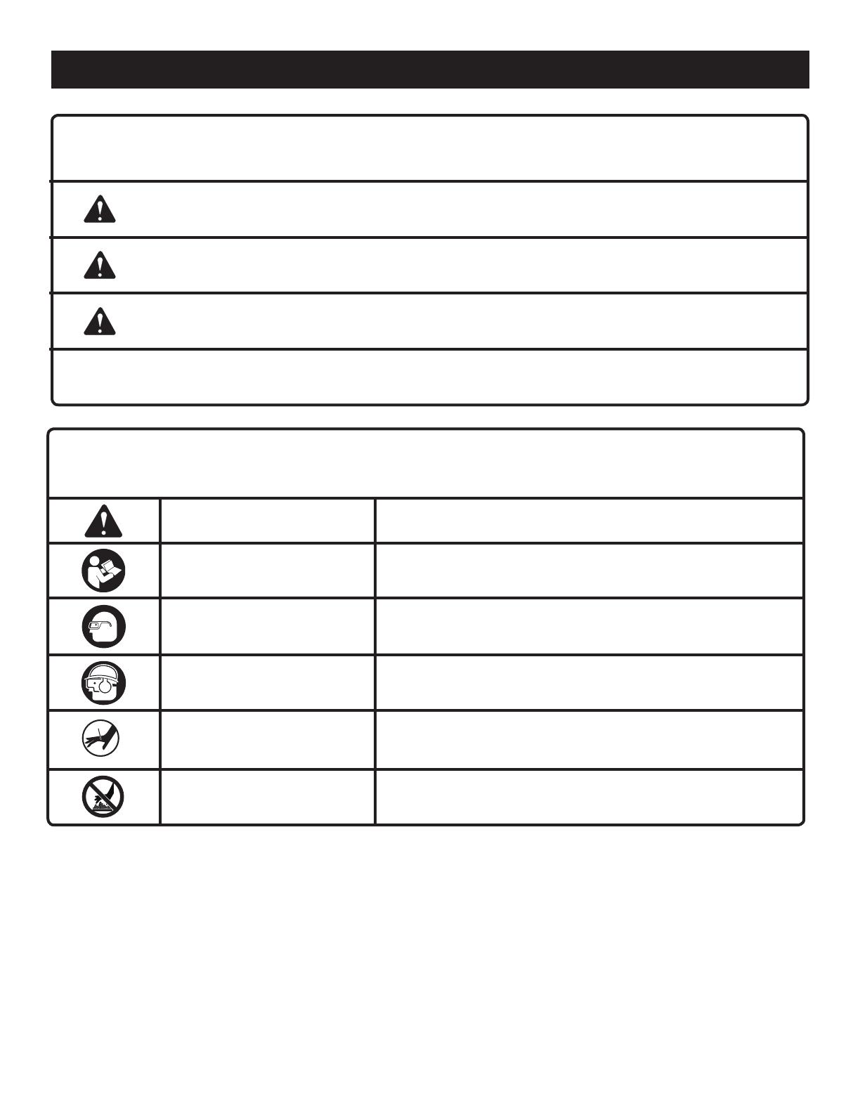
Some of the following symbols may be used on this product. Please study them and learn their meaning. Proper
interpretation of these symbols will allow you to operate the product better and safer.
SYMBOL NAME DESIGNATION/EXPLANATION
Safety Alert Indicates a potential personal injury hazard.
Read Operator’s Manual
To reduce the risk of injury, user must read and understand
operator’s manual before using this product.
Eye Protection
Always use eye protection with side shields or goggles marked to
comply with ANSI Z87.1.
Eye, Ear, and Head Protection
Always wear other personal protective equipment such as hearing
protection and a hard hat when needed.
KeepHandsAway Keephandsandbodyawayfromthedischargeareaofthetool.
Hot Surface
To reduce the risk of injury or damage, avoid contact with any hot
surface.
SYMBOLS
The following signal words and meanings are intended to explain the levels of risk associated with this product.
SYMBOL SIGNAL MEANING
DANGER:
Indicates an imminently hazardous situation, which, if not avoided, will result
in death or serious injury.
WARNING:
Indicates a potentially hazardous situation, which, if not avoided, could result
in death or serious injury.
CAUTION:
Indicates a potentially hazardous situation, which, if not avoided, may result in
minor or moderate injury.
CAUTION:
(Without Safety Alert Symbol) Indicates a situation that may result in property
damage.

7 — English
GLOSSARY OF TERMS
Activate (operating controls)
To move an operating control so that it is in a position that
allows the tool to be actuated or that satisifes one require-
ment for the tool to be actuated.
Actuate (tool)
To cause movement of the tool component(s) intended to
drive a fastener.
Air inlet port
In an air tool, the opening to which the compressed air supply
is connected, usually by means of a threaded fitting.
Fastener
A staple, pin, brad, nail, or other fastening device which is
designed and manufactured for use in the tools within the
scope of this standard.
Jam
An obstruction in the feed or drive areas of the tool.
Maximum air pressure
The maximum allowable pressure of the compressed air, as
specified by the manufacturer, for operating a tool.
Operating control
A control that separately, or as part of an actuation system,
can cause the actuation of a tool.
Single sequential actuation
An actuation system in which there is more than one operat-
ing control and the operating controls must be activated in
a specific sequence to actuate the tool. Additional actuation
can occur when a specific operating control, other than a
workpiece contact, is released and re-activated.
Trigger
A tool operating control activated by a tool operator’s fingers.
Workpiece
The intended object into which a fastener is to be driven
by a tool.
Workpiece contact
An operating control element or assembly on the tool in-
tended to be activated by the material to be fastened.
8 — English
PACKING LIST
Straight Finish Nailer
Oil
Sample Fasteners
Eye Protection
HexKeys(3mmand4mm)
Operator’s Manual
WARNING:
If any parts are damaged or missing do not operate this
product until the parts are replaced. Use of this product
with damaged or missing parts could result in serious
personal injury.
WARNING:
Do not attempt to modify this product or create acces-
sories not recommended for use with this product. Any
such alteration or modification is misuse and could result
in a hazardous condition leading to possible serious
personal injury.
FEATURES
UNPACKING
This product has been shipped completely assembled.
Carefully remove the product and any accessories from
the box. Make sure that all items listed in the packing list
are included.
WARNING:
Do not use this product if it is not completely assembled
or if any parts appear to be missing or damaged. Use of
a product that is not properly and completely assembled
could result in serious personal injury.
Inspect the product carefully to make sure no breakage
or damage occurred during shipping.
Do not discard the packing material until you have carefully
inspected and satisfactorily operated the product.
If any parts are damaged or missing, please call
1-800-525-2579 for assistance.
ASSEMBLY
PRODUCT SPECIFICATIONS
Operating Pressure.............................................70-120 psi
Fastener Type ..................................... 16 gauge finish nails
Fastener Range ..........................................1 in. to 2-1/2 in.
Magazine Capacity ................................................ 110 nails
Air Consumption............................ 0.05 ft
3
/cycle at 100 psi
Air Inlet .............................................................. 1/4 in. NPT
Weight ........................................................................ 4 lbs.
KNOW YOUR STRAIGHT FINISH NAILER
See Figure 1, page 15.
The safe use of this product requires an understanding of
the information on the product and in this operator’s manual
as well as a knowledge of the project you are attempting.
Before use of this product, familiarize yourself with all
operating features and safety rules.
ADJUSTABLE EXHAUST
The exhaust can be adjusted to a variety of positions de-
pending on operator preference.
DEPTH OF DRIVE ADJUSTMENT
The tool-free depth of drive adjustment lets the operator
select precise driving depth of the fastener.
JAM RELEASE
A tool-free jam release is provided for ease in clearing infre-
quent jams.
NO-MAR NOSEPIECE
The no-mar nosepiece prevents marring and denting when
using the tool on softer woods.
TOP-LOADING MAGAZINE
The top-loading magazine offers quick three-step reloading
of fasteners.
TRIGGER
Your straight finish nailler has a single sequential trigger for
precise fastener placement.
9 — English
WARNING:
Do not allow familiarity with this product to make you
careless. Remember that a careless fraction of a second is
sufficient to inflict serious injury.
WARNING:
Always wear eye protection with side shields or goggles
marked to comply with ANSI Z87.1. Failure to do so could
result in fluids entering your eyes resulting in possible
serious injury.
WARNING:
Disconnect the tool from the air supply before leaving the
work area, moving the tool to another location, or handing
the tool to another person. Failure to do so could result
in serious personal injury.
APPLICATIONS
You may use this product for the purpose listed below:
Finish and Trim (Interior and exterior)
Door & Window Casing
Door Jambs
Baseboard
Crown Molding
Cabinetry
Cap and Shoe Molding
Molding
Staircases
Door and Window Trim
Chair Rail
Brickmold
Hardwood Flooring
Paneling
Furniture
WARNING:
Always wear eye protection. Eye protection does not fit
all operators in the same way. Make sure the eye protec-
tion chosen has side shields or provides protection from
flying debris both from the front and sides.
OPERATION
PREPARING THE TOOL FOR USE
See Figure 2, page 15.
Under normal use conditions, the tool should be lubricated
before connecting the tool to an air supply. Add air tool oil
into the air fitting on the tool once daily with minimal use,
or twice a day with heavy use. Only a few drops of oil at a
time is necessary. Too much oil will only collect inside the
tool and will be noticeable in the exhaust cycle.
Before connecting the tool, check the air compressor
gauge to be sure it is functioning within the proper range of
70-120 psi.
NO-MAR NOSEPIECE
See Figure 3, page 15.
The no-mar nosepiece attached to the workpiece contact
of the tool helps prevent marring and denting when working
with softer woods.
WARNING:
Disconnect the tool from the air supply before removing
or replacing the no-mar nosepiece. Failure to do so could
result in serious personal injury.
The no-mar nosepiece can be removed by pulling it down
and away from the nose. To replace the no-mar nosepiece
fit it into place over the workpiece contact and push up at
the back to reseat.
ADJUSTING THE EXHAUST
See Figure 4, page 15.
The adjustable exhaust on the end cap of the tool allows the
operator to direct the exhaust according to operator prefer-
ence. To adjust, turn the exhaust cap until the exhaust blows
in the desired direction.
CONNECTING THE TOOL TO AN AIR SUPPLY
See Figure 5, page 15.
DANGER:
Do not use oxygen, combustible gases or bottled gases
as a power source for this tool. The tool will explode and
cause death or serious injury.
This tool is designed to operate on clean, dry compressed
air at regulated pressures between 70 and 120 psi . The cor-
rect air pressure is the lowest pressure that will do the job.
NOTE: Air pressure that is higher than 120 psi may damage
the tool.
The tool must have an air fitting that allows all pressure
to discharge from the tool when the air hose connector is
disconnected.

10 — English
WARNING:
Always use an air fitting that discharges all the com-
pressed air in the tool at the time the air fitting and air
hose connector is disconnected. Using an air fitting that
does not discharge the compressed air could cause un-
intended operation and serious personal injury.
WARNING:
Do not climb rigging or scaffolding while carrying a tool
that is connected to an air hose. Doing so could result in
serious personal injury.
Connect the tool to the air supply with a 1/4 in. female quick
connector.
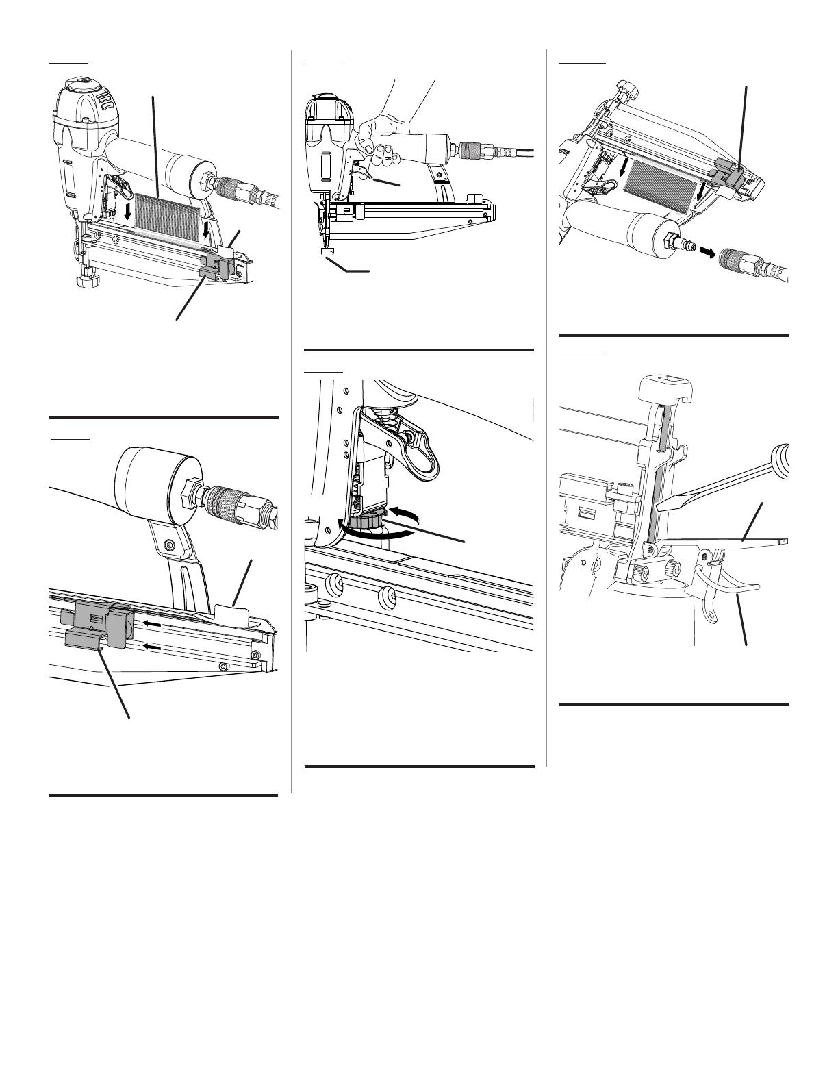
LOADING THE TOOL WITH NAILS
See Figures 6 - 7, page 16.
Connect the tool to the air supply.
WARNING:
The tool’s driving mechanism may cycle when the tool
is first connected to the air supply. Always connect the
tool to the air supply before loading nails to prevent injury
from unintended cycling. Always make sure the tool’s
magazine is empty at the beginning of each work ses-
sion, before connecting to an air supply.
WARNING:
Keep the tool pointed away from yourself and others
when loading nails. Failure to do so could result in pos-
sible serious personal injury.
WARNING:
Use only the nails recommended for use with this tool.
The use of any other nails can result in tool malfunction,
leading to serious injuries.
WARNING:
Never load nails with the workpiece contact or trigger
activated. Doing so could result in possible serious per-
sonal injury.
Slide the pusher all the way to the rear of the magazine
until it locks into place.
With the nose of the tool pointed away from you, feed
a strip of nails into the magazine. Be sure the nails are
pointed downward as shown.
Depress the pusher release located on the top of the
magazine to allow the pusher to move the nails up to the
driving mechanism. The pusher will stop when it rests
against the end of the nail strip.
DRIVING A FASTENER
See Figure 8, page 16.
WARNING:
Never wedge or hold back the workpiece contact mecha-
nism during operation of the tool. Doing so could result
in possible serious injury.
SINGLE SEQUENTIAL ACTUATION
Single sequential actuation provides accurate fastener
placement.
Connect the tool to the air supply.
Grip the tool firmly to maintain control. Position the nose
of the tool onto the work surface.
Push the tool against the work surface to depress the
workpiece contact.
Pull the trigger to drive a fastener.
Allow the tool to recoil away from the work surface as the
fastener is driven.
WARNING:
During normal use the tool will recoil immediately
after driving a fastener. This is a normal function of
the tool. Do not attempt to prevent the recoil by holding
the nailer against the work. Restriction to the recoil can
result in a second fastener being driven from the nailer.
Grip the handle firmly, let the tool do the work, and do
not place second hand on top of tool or near exhaust at
any time. Failure to heed this warning can result in seri-
ous personal injury.
OPERATION
11 — English
OPERATION
SETTING THE AIR PRESSURE
The amount of air pressure required will depend on the size
of the nail and the workpiece material.
Begin testing the depth of drive by driving a test nail into
the same type of workpiece material used for the actual job.
Drive a test nail with the air pressure set at 90-95 psi. Raise
or lower the air pressure to find the lowest setting that will
perform the job with consistent results.
It may be possible to achieve the desired depth with air
pressure adjustments alone. If finer adjustments are needed,
use the drive depth adjustment on the tool.
DRIVE DEPTH ADJUSTMENT
See Figure 9, page 16.
The driving depth of the nail may be adjusted. It is advisable
to test the depth on a scrap workpiece to determine the
required depth for the application.
To determine depth of drive, first adjust the air pressure and
drive a test nail. To achieve the desired depth, use the drive
depth adjustment on the tool.
Disconnect the tool from the air supply.
Turn the depth selector left or right to change the driving
depth.
Reconnect the tool to the air supply.
Drive a test nail after each adjustment until the desired
depth is set.
WARNING:
Disconnect the tool from the air supply before removing
nails. Failure to do so could result in serious personal
injury.
REMOVING NAILS FROM THE TOOL
See Figure 10, page 16.
Disconnect the tool from the air supply.
Slide the pusher all the way to the rear of the magazine
until it locks into place.
NOTE: Always keep fingers clear of nail track of magazine
to prevent injury from unintended release of the pusher.
Tilt the tool as shown so that the nails slide out of the
magazine.
WARNING:
Disconnect the tool from the air supply before clearing a
jammed fastener. Failure to do so could result in serious
personal injury.
CLEARING A JAMMED FASTENER
See Figure 11, page 16.
If a nail or fastener becomes jammed in the tool, disconnect
the air hose and keep the tool pointed away from you while
clearing the jam.
Disconnect the tool from the air supply.
Remove fasteners from the tool.
Pulluponthelatchandopenthejamrelease.
Insert a flat blade screwdriver into the driving mechanism
and push the driver mechanism back, freeing the fastener
jam.
Remove the bent fastener.
Close the jam release and latch.
Reconnect the tool to the air supply.
Reinstall fasteners.
12 — English
MAINTENANCE
WARNING:
When servicing, use only identical replacement parts.
Use of any other parts could create a hazard or cause
product damage.
WARNING:
Always wear eye protection with side shields or goggles
marked to comply with ANSI Z87.1. Failure to do so could
result in fluids entering your eyes resulting in possible
serious injury.
WARNING:
Disconnect the tool from the air supply before perform-
ing maintenance. Failure to do so could result in serious
personal injury.
GENERAL MAINTENANCE
Avoid using solvents when cleaning plastic parts. Most
plastics are susceptible to damage from various types of
commercial solvents and may be damaged by their use. Use
clean cloths to remove dirt, dust, oil, grease, etc.
WARNING:
Do not at any time let brake fluids, gasoline, petroleum-
based products, penetrating oils, etc., come in contact
with plastic parts. Chemicals can damage, weaken or
destroy plastic which may result in serious personal injury.
LUBRICATION
Frequent, but not excessive, lubrication is required for
best performance. Oil for pneumatic fastening tools added
through the air line connection will lubricate the internal parts.
Do not use detergent oil or additives as these lubricants will
cause accelerated wear to the seals and bumpers in the
tool, resulting in poor tool performance and frequent tool
maintenance.
COLD WEATHER OPERATION
For cold weather operation, near and below freezing, the
moisture in the air line may freeze and prevent tool operation.
We recommend the use of air tool lubricant or permanent
antifreeze (ethylene glycol) as a cold weather lubricant.
CAUTION:
Do not store tools in a cold weather environment to pre-
vent frost or ice formation on the tools’ operating valves
and mechanisms that could cause tool failure and pos-
sible injury.
NOTE: Some commercial air line drying liquids are harmful
to “O” rings and seals. Do not use these low temperature
air dryers without checking compatibility.
AIR SUPPLY PRESSURE AND VOLUME
Air volume is as important as air pressure. The air volume
supplied to the tool may be inadequate because of under-
size fittings and hoses, or from the effects of dirt and water
in the system. Restricted air flow will prevent the tool from
receiving an adequate volume of air, even though the pres-
sure reading is high. The results will be a slow operation or
reduced driving power. Before evaluating tool problems for
these symptoms, trace the air supply from the tool to the
supply source for restrictive connectors, low points contain-
ing water and anything else that would prevent full volume
flow of air to the tool.

13 — English
MAINTENANCE
REQUIRED DAILY CHECKLIST
Disconnect the air supply from the tool and remove all
fasteners.
Check all screws, nuts, bolts, and pins on the tool. If
any of these are loose, they must be tightened with the
appropriate size wrench.
Press the workpiece contact against a workpiece to
ensure that it moves smoothly.
With the workpiece contact depressed, pull the trigger.
The trigger should move smoothly, without binding.
While the tool is not loaded, connect the appropriate air
supply (at 70 psi) to the tool.
Without pulling the trigger, press the workpiece contact
against a workpiece several times. The tool must not
operate. No air should leak from the tool.
With the workpiece contact not engaged on the
workpiece, point the tool down and away and pull the
trigger several times. Hold the trigger in this position for
a minimum of 5 seconds. The tool must not operate.
Press the workpiece contact firmly against the workpiece.
Pull the trigger. The tool must operate.
With the workpiece contact still depressed, release the
trigger. The driver must return to its up position.
If the tool successfully meets all the requirements in this
checklist, it is ready for use. Load the proper fasteners
for the desired application.
Set the depth of drive according to the Drive Depth
Adjustment section in this manual. Repeat this checklist
before using the tool each day, or if the tool is dropped
or damaged in any way.
ACCESSORIES
WARNING:
Current attachments and accessories available for use with this tool are listed above. Do not use any attachments or ac-
cessories not recommended by the manufacturer of this tool. The use of attachments or accessories not recommended
can result in serious personal injury.
To order parts and maintenance kits, call 1-800-525-2579.
OverhaulMaintenanceKit ................................................................................................................................079025001050
DriverMaintenanceKit .....................................................................................................................................079025001051
DriverAssemblyKit ..........................................................................................................................................079025001701
TriggerValveAssemblyKit ...............................................................................................................................079025001700
WrenchKit ........................................................................................................................................................079024001023
Oil .....................................................................................................................................................................079002001113

14 — English
TROUBLESHOOTING
Air leak near the top of the tool or
in the trigger area
PROBLEM POSSIBLE CAUSE SOLUTION
Loose screws
Worn or damaged O-rings or
seals
Tool does nothing or operates
sluggishly
Tool jams frequently
Tighten screws
InstallOverhaulKit
Inadequate air supply
Inadequate lubrication
Worn or damaged O-rings or bumper
InstallOverhaulKit
Verify adequate air supply
Lubricate tool
InstallOverhaulKit
Air leak near the bottom of the tool Worn or damaged O-rings or bumper
Incorrect fasteners
Damaged fasteners
Loose magazine
Dirty magazine
Worn or damaged driver
Verify that fasteners are the correct type
and length
Replace fasteners
Tighten screws
Clean magazine
InstallDriverMaintenanceKit
NOTE: FIGURES (ILLUSTRATIONS) START ON PAGE 15 AFTER
FRENCH AND SPANISH LANGUAGE SECTIONS.
16
Fig. 8
Fig. 7
A - Pusher release
relâcher l’poussoir, soltar el empujador)
B - Pusher (poussoir, empujador)
B
A
Fig. 6
A - Nails (clous, clovos)
B - Pusher release (relâcher l’poussoir, soltar el
empujador)
C - Pusher (poussoir, empujador)
A
B
C
Fig. 9
Fig. 11
Fig. 10
A - Jam release (déblocage, soltador)
B - Latch (loquest, pestillo)
A
B
A - Pusher (poussoir, empujador)
A
A - Trigger (gâchette, gatillo)
B - Workpiece contact (contact de
declénchement, disparador de contacto)
A - Drive depth adjustment (pour augmenter la
profondeur, boquilla)
B - To increase depth (réglage de porfondeur
d’enfoncement, boquilla)
C - To decrease depth (pour réduire la
profondeur, alambre)
B
C
B
A
A

ONE WORLD TECHNOLOGIES, INC.
1428 Pearman Dairy Road, Anderson, SC 29625
A subsidiary of Techtronic Industries Co., Ltd. • Phone 1-800-525-2579
États-Unis, Téléphone 1-800-525-2579 • USA, Teléfono 1-800-525-2579
OTC: TTNDY
www.ryobitools.com
• PIEZAS DE REPUESTO Y SERVICIO
Antes de solicitar servicio técnico o comprar piezas de repuesto, obtenga su modelo y número de serie de la placa de datos del
producto.
• NÚMERO DE MODELO ______________________
• NÚMERO DE SERIE ______________________
• CÓMO OBTENER PIEZAS DE REPUESTO:
Las piezas de repuesto se pueden comprar en nuestro sitio en la red mundial, en la dirección www.ryobitools.com o llamando al
1-800-525-2579. Las piezas de repuesto también se pueden obtener en uno de nuestros Centros de Servicio Autorizados.
• CÓMO LOCALIZAR UN CENTRO DE SERVICIO AUTORIZADO:
Puede encontrar los Centros de Servicio Autorizados visitando nuestro sitio en la red mundial, en la dirección www.ryobitools.
com o llamando al 1-800-525-2579.
• CÓMO OBTENER SERVICIO O ASISTENCIA TÉCNICA AL CONSUMIDOR:
Para obtener Servicio o Asistencia Técnica al Consumidor, sírvase comunicarse con nosotros llamando al 1-800-525-2579.
988000-678
8-16-11 (REV:01)
• PARTS AND SERVICE
Prior to requesting service or purchasing replacement parts, please obtain your model and serial number from the
product data plate.
• MODEL NUMBER ____________________
• SERIAL NUMBER ____________________
• HOW TO OBTAIN REPLACEMENT PARTS:
Replacement parts can be purchased online at www.ryobitools.com or by calling 1-800-525-2579. Replacement
parts can also be obtained at one of our Authorized Service Centers.
• HOW TO LOCATE AN AUTHORIZED SERVICE CENTER:
Authorized Service Centers can be located online at www.ryobitools.com or by calling 1-800-525-2579.
• HOW TO OBTAIN CUSTOMER OR TECHNICAL SUPPORT:
To obtain Customer or Technical Support please contact us at 1-800-525-2579.
RYOBI is a registered trademark of Ryobi Limited and is used pursuant to a license granted by Ryobi Limited.
OPERATOR’S MANUAL / 16 GAUGE STRAIGHT FINISH NAILER
MANUEL D’UTILISATION /
CALIBRE 16, CLOUSEUSE DE FINITION DROITE
MANUAL DEL OPERADOR /
CALIBRE 16, CLAVADORA DE ACABADO RECTA
• PIÈCES ET SERVICE
Avant de faire la demande de service ou l’achat de pièces de remplacement, veuillez obtenir le numéro de série du modèle à partir
de la plaque de données du produit.
• NUMÉRO DE MODÈLE _____________________
• NUMÉRO DE SÉRIE _____________________
• COMMENT OBTENIR LES PIÈCES DE REMPLACEMENT :
Les pièces de remplacement peuvent être achetées en ligne sur le site www.ryobitools.com ou par téléphone au 1-800-525-2579.
Les pièces de remplacement peuvent être obtenues à un de nos centres de service autorisés.
• COMMENT TROUVER UN CENTRE DE SERVICE AUTORISÉ :
Les centres de service autorisés peuvent être localisés en ligne au www.ryobitools.com ou en téléphonant au 1-800-525-2579.
• COMMENT OBTENIR DE L’AIDE EN CONTACTANT LE SERVICE À LA CLIENTÈLE :
Pour contacter le service à la clientèle pour une question technique ou pour tout autre renseignement, veuillez nous téléphoner
au 1-800-525-2579.
RYOBI est une marque déposée de RYOBI Limited et est utilisée en vertu d’une licence accordée par Ryobi Limited.
RYOBI es una marca registrada de Ryobi Limited y se utiliza conforme a una licencia otorgada por Ryobi Limited.
YN250SFD
YN250SFD
YN250SFD
/