
1 In-wall countdown timer
Rating: 120V/15A/1800W Resistive (Appliance)
120V/8.3A/1000W Tungsten (Incandescent)
1/4HP, Motor: 1000VA, Ballast
Wire connectors Mounting screws
120VAC 60Hz, 15A General Purpose
Electronic Ballast: 500 VA
Cover
OFF
HOUR
8
4
2
1
HOUR
HOUR
HOUR
Contents
In-Wall Auto Shut-Off Electronic Timer
MAPATIM02-01
2019-05-13
Safety Information
WARNING
•
•
TO AVOID FIRE, SHOCK, OR DEATH, TURN OFF POWER AT CIRCUIT BREAKER AND TEST THAT POWER IS
OFF BEFORE WIRING.
TO AVOID OVERHEATING, USE ONLY 14 AWG, 600V, 105ºC WIRE TO CONNECT THIS TIMER.
CAUTION
•
Wattage of lamps or appliances controlled must NOT exceed rated capacity. FOR INDOOR USE ONLY.
1-888-686-0778

NOTE: Neutral wire is required for this timer to function. This timer
is not compatible for 3-wire switches.
A
E
E
D
E
B
F
F
C
Instructions
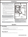
Timer Setting
To set timer, press button sequentially to select one of the four timed delay shut-off settings:
1 hour / 2 hours / 4 hours / 8 hours.
The illuminated LED display indicates which time delay shut-off setting is selected.
Timer starts counting down until desired time setting is reached, and shuts off automatically. “OFF” LED display is illuminated.
Turn power OFF at the circuit breaker or remove the fuse.
Remove existing wall plate and switch, if applicable. Take note of supply
(“hot” (usually black or red)) and neutral wires for future reference.
Ensure neutral (white) wire is present in the junction box. If this wire is
not present, additional wiring arrangements will be needed before
installation can be completed. Consult a qualied electrician.
Strip 3/8 in. of insulation from each wire required for installation.
Connect the green wire (F) from the junction box to the green wire
from the timer.
Connect the white wire (E) from the timer to the white wire(s) in the
junction box. Secure connection using the wire connector (orange)
included in the package.
Connect the black wire (D) from the timer to the HOT wire (previously
connected to the switch) and connect the red wire (B) from the timer
to the second wire (previously connected to the switch).
Carefully shift all wires to provide room for timer in the junction box.
Secure timer to box with included screws, and install cover plate.
Reconnect your electrical power.
Test the timer.
1.
2.
3.
4.
5.
6.
7.
8.
9.
10.
11.
NOTE: If not sure which wire is Hot, connect black wire (D) from the
timer to one of the black wires, previously connected, and the red
wire (B) from timer to the second black wire (previously connected
to the switch). Secure connections with wire connectors.
A. Wire from xture
B. Red
C. Hot
D. Black
E. White (Neutral)
F. Green
To turn timer OFF manually, press button repeatedly until “OFF” LED display is illuminated.
*Works with CFL bulbs.
This timer has been tested to work with standard compact
uorescent (CFL) bulbs. However, it will not control a CFL bulb that
specically states "not to be used with timer controls." If in doubt,
please consult the bulb manufacturer.
SAVE THESE INSTRUCTIONS!
•
•
•
Operation
Manual Shut-Off
•
NOTE: If the timer is not functioning, interchange two black wires
previously connected to switch (see point 7 above).
-
 1
1
-
 2
2


Ask a question and I''ll find the answer in the document
Finding information in a document is now easier with AI
Related papers
-
Ancona AN-5342-TWCD01 User manual
-
-
-
-
-
-
-
-
Ancona AN-5327T Installation guide
Other documents
-
Leviton DDMX1-BLZ Operating instructions
-
-
-
-
 Harbor Breeze 41235 Installation guide
-
 Hampton Bay AC375-CLP User guide
-
 Amba ATW-T24 Installation guide
-
Legrand TS-400-24-I Operating instructions
-
Generac MTT25 Operating instructions
-
Intermatic EI500 Series Installation and User Instructions


