BEA PHOENIX EX User guide

Type
User guide

BEA PHOENIX EX, the motion sensor with explosion-proof housing, provides reliable detection of moving objects in hazardous environments. With adjustable mounting height, detection zone, and sensitivity, it ensures optimal performance for various applications. The anti-tamper alert feature enhances security by notifying you of any unauthorized attempts to tamper with the sensor. Protect your assets and ensure safety with BEA PHOENIX EX.

BEA PHOENIX EX, the motion sensor with explosion-proof housing, provides reliable detection of moving objects in hazardous environments. With adjustable mounting height, detection zone, and sensitivity, it ensures optimal performance for various applications. The anti-tamper alert feature enhances security by notifying you of any unauthorized attempts to tamper with the sensor. Protect your assets and ensure safety with BEA PHOENIX EX.

75.5863.03 PHOENIX EX 20180416 Page 1 of 475.5863.03 PHOENIX EX 20180416 Page 1 of 4
PHOENIX EX
* Measured in optimal conditions
** Output ratings may vary depending on optional end-of-line resistor values
DESCRIPTION
ENGLISH
3
1
2
Motion Sensor with Explosion-Proof Housing and Tamper Alert
1. Explosion-proof housing
2. Microwave sensor
3. Adjustable bracket
PHOENIX EX™: for normal to high mounting (11.5 - 23 ft)
PHOENIX EX™XL: for low mounting (6.5 - 11.5 ft)
PHOENIX EX™WIDE: for wide detection eld
MICROWAVE SENSOR SPECIFICATIONS
Technology: microwave doppler radar
Transmitter frequency: 24.150 GHz
Transmitter radiated power: < 20 dBm EIRP
Transmitter power density: < 5 mW/cm
2
Anti-tamper: tamper alert via ouput
Mounting height: PHOENIX EX™: 11.5 − 23 ft; PHOENIX EX™XL: 6.5 − 11.5 ft;
PHOENIX EX™WIDE: 11.5 − 21 ft
Detection zone: PHOENIX EX™: 13 x 16 ft @ 16ft; PHOENIX EX™XL: 13 x 6.5 ft @ 8.2ft
PHOENIX EX™WIDE: 30 x 11ft @ 21ft. (typical at 30° and field size 9)
Min. detection speed: 2 in/s*
Supply voltage: 12 − 24 VAC ±10%; 12 − 24 VDC +30% / -10%
Mains frequency: 50 − 60 Hz
Max. power consumption: < 2W
Output**:
max. voltage:
max. current:
max. power:
relay (free of potential change-over contact)
42V AC/DC
1A (resistive)
30 W (DC) / 60 VA(AC)
End-of-line resistor(s)
1/8 Watt
Temperature range: -22 − 140 °F
Housing certification: (Adalet / Scott Fetzer Co., UL Listing # E81696)
UL Class I, DIV 1 Group BCD; Class II, DIV 1 Group EFG; Class III;
NEMA Type 4X; IP66; UL 1203; CSA C22.2 No.30&CSA C22.2 No.25
FM 3615; ATEX (FLAMEPROOF - DEMKO), Ex d IIC, IEC60529
Dimensions: 9 in (L) x 7.5 in (W) x 5.5 in (H)
Materials: Copper-free aluminum (Housing); Powder-coated steel (Bracket)
Weight: 10 lbs
Cable length: 100 ft or 30 ft
Electrical Access:
3
4” NPT pipe thread
Norm conformity: R&TTE 1999/5/EC; EMC 2004/108/EC
Specifications are subject to change without prior notice.
All values measured in specific conditions.
Page 2 of 4 75.5863.03 PHOENIX EX 20180416Page 2 of 4 75.5863.03 PHOENIX EX 20180416
WIRING
DETECTION FIELD DIMENSIONS
MOUNTING ADJUSTMENT
INSTALLATION TIPS
1
2
3
COM
NO
12-24 VAC/VDC
NC
TRANSIENT SUPPRESSION DEVICE
NC NOCOM
R1*
TO USER PANEL
**
SENSOR OUTPUT
****
R2*
PHOENIX EX™
Mounting height: 16 ft
PHOENIX EX™WIDE
Mounting height: 8 ft
PHOENIX EX™XL
Mounting height: 11.5 ft
• The sensor must be firmly fastened in order not to vibrate.
• The sensor must not be placed directly behind a panel or any kind of material.
• The sensor must not have any object likely to move or vibrate in its sensing field.
• The sensor must not have any fluorescent lighting in its sensing field.
• The sensor housing cover is adjusted at factory; there is no need to adjust at installation location.
RED
BLACK
WHITE
GREEN
YELLOW
Bolt the bracket securely to the wall or other rigid surface.
Make sure that the two
5
16 - 18 Allen head bolts are loose so that the sensor can rotate freely.
Rotate the sensor to the appropriate angle for the application. When the bracket rotates, it will click. Every click
represents a 7
1
2’ angle adjustment.
Lock the angle adjustment by tightening the two
5
16 - 18 Allen head bolts.
Horizontal angle adjustments can be made by loosening the mounting bolts on the base and twisting to the
desired angle.
* Resistor 1 and Resistor 2 are
unpopulated by default.
Contact BEA if you require
custom resistor values.
** Tamper Switch default
location is NO.
Contact BEA if you require
tamper switch location change.
Maximum angle
(+30° above horizon)
Minimum angle
(-90° below horizon)
75.5863.03 PHOENIX EX 20180416 Page 3 of 475.5863.03 PHOENIX EX 20180416 Page 3 of 4
-75°
-60°
-45°
Choose the correct detection filter for your application with the remote control.
Value recommendations according to angle and height:
Detection of all targets
(pedestrians and parallel traffic are detected)
1 = no specific filter
2 = filter against disturbances
(recommended in case of vibrations, rain etc.)
Detection only of vehicles moving*
(pedestrians and parallel traffic are not detected + disturbances are filtered)
* The vehicle detection filter increases the response time of the sensor.
Always check if the chosen value
is optimal for the application.
The object size and nature can
influence the detection.
23 ft − 11.5 ft 8 ft
3 3
4 4
5 4
red
red
red
red
red
green
off
off
x = number of flashes = value of parameter
LED flashes quickly LED flashes
LED flashes slowly LED flashes x times
LED is off
X
LED SIGNALS
POSSIBLE SETTINGS BY REMOTE CONTROL
NORMAL MODE
no LED no detection
red detection
red & green blinking slowly power on / learn
ADJUSTING ONE OR MORE PARAMETERS
CHECKING A VALUE
X
XXS
0.5 s
XS
1 s
1
bi
A
S
2 s
2
uni
P
>
3 s
3
uni
AWAY
>
4 s
4
>
5 s
5
>
6 s
6
L
7 s
XL
8 s
XXL
9 s
FIELD SIZE
DETECTION MODE
OUTPUT
CONFIGURATION
bi = two-way detection
uni = one-way detection towards sensor
uni AWAY = one-way detection away from sensor
A = active output; relay energizes upon detection
P = passive output; relay de-energizes upon detection
FACTORY VALUES
HOLD-OPEN TIME
DETECTION FILTER
1-6
RESETTING TO FACTORY VALUES:
DETECTION FILTER (REJECTION MODE)
Page 4 of 4 75.5863.03 PHOENIX EX 20180416Page 4 of 4 75.5863.03 PHOENIX EX 20180416
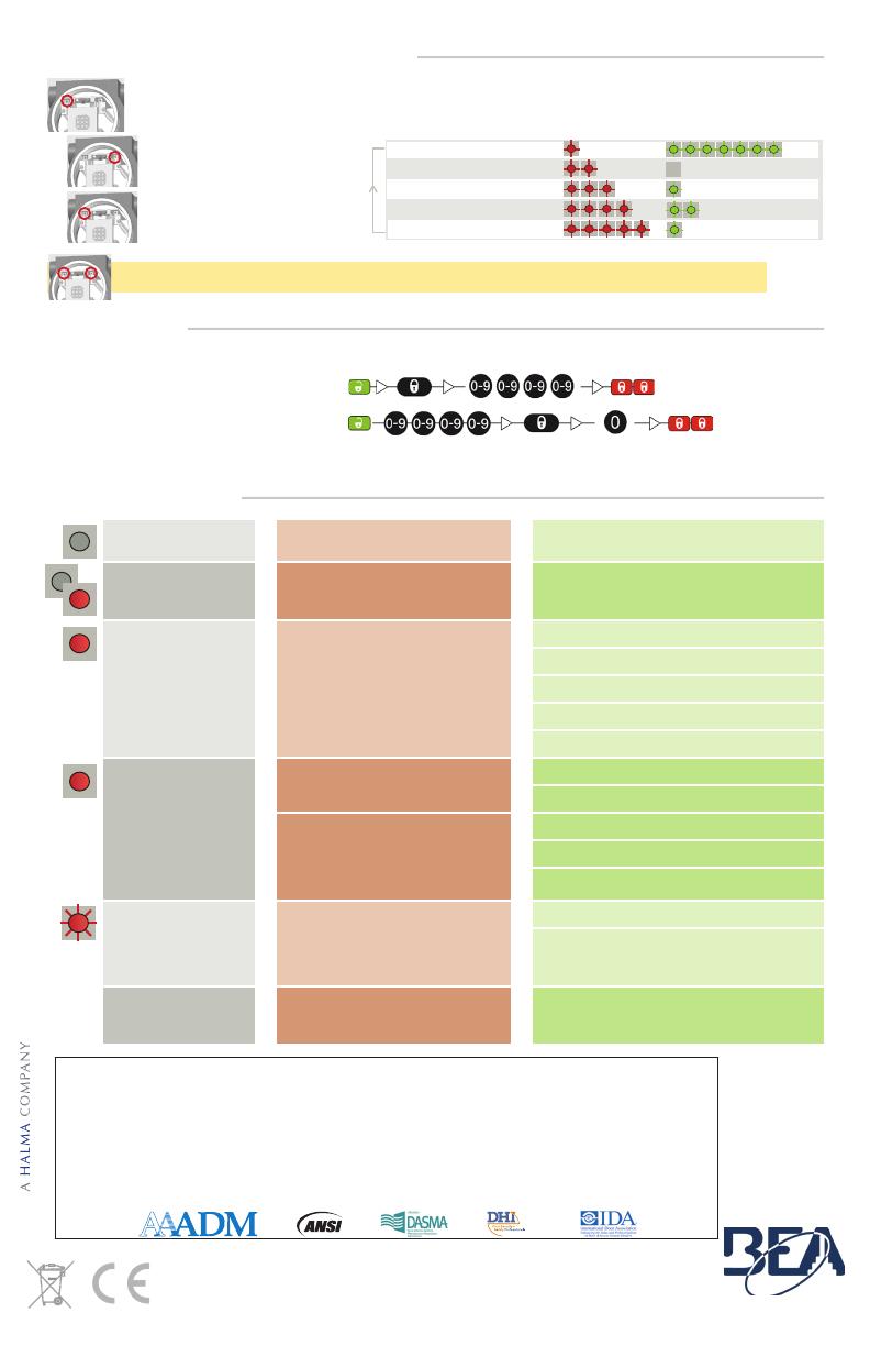
POSSIBLE SETTINGS BY PUSH BUTTONS
ACCESS CODE
TROUBLESHOOTING
Sensor appears
unresponsice
Sensor power is off. Check wiring and power supply.
Discrepancy between
sensor state and sensor
output
Improper output configuration on
sensor.
Change the output configuration setting on
each sensor connected to the door operator.
The sensor cycles in and
out of detection
The sensor is disturbed by vibration, a
moving object, or electrical noise from
nearby environment.
Ensure sensor is fixed properly.
Ensure detection mode is unidirectional.
Increase tilt angle.
Increase detection filter value.
Reduce field size.
Door opens for no
discernable reason
It rains and the sensor detects the
motion of the rain drops.
Ensure detection mode is unidirectional.
Increase detection filter value.
In highly reflective environments, the
sensor detects objects outside of its
detection field.
Change the antenna angle.
Reduce field size.
Increase detection filter value.
LED flashes quickly after
unlocking
Sensor needs access code to unlock. Enter correct access code.
If you forgot the code, cycle the power to access
the sensor without access code.
Change or delete the access code.
Sensor does not
respond to the remote
control
Batteries in the remote control are
weak or installed improperly.
Check batteries and change if necessary.
BEA, the sensor manufacturer, cannot be held responsible for incorrect installations or inappropriate adjustments of the sensor/device; therefore, BEA
does not guarantee any use of the sensor outside of its intended purpose.
BEA strongly recommends that installation and service technicians be AAADM-certifi ed for pedestrian doors, IDA-certifi ed for doors/gates, and factory-
trained for the type of door/gate system.
Installers and service personnel are responsible for executing a risk assessment following each installation/service performed, ensuring that the sensor
system installation is compliant with local, national, and international regulations, codes, and standards.
Once installation or service work is complete, a safety inspection of the door/gate shall be performed per the door/gate manufacturer recommendations
and/or per AAADM/ANSI/DASMA guidelines (where applicable) for best industry practices. Safety inspections must be performed during each service
call – examples of these safety inspections can be found on an AAADM safety information label (e.g. ANSI/DASMA 102, ANSI/DASMA 107, UL 325).
Verify that all appropriate industry signage and warning labels are in place.
BEA INSTALLATION/SERVICE COMPLIANCE EXPECTATIONS
PLEASE KEEP FOR FURTHER USE – DESIGNED FOR COLOR PRINTING
Tech Support: 1-800-407-4545 | Customer Service: 1-800-523-2462
General Tech Questions: T[email protected] | Tech Docs: www.BEAinc.com
©BEA | Original Instructions | 75.5863.03 PHOENIX EX 20180416
Only for EC countries: According the European Guideline 2012/19/EU for Waste Electrical and Electronic Equipment (WEEE)
(7)
(0)
(1)
(2)
(1)
TO START OR END AN ADJUSTMENT SESSION, press and hold either push button until the LED flashes or
stops flashing.
1 FIELD SIZE
Parameter number
2 HOLD-OPEN TIME
3 OUTPUT CONFIGURATION
4 DETECTION MODE
5 DETECTION FILTER
Value (factory values)
TO SCROLL THROUGH THE
PARAMETERS, press the right push
button.
TO CHANGE THE VALUE OF THE
CHOSEN PARAMETER, press the left
push button.
TO RESET TO FACTORY VALUES, press and hold both push buttons until both LEDs flash.
The access code (1 to 4 digits) is recommended to set sensors installed close to each other.
SAVING AN ACCESS CODE:
DELETING AN ACCESS CODE:
Once you have saved an access code, you always need to enter this code to unlock the sensor.
If you forget the access code, cycle the power. For the first minute, you can access the sensor without an access code.
  • Page 1 1
  • Page 2 2
  • Page 3 3
  • Page 4 4

BEA PHOENIX EX User guide

Type
User guide

BEA PHOENIX EX, the motion sensor with explosion-proof housing, provides reliable detection of moving objects in hazardous environments. With adjustable mounting height, detection zone, and sensitivity, it ensures optimal performance for various applications. The anti-tamper alert feature enhances security by notifying you of any unauthorized attempts to tamper with the sensor. Protect your assets and ensure safety with BEA PHOENIX EX.

Ask a question and I''ll find the answer in the document

Finding information in a document is now easier with AI