Page is loading ...

KEYSTONE MODEL WINN HISEAL HIGH PERFORMANCE BUTTERFLY VALVES
OperatiOn, installatiOn and maintenance instructiOns
1 STORAGE/SELECTION/PROTECTION
Storage
When valves are to be stored for some time
before being fitted, storage should be in
theoriginal delivery crates with any waterproof
lining and/or desiccant remaining in place.
Storage should be off the ground in a clean, dry
indoor area. If storage is for a period exceeding
six months the desiccant bags (if supplied)
should be changed at this interval.
Selection
Ensure that the materials of construction
and pressure/temperature limits shown on
thevalve identification label, are suitable for
the process fluid and conditions. If in doubt,
contact the factory.
Protection
Keystone Butterfly valves are delivered
with protection according to customer’s
specification, or in accordance with the Quality
Manual, to protect the valve seats and disc from
damage.
Wrapping and/or covers should be left in place
until immediately before fitting to the pipe.
2 INSTALLATION
1. Ensure that mating flanges and gaskets are
clean and undamaged.
2. Remove protective covers from valve faces.
3. With the valve in the closed position, fitinto
pipework tightening the flange bolts in a
diagonal pattern.
Refer to the following notes regarding
theindividual valve body type.
a. Wafer design
The wafer design is intended for
sandwiching between two pipe flanges
by means of through bolting. The body
incorporates locating holes or lugs to
enable the valve to be positioned centrally in
the pipeline thus ensuring the disc does not
foul when opening.
b. Lugged design
The lugged configuration facilitates
independent bolting of the valve to either
the upstream or downstream flanges and
is fully rated for end-of-line applications.
Before installation these instructions must be fully read and understood
Emerson.com/FinalControl VCIOM-01737-EN 18/02© 2017 Emerson. All Rights Reserved.
Centralization of the valve to the pipework
is more readily achieved than with the
wafer type, however care should be taken
to ensure that the disc does not foul the
mating flange or pipework when opening the
valve.
c. Double flange design
As Lugged design above.
NOTE
a. Keystone Winn HiSeal valves are bi-directional and
may be fitted either direction relative to the flow.
b. Installation may be carried out with shaft displaced
through any angle permitted by the bolting.
3 ROUTINE MAINTENANCE AND
OPERATIONAL SPARES
Routine maintenance
No routine maintenance is required other
than periodic inspection to ensure satisfactory
operation and sealing.
Any sign of leakage from the gland packing
should be addressed immediately by tightening
the gland nuts gradually and evenly. If no
further adjustment is possible the packing
should be renewed by following instructions in
paragraph 4.1.
Spare parts
Keystone valves are identified by a figure
number, which is stamped on the identification
plate, located on the valve body yoke. This
reference should be quoted in respect of any
after sales queries, spare parts or repair
enquiries/orders.
Two year operational spares
Soft Goods Kits only, are recommended for the
first two years of operation, as follows:
Soft-seated and Firesafe valves
• 1 Seat ring
• 2 Body gaskets
• 1 Set of gland packing
Metal-seated valves
• 1 Metal seat ring
• 2 Body gaskets
• 1 Set of gland packing
The number of kits required will
be recommended by our Technical
Sales department on request.
Other metallic components are not normally
replaced in theinitial 2 year period. Any
damage to metallic components such as
retaining ring, metal seat (seat energizer) or
disc may necessitate replacement of additional
components.
Consult Technical Sales department for advice.

2
KEYSTONE MODEL WINN HISEAL HIGH PERFORMANCE BUTTERFLY VALVES
OperatiOn, installatiOn and maintenance instructiOns
4 MAINTENANCE
CAUTION
Before attempting any maintenance, ensure
that the system has been depressurized and
ifnecessary, drained of any dangerous fluid.
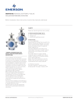
Parts identification
The illustrations on page 5 show the parts
comprising Firesafe and Soft Seated valves.
Either type is available with wafer, lugged or
double flanged body.
4.1 Replacement of gland packing
If further adjustment of the gland packing is
inappropriate, adopt the following procedure
for its removal and replacement.
1. Remove the operator (lever, gearbox or
actuator) in accordance with Instructions in
paragraph4.5.
2. a. Remove key from shaft.
b. Remove gland nuts (16).
c. Remove gland follower flange (14).
d. Remove gland follower (13).
e. Remove gland packing rings (12) using a
pointed instrument.
3. a. Fit new gland packing rings (12).
b. Refit gland follower (13).
c. Refit gland follower flange (14).
d. Refit gland nuts (16) tightening evenly
until heavy resistance is felt. During this
operation turn the stem to ensure that the
packing is not overtightened.
4. Refit the operator (see paragraph 4.5).
4.2 Replacement of valve seats
Firesafe and soft seated valves
1. Remove retaining ring (4) in accordance with
procedure described in paragraph 4.4.
2. a. Remove first body gasket (11).
b. Remove metal seal or energizer (5).
c. Remove second body gasket (11).
d. Remove PTFE seat (6).
If the seat is tight move the disc to the open
position and, if still tight, gently drive the
seat out of its housing from the back face of
the valve using a smooth blunt instrument.
3. Ensure that all components are clean.
Position the disc in the closed position.
4. Refit all components by reversing the steps
shown in (2) above.
NOTE
The body gaskets of lugged valves require holes for
cap screws pressing in on assembly.
Metal seat valves
Follow the above instructions, ignoring
reference to soft seats.
4.3 Replacement of shaft bearings
Removal
1. Remove operator in accordance with
theprocedure detailed in paragraph 4.5.
2. Remove the Gland Packing in accordance
with the procedure detailed in paragraph 4.1.
3. Remove the seat assembly, in accordance
with paragraph 4.2.
OR
Seat assembly may retain is situ to prevent
accidental damage.
4. With the disc in the fully open position and
its weight supported;
a. Drive out the disc retention pins
(spiral or taper)(7) using a punch.
b. Withdraw the shaft (3) from the body.
c. Remove the disc through the back face of
the valve body.
5. The bearings (9) / (10) are now exposed and
may be removed.
Refitting
1. Clean out bearing cavities and fit new
bearings.
2. Re-introduce the disc into the body in the
open attitude through the back face and
support its weight.
3. Refit the shaft ensuing that the shaft key-
way is on the same side as the disc Stop.
4. Refit the disc pins.
5. Reassemble gland assembly
(seeparagraph4.1).
6. Refit seat assembly (see paragraph 4.2).
7. Refit operator (see paragraph 4.5)

3
KEYSTONE MODEL WINN HISEAL HIGH PERFORMANCE BUTTERFLY VALVES
OperatiOn, installatiOn and maintenance instructiOns
4.4 Removal and refitting of retaining ring
Wafer body models
Removal
The retaining Ring is held in position by
theretaining ring spring.
1. Insert two pieces of bar into the tapped
holes in the retaining ring.
2. Rotate anti-clockwise and lift. The retaining
ring will wind out of the valve body recess
within two complete turns.
3. Assess the condition of the retaining ring
spring (8) and replace if necessary.
Refitting
1. Position the retaining ring spring (8) in the
recess of the retaining ring (4).
2. Place the retaining ring in the body recess
and, applying light pressure, turn the ring
clockwise.
3. The retaining ring will then wind into
position within two complete turns.
Lugged body models
The retaining ring is held in position by cap
screws (8) so that the ring is able to hold full
differential pressure in an end-of-line application.
Removal
1. Remove the cap screws (8) and lift out
retaining ring.
Refitting
1. Introduce the retaining ring into the body
recess and secure with cap screws (8).
4.5 Removal and refitting of operator
Lever removal
1. Release locking screw securing lever to
shaft.
2. Lift or prise the lever from the shaft, taking
care to retain the drive key.
3. Remove the lever stop plate by removing
thetwo securing screws.
Lever refitting
1. Secure lever stop plate to valve yoke by
means of two screws.
2. Fit thrust washer.
3. Position drive key in slot on shaft.
4. Fit lever to shaft and secure with locking
screw.
Lever adjustment
1. Hold the disc in the closed position
(0.25mm off the body stop).
2. Rotate the cam adjuster until it aligns
thestop plate with the lever.
3. Tighten the stop plate securing screws.
Gearbox removal – direct mounted type
1. Remove top cover of gearbox.
2. Remove securing bolts fixing gearbox to
valve yoke.
This may necessitate partial rotation of the
gearbox quadrant to expose the fasteners.
4.6 Setting of travel stops on gearbox
operators
a. With valve out of pipeline
1. Open valve
2. Wind off closed position stop
3. Close valve with 0.25 mm (0.010 ins)
feeler gauge under body/disc stop
4. Wind in closed position stop until
resistance is felt and lock in position
5. Open valve and fully close against
gearbox/actuator stop
6. Check gap under body stop and adjust if
necessary until 0.25 mm (0.010 ins) gap is
achieved
b. With valve in pipeline
1. Open valve
2. Wind off closed position stop
3. Carefully close valve until disc/stop is in
contact
4. Wind in closed position stop until
resistance is felt
5. Open valve
6. Wind in closed position stop a further
½-turn and lock in position
NOTE
For the setting of stops on Double acting pneumatic
actuators, with the air supply disconnected, methods
(a) and (b) can be applied.
WARNING
Not to be attempted with spring return units.
Body/disc
stop
Typical
closed
position
stop
Gearbox removal when mounted via an adaptor
plate
1. Remove bolting fixing gearbox to adaptor
plate (directly accessible).
Gearbox refitting
Reverse the above procedures
Actuator removal and refitting
Actuators are fitted via a mounting bracket and
are readily removed and refitted by directly
accessible bolting.

4
1
2
3
12
13
14
14
15
15
7
7
16
16
9
10
4
5
6
8
11
11
1
10
2
3
4
5
6
12
13
14
14
15
15
16
7
7
8
16
9
11
11
KEYSTONE MODEL WINN HISEAL HIGH PERFORMANCE BUTTERFLY VALVES
OperatiOn, installatiOn and maintenance instructiOns
PARTS LIST
Fire safe models
Item Description
1 Body
2 Disc
3 Shaft
4 Retaining ring
5 Metal seat
6 Soft seat
7 Disc pin
8 Retaining ring screw
9 Shaft bearing - top
10 Shaft bearing - bottom
11 Body gasket
12 Gland packing
13 Gland follower flange
14 Gland stud
15 Gland nut
16 Identification plate
Soft seated models as fire safe models, except
5 Seat energizer
8 Retaining ring spring
Fire safe model
Soft seated model
Neither Emerson, Emerson Automation Solutions, nor any of their affiliated entities assumes responsibility for the selection, use or maintenance of any product.
Responsibility for proper selection, use, and maintenance of any product remains solely with the purchaser and end user.
Keystone is a mark owned by one of the companies in the Emerson Automation Solutions business unit of Emerson Electric Co. Emerson Automation Solutions, Emerson
andthe Emerson logo are trademarks and service marks of Emerson Electric Co. All other marks are the property of their respective owners.
The contents of this publication are presented for informational purposes only, and while every effort has been made to ensure their accuracy, they are not to be
construed as warranties or guarantees, express or implied, regarding the products or services described herein or their use or applicability. All sales are governed by
our terms and conditions, which are available upon request. We reserve the right to modify or improve the designs or specifications of such products at any time without
notice.
Emerson.com/FinalControl
/