
Outdoor Lifestyles by Hearth & Home Technologies Inc. • Montana US-CAN • 4039-156 Rev K • 7/11
1
Owner’s Manual
Installation and Operation
Models:
Montana-36
Montana-42
Woodburning Fireplace
DO NOT DISCARD THIS MANUAL
CAUTION
• Important operating
a n d m a i n t e n a n c e
instructions included.
• Leave this manual with
party responsible for
use and operation.
• Read, understand
and foll o w th ese
instructions for safe
i n s t a l l a t i o n a n d
operation.
DO NOT
DISCARD
Installation and service of this replace should
be performed by quali ed personnel. Hearth
& Home Technologies suggests NFI certi ed
or factory-trained professionals, or technicians
supervised by an NFI certified
professional.
Fire Risk
• For use with solid wood fuel or decorative
gas appliance only.
• Do not install unvented gas logs.
WARNING
If the information in these instruc-
tions is not followed exactly, a
re may result causing property
damage, personal injury, or death.
• Do not store or use gasoline or other am-
mable vapors and liquids in the vicinity of
this or any other appliance.
• Do not over re. Over ring will void your
warranty.
• Comply with all minimum clearances to
combustibles as speci ed. Failure to
comply may cause house re.
WARNING
HOT SURFACES!
Glass and other surfaces are hot during
operation and cool down.
WARNING
• CAREFULLY SUPERVISE children in same room as
appliance.
• Alert ch ildre n and adu l t s to ha z ards of high
temperatures.
High temperatures may ignite clothing or other
ammable materials.
• Keep clothing, furniture, draperies and other combustibles
away.
Hot glass will cause burns.
• Do not touch glass until it is cooled
• NEVER allow children to touch glass
• Keep children away

Outdoor Lifestyles by Hearth & Home Technologies Inc. • Montana US-CAN • 4039-156 Rev K 7/11
2
Read this manual before installing or operating this replace.
Please retain this owner’s manual for future reference.
Congratulations on selecting a Outdoor Lifestyles wood
burning replace. The Outdoor Lifestyles replace you have
selected is designed to provide the utmost in safety, reliability
and efciency.
As the owner of a new replace, you’ll want to read and
carefully follow all of the instructions contained in this owner’s
manual. Pay special attention to all cautions and warnings.
This owner’s manual should be retained for future reference.
We suggest you keep it with your other important documents
and product manuals.
The information contained in this owner’s manual unless noted
otherwise, applies to all models and gas control systems.
Your new Outdoor Lifestyles wood burning replace will give
you years of durable use and trouble-free enjoyment. Welcome
to the Outdoor Lifestyles family of replace products!
Homeowner Reference Information
Model Name: Date purchased/installed:
Serial Number: Location on replace:
Dealership purchased from: Dealer phone:
Notes:
We recommend that you record the following pertinent
information about your replace:
Listing Label Information/Location
The model information regarding your specic replace can be found on the rating plate located on the smoke shield of the
replace.
Congratulations!
Grate
Serial Number
FIREPLACE NO.
MODEL NO.
MODEL NO.
MFG. DATE
WARNING: RISK OF
FIRE DAMAGE. REPLACE
GRATE WITH HEARTH & HOME
TECHNOLOGIES INC.
OUTDOOR FIREPLACE INTENDED FOR USE WITH HEARTH & HOME TECHNOLOGIES INC. LISTED FIREPLACE PARTS. SEE INSTALLATION AND
OPERATING INSTRUCTIONS FOR THIS MODEL. ONLY HEARTH & HOME TECHNOLOGIES INC. GLASS DOOR KITS CAN BE INSTALLED ON THIS UNIT.
FIREPLACE ALSO FOR USE
IN MANUFACTURED HOMES
YES
NO
CLEARANCE TO
COMBUSTIBLES:
CHIMNEY
2 IN. MIN.
FIREBOX
IN.
MIN.
FAN KIT
MODEL NO.
&
RATED AT
115 VOLTS, 50/60 Hz.,
AMP.
DO NOT OVERFIRE. USE ONLY: SOLID WOOD FUEL OR
LISTED DECORATIVE GAS APPLIANCE. DO NOT USE A
FIREPLACE INSERT OR OTHER PRODUCTS NOT
SPECIFIED FOR USE WITH THIS PRODUCT. IF DOORS
ARE USED OPERATE FIREPLACE WITH DOORS FULLY
OPEN OR CLOSED ONLY. WHEN BURNING A
DECORATIVE GAS APPLIANCE IN THE FIREPLACE,
ADJUST DAMPER TO THE FULLY OPEN POSITION.
WARNING! THIS FIREPLACE HAS NOT BEEN TESTED WITH AN UNVENTED
GAS LOG SET. TO REDUCE THE RISK OF FIRE OR INJURY, DO NOT
INSTALL AN UNVENTED GAS LOG SET INTO FIREPLACE.
WARNING! TO AVOID THE RISK OF DAMAGING FIREPLACE MATERIALS
AND INCREASING THE RISK OF SPREADING A FIRE DO NOT USE THE
FIREPLACE TO COOK OR WARM FOOD.
IF INSTALLATION OR OPERATING INSTRUCTIONS ARE MISSING
CONTACT: HEARTH & HOME TECHNOLOGIES INC.,
1915 W. SAUNDERS ST., MT. PLEASANT, IA 52641.
Fireplace
Model

Outdoor Lifestyles by Hearth & Home Technologies Inc. • Montana US-CAN • 4039-156 Rev K • 7/11
3
Table of Contents
1 Listing and Code Approvals
A. Appliance Certication . . . . . . . . . . . . . . . . . . . . . . . . . 4
2 Getting Started
A. Design and Installation Considerations . . . . . . . . . . . . 5
B. Typical Fireplace System. . . . . . . . . . . . . . . . . . . . . . . 5
C. Tools and Supplies Needed . . . . . . . . . . . . . . . . . . . . . 6
D. Inspect Fireplace and Components . . . . . . . . . . . . . . . 6
3 Framing and Clearances
A. Selecting Fireplace Location . . . . . . . . . . . . . . . . . . . . 7
B. Clearances . . . . . . . . . . . . . . . . . . . . . . . . . . . . . . . . . 9
C. Sidewalls/Surrounds . . . . . . . . . . . . . . . . . . . . . . . . . 10
D. Frame the Fireplace . . . . . . . . . . . . . . . . . . . . . . . . . 10
E. Chimney Requirements . . . . . . . . . . . . . . . . . . . . . . . 11
4 Installation of Fireplace
A. Install the Dual Cooling Air Kit . . . . . . . . . . . . . . . . . . 12
B. Secure the Fireplace . . . . . . . . . . . . . . . . . . . . . . . . . 13
5 Chimney Assembly
A. Chimney Requirements . . . . . . . . . . . . . . . . . . . . . . . 14
B. Using Offsets/Returns . . . . . . . . . . . . . . . . . . . . . . . . 15
C. Assemble the Chimney Sections . . . . . . . . . . . . . . . . 16
D. Install the Ceiling Firestops . . . . . . . . . . . . . . . . . . . . 16
E. Install the Attic Insulation Shield . . . . . . . . . . . . . . . . 17
F. Double-check the Chimney Assembly . . . . . . . . . . . . 17
G. Secure the Chimney . . . . . . . . . . . . . . . . . . . . . . . . . 17
6 Complete the Enclosure
A. Chimney Termination . . . . . . . . . . . . . . . . . . . . . . . . . 18
B. Chase Top . . . . . . . . . . . . . . . . . . . . . . . . . . . . . . . . . 19
C. Install the Termination Cap . . . . . . . . . . . . . . . . . . . . 20
7 Accessories
A. Gas Log/Lighter Provisions . . . . . . . . . . . . . . . . . . . . 22
8 Finishing
A. Hearth Extension . . . . . . . . . . . . . . . . . . . . . . . . . . . . 23
B. Finishing Material . . . . . . . . . . . . . . . . . . . . . . . . . . . 24
C. Mantel . . . . . . . . . . . . . . . . . . . . . . . . . . . . . . . . . . . . 24
D. Sidewalls/Surrounds . . . . . . . . . . . . . . . . . . . . . . . . . 24
E. Glass Doors . . . . . . . . . . . . . . . . . . . . . . . . . . . . . . . . 24
9 Operating Instructions
A. General Information . . . . . . . . . . . . . . . . . . . . . . . . . . 25
B. Outside Air . . . . . . . . . . . . . . . . . . . . . . . . . . . . . . . . . 26
C. Clear Space Near the Fireplace . . . . . . . . . . . . . . . . 26
D. Flue Damper . . . . . . . . . . . . . . . . . . . . . . . . . . . . . . . 26
E. Firescreen . . . . . . . . . . . . . . . . . . . . . . . . . . . . . . . . . 26
F. Glass Doors . . . . . . . . . . . . . . . . . . . . . . . . . . . . . . . . 26
G. Grate . . . . . . . . . . . . . . . . . . . . . . . . . . . . . . . . . . . . . 27
H. Wood Fuel . . . . . . . . . . . . . . . . . . . . . . . . . . . . . . . . . 27
I. Starting a Fire . . . . . . . . . . . . . . . . . . . . . . . . . . . . . . 28
10 Troubleshooting
Diagnostics and Problem Solving. . . . . . . . . . . . . . . . . . . 29
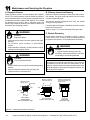
11 Maintenance and Servicing the Fireplace
A. Disposal of Ashes . . . . . . . . . . . . . . . . . . . . . . . . . . . 30
B. Chimney Inspection/Cleaning . . . . . . . . . . . . . . . . . . 30
C. Firebox Refractory . . . . . . . . . . . . . . . . . . . . . . . . . . . 30
D. Maintenance Task List . . . . . . . . . . . . . . . . . . . . . . . . 31
E. Chimney Fire . . . . . . . . . . . . . . . . . . . . . . . . . . . . . . . 31
12 Reference Materials
A. Fireplace Dimensions . . . . . . . . . . . . . . . . . . . . . . . . 32
B. Fireplace Components . . . . . . . . . . . . . . . . . . . . . . . 33
C. Chimney Components . . . . . . . . . . . . . . . . . . . . . . . . 34
D. Service Parts . . . . . . . . . . . . . . . . . . . . . . . . . . . . . . . 38
E. Limited Warranty . . . . . . . . . . . . . . . . . . . . . . . . . . . . 42
F. Contact Information . . . . . . . . . . . . . . . . . . . . . . . . . . 44
Note: An arrow () found in the text signies change in content.

Outdoor Lifestyles by Hearth & Home Technologies Inc. • Montana US-CAN • 4039-156 Rev K 7/11
4
1
Listing and Code Approvals
A. Appliance Certication
This replace system has been tested and listed in accor-
dance with UL 127 and CAN/ULC-S610-M87 standards by
Underwriters Laboratories Inc. for installation and operation
in the United States and Canada..
This replace has been tested and listed for use with the op-
tional components specied in this manual. These optional
components may be purchased separately and installed at
a later date.
Installation of a dual cooling air kit is required and must be
installed at the time of the initial replace installation. Failure
to do so may result in a re causing property damage and/
or personal injury.
Outdoor Lifestyles is a registered trademark of Hearth &
Home Technologies Inc.
Not intended for use as a primary heat source.
This replace is tested and approved as a decorative
replace. It should not be factored as a primary heat
source in residential heating calculations.
Improper installation, adjustment, alteration, service
or maintenance can cause injury or property damage.
Refer to the owner’s information manual provided with
this replace. For assistance or additional information
consult a qualied installer, service agency or your
dealer.
WARNING
Fire Risk
• Do not install or operate damaged replace.
• Do not modify replace.
• Installation other than as instructed by Hearth & Home
Technologies Inc. is strictly prohibited.
• Do not operate the replace without fully assembling
all components.
• Do not overre.
• Do not install an unvented gas log set. This replace
has not been tested for use with unvented gas log
sets.
• Installation and/or use of any component part not
approved by Hearth & Home Technologies.
Hearth & Home Technologies disclaims any responsibility
for, and the warranty and agency listing will be voided by
the above actions.
WARNING
Fire Risk
WARNING
WARNING! TO AVOID THE RISK OF DAMAGING FIRE-
PLACE MATERIALS AND INCREASING THE RISK OF
SPREADING A FIRE, DO NOT USE THE FIREPLACE TO
COOK OR WARM FOOD.

Outdoor Lifestyles by Hearth & Home Technologies Inc. • Montana US-CAN • 4039-156 Rev K • 7/11
5
2
Getting Started
A. Design and Installation Considerations
Draft is the pressure difference needed to vent replaces
successfully. Considerations for successful draft include:
• Location of replace and chimney
Check building codes prior to installation.
• Installation MUST comply with local, regional,
state and national codes and regulations.
• Consult insurance carrier, local building inspector,
re ofcials or authorities having jurisdiction about
restrictions, installation inspection, and permits.
CAUTION
When planning a replace installation, it is necessary to de-
termine the following information before installing:
• Where the fireplace is to be installed. See Sections
3 and 4.
• The vent system conguration to be used. See Sections
5 and 6.
• Framing and nishing details. See Sections 3, 6 and 8.
• Whether optional accessories are desired. See
Section 12.
Moisture Resistance:
This outdoor replace will shed moderate amounts of water,
but is not waterproof. Water and condensing water vapor
may enter the chase under certain conditions.
The replace will not perform as an exterior wall. Moisture
penetration must be considered for construction that places
the replace in structure walls or on moisture sensitive sur-
faces.
When installed on exterior walls: Hearth & Home Tech-
nologies recommends that the replace chase be con-
structed outside the structure’s weather envelope. Where
the platform meets the wall, use a ashing detail similar to
that required for attached decks. Chase platforms, including
hearths should slope away from the structure at 1/8 in. to
1/4 in. per foot. The replace can be shimmed level.
When installed on surfaces where water may collect or
cause damage: Hearth & Home Technologies recommends
that a drainage pan be placed under the unit. This can be
constructed of metal, adhesive polymer membrane (such as
ice and water shield) or other suitable materials. A means of
drainage out of the pan such as tubes or weep holes should
be provided. A slope of 1/8 in. to 1/4 in. per foot towards
the drain port is suggested. The replace can be shimmed
level.
Hearths should slope away from the front of the replace
and chase at 1/8 in. to 1/4 in. per foot. Spark strips must be
on top of any combustible hearth materials used for moisture
management.
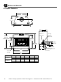
B. Typical Fireplace System
The Outdoor Lifestyle replace system consists of the fol-
lowing:
• Fireplace/integral grate/dual cooling air system
• Refractory
• Chimney termination cap
• Chimney system (SL1100 series pipe is NOT approved
for Canada)
• Hearth extension
Optional components include:
• Glass doors
• Weather cover
• SLA10 11-10 in./279-254 mm Adapter (required in
Canada)
Termination Cap
Chimney System
Refractory
Integral Grate
Hearth Extension
SLA10 not shown
Figure 2.1 Typical Fireplace System

Outdoor Lifestyles by Hearth & Home Technologies Inc. • Montana US-CAN • 4039-156 Rev K 7/11
6
Before beginning the installation be sure the following tools
and building supplies are available:
Reciprocating saw Framing material
Pliers High temp caulking material
Hammer Gloves
Phillips screwdriver Framing square
Flat blade screwdriver Electric drill and bits
Plumb line Safety glasses
Level Tape measure
1/2-3/4 in. length, #6 or #8 self-drilling screws
Misc. screws and nails
• Keep replace dry.
• Mold or rust may cause odors.
CAUTION
D. Inspect Fireplace and Components
• Carefully remove the replace and components from the
packaging.
• The vent system components and doors are shipped in
separate packages.
• Report to your dealer any parts damaged in shipment.
• Read all the instructions before starting the installation.
Follow these instructions carefully during the
installation to ensure maximum safety and benet.
Fire Risk
Explosion Risk
Inspect fireplace and components for
damage. Damaged parts may impair safe
operation.
• Do NOT install damaged components.
• Do NOT install incomplete components.
• Do NOT install substitute components
Report damaged parts to dealer.
WARNING
C. Tools and Supplies Needed

Outdoor Lifestyles by Hearth & Home Technologies Inc. • Montana US-CAN • 4039-156 Rev K • 7/11
7
3
Framing and Clearances
A. Selecting Fireplace Location
This outdoor replace will shed moderate amounts of water,
but is not waterproof. Water and condensing water vapor
may enter the chase under certain conditions.
The replace will not perform as an exterior wall. Moisture
penetration must be considered for construction that places
the replace against structure walls or on moisture sensitive
surfaces.
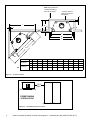
• Exterior Walls (see Figure 3.1)
Hearth & Home Technologies recommends that the
replace chase be constructed outside the structure’s
weather envelope. Where the platform meets the wall, use
a ashing detail similar to that required for attached decks.
Chase platforms, including hearths, should slope away
from the structure at 1/8 in to 1/4 in. per foot. The replace
can be shimmed level. Build the outside enclosure out of
standard building materials, being careful to maintain the
minimum air clearances specied in these installation
instructions.
Fire Risk
Provide adequate clearances.
• Around air openings
• To combustibles
• For service access.
Locate replace away from trafc areas.
WARNING
Note:
• Illustrations and photos reect typical installations
and are FOR DESIGN PURPOSES ONLY.
• Illustrations/diagrams are not drawn to scale.
• Actual installation/appearance may vary due to
individual design preference.
• Hearth & Home Technologies reserves the right to
alter its products.
• Freestanding Installations (see Figure 3.2)
When installing this replace as a freestanding replace
on your porch, patio or in your yard, it must be enclosed
to prevent impact damage to the replace. The exterior
of the enclosure may be nished in a textured plywood,
a wood clapboard siding, brick, or a cultured stone. Vinyl
siding is not recommended for use on the front of the
replace due to the heat the replace produces. This can
cause the vinyl siding to deteriorate.
• When Installed on Surfaces Where Water May Collect
or Cause Damage:
Hearth & Home Technologies recommends that a drainage
pan be placed under the unit. This can be constructed
of metal, adhesive polymer membrane (such as ice
and water shield) or other suitable materials. A means
of drainage out of the pan such as tubes or weep holes
should be provided. A slope of 1/8 in. to 1/4 in. per foot
towards the drain port is suggested. The replace can be
shimmed level.
Hearths should slope away from the front of the replace
and chase at 1/8 in. to 1/4 in. per foot. Spark strips must
be used on top of any combustible hearth materials used
for moisture management.

Outdoor Lifestyles by Hearth & Home Technologies Inc. • Montana US-CAN • 4039-156 Rev K 7/11
8
B
A
H
F
Note: If this surface is
inside the building’s
warm air envelope...
...then this surface
must be an exterior
wall system.
C
D
G
G
C
D
H
G
F
J
I
E
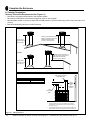
Figure 3.1 Fireplace Locations
FREESTANDING
INSTALLATION
(Combustible Structure)
(Enclosed Fireplace)
10 ft
Min.
Figure 3.2 Freestanding Fireplace Locations
Model A B C D E F G H I J
Montana-36
in. 24-1/2 24 42 43 46 1/2 1-1/2 1-1/2 74-1/2 53-1/2
mm 622 610 1067 1092 1168 13 38 38 1892 1359
Montana-42
in. 24-1/2 24 48 49 52 1/2 1-1/2 1-1/2 80-1/2 57
mm 622 610 1219 1245 1321 13 38 38 2045 1448

Outdoor Lifestyles by Hearth & Home Technologies Inc. • Montana US-CAN • 4039-156 Rev K • 7/11
9
0 in.
0 in. to level
of standoffs
Combustible Object
36 in.
(914 mm)
1-1/2 in. (38 mm)
Drywall
0 in.
1/2 in. (13 mm)
1-1/2 in.
(38 mm)
B. Clearances
Figure 3.3 Clearances to Combustible Materials
Fire Risk
• Comply with all minimum clearances to combustibles as speci ed.
• Framing or nishing material used on the front of, or in front of, the
appliance closer than the minimums listed, must be constructed entirely
of noncombustible materials (i.e., steel studs, concrete board, etc.).
Failure to comply may cause re.
WARNING

Outdoor Lifestyles by Hearth & Home Technologies Inc. • Montana US-CAN • 4039-156 Rev K 7/11
10
2 in./51 mm
minimum air
space clearance
to the enclosure.
Use only noncombustible
material below the top of
the top standoffs.
28-3/8 in.
721 cm
74-1/2 in.
1892 cm
53- 7/8 in.
1368 cm
C. Sidewalls/Surrounds
Adjacent combustible side walls must be located a minimum of 12 in. (305 mm) from the replace opening. See Figure 3.4.
If you are using a decorative surround constructed of combustible material, it must be located within the shaded area de-
ned in Figure 3.3. Short stub walls are also acceptable if they are contained within the shaded area.
D. Frame the Fireplace
Figure 3.5 shows a typical framing (using 2 x 4 lumber) of the replace, assuming combustible materials are used. All re-
quired clearances to combustibles around the replace must be adhered to. See Figure 3.2. Any framing across the top of
the replace must be above the level of the top standoffs.
14-3/8 in./36.5 cm
12 in.
30.5 cm
39
deg.
4 in./10.2 cm
BRICK
FRONT
FLUSH FRONT
12 in.
30.5 cm
9-3/4 in./24.8 cm
50
deg.
A
B
Cat # A B
MONTANA-36 & 36H 36 in./91.4 cm 42 in./106.7 cm
MONTANA-42 & 42H 42 in./106.7 cm 48 in./121.9 cm
Figure 3.4 Sidewalls and Surrounds
Figure 3.5 Framing the Fireplace

Outdoor Lifestyles by Hearth & Home Technologies Inc. • Montana US-CAN • 4039-156 Rev K • 7/11
11
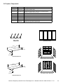
E. Chimney Requirements
When planning your replace location, the chimney construc-
tion and necessary clearances must be considered. The re-
place system and chimney components have been tested to
provide exibility in construction. The following gures are
the minimum distances from the base of the replace.
• Minimum overall straight height is 6 ft 4 in. if the replace
is freestanding and a minimum of 10 ft from a combustible
structure. See Figure 3.2.
• Chimney must extend 2 ft (.6 m) above any portion
of the roof within 10 ft (3 m) of the chimney. Refer to
Figure 6.1.
Note: A maximum of two pairs of offsets and returns may
be used.
ft m
• Minimum heightwith offset/return 16 4.88
• Maximum height 90 27.43
• Maximum chimney length between an offset
and return
20 6.1
• Maximum distance between chimney
stabilizers
35 10.67
• Double offset/return minimum height 24 7.32
• Maximum unsupported chimney length
between the offset and return
6 1.83
• Maximum unsupported chimney height above
the replace
35 10.67
• Minimum overall straight height if replace is
freestanding
6.33 1.93

Outdoor Lifestyles by Hearth & Home Technologies Inc. • Montana US-CAN • 4039-156 Rev K 7/11
12
72 in./183 cm
min.
TR11/TR444
Termination
Cap
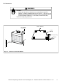
A. Install the Dual Cooling Air Kit
The cooling air kit is supplied as a standard feature with this
replace and is required for safe operation. Installation must
be done at the time of initial construction. The cooling air in-
let tubes must be a minimum of 72 in. (1829 mm) above the
base of the replace to prevent potential blockage by snow
or yard debris. See Figure 4.1.
To install the air kit collar, slide one of the tabs down into the
seam. See Figure 4.2. Secure the collar tabs to the replace
with screws placed into the holes provided. See Figure 4.3.
Repeat for other side.
Sharp Edges
• Wear protective gloves and safety glasses
during installation.
CAUTION
4
Installation of Fireplace
Fire Risk
Asphyxiation Risk
Do not draw outside combustion air from:
• Wall, oor or ceiling cavity.
• Enclosed space such as an attic or
garage.
• Close proximity to exhaust vents or
chimneys.
Fumes or odor may result.
WARNING
Figure 4.1 Cooling Air Location
Figure 4.2 Slide the Tabs
Figure 4.3 Secure the Tabs
Note: The cooling air kit must terminate at least 6 ft. (1.83 m)
above ground level.
11-10 in./279-254 mm
adapter not shown

Outdoor Lifestyles by Hearth & Home Technologies Inc. • Montana US-CAN • 4039-156 Rev K • 7/11
13
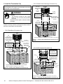
B. Secure the Fireplace
• Position the Fireplace
This replace may be placed on either a combustible or
noncombustible continuous at surface. Follow the in-
structions for framing in Section 3.D. Slide the replace
into position. Be sure to provide the minimum air clear-
ance at the sides and back of the replace assembly.
See Section 3.B.
Included with your replace you will nd two metal
hearth strips measuring approximately 26 in. x 4 in.
(660 mm x 102 mm). These strips are used to provide
added protection where the replace and the hearth ex-
tension meet.
Slide each metal strip 2 in. (51 mm) under the front
edge of the replace. The individual pieces must over-
lap each other by 1 in. (25 mm) minimum in the middle
of the replace to provide continuous coverage of the
oor. See Figure 4.4. These metal strips should extend
from the front and sides of the replace opening by 2 in.
(51 mm).
Note: When elevating the fireplace above the hearth
extension the front of the elevated platform must be
protected with a protective metal hearth strip as shown in
Figure 4.6.
Raised Platform
Floor
2 in.
(51 mm)
1 in. (25 mm) min.
overlap
2 in.
(51 mm)
Top piece must overlap
bottom piece
Figure 4.5 Protect the Front of an Elevated Platform
• Level the Fireplace
Level the replace side-to-side and front-to-back. Shim
with noncombustible material, such as sheet metal, as
necessary. Secure the replace (using the nailing ang-
es located on either side of the replace) to the vertical
framing.
Important: To ensure proper t of the glass doors, check
the fireplace opening for square. Measure diagonal
distances of the opening to make sure they are equal.
If they are not, continue to shim the replace until those
diagonals are equal.
Protective metal strips are placed 2 in. (51 mm) under the
front of the fireplace and must extend beyond the front
and sides of fireplace opening by 2 in. (51 mm).
1 in. (25 mm)
overlap
Figure 4.4 Position the Protective Metal Hearth Strips
• Place the Protective Metal Hearth Strips
Fire Risk!
• Prevent contact with sagging, loose
insulation.
• Do NOT install against vapor barriers or
exposed insulation.
WARNING
Fire Risk!
• Metal hearth strips MUST be installed.
Sparks or embers may ignite ooring.
WARNING

Outdoor Lifestyles by Hearth & Home Technologies Inc. • Montana US-CAN • 4039-156 Rev K 7/11
14
A. Chimney Requirements
Vertical distances are measured from the base of the re-
place.
• Minimum overall straight height is 6 ft 4 in. if the replace
is freestanding and a minimum of 10 ft from a combustible
structure. See Figure 3.2.
• Chimney must extend 2 ft (.6 m) above any portion
of the roof within 10 ft (3 m) of the chimney. Refer to
Figure 6.1.
To determine the chimney components needed to complete
your particular installation, follow the steps below:
• Determine the total vertical height of the fireplace
installation. This dimension is measured from the base of
the replace assembly to the point where the smoke exits
the termination cap.
• Subtract the effective height of the replace assembly from
the overall height of the replace installation (measured
from the base of the fireplace to the bottom of the
termination cap).
• Refer to Table 5.1 to determine what components must
be selected to complete the replace installation.
• Determine the number of ceiling restops, stabilizers,
roof flashing, etc. required to complete the fireplace
installation.
Table 5.1
• Do NOT connect this fireplace to a chimney flue
servicing another appliance.
• Do NOT connect to any air distribution duct or
system.
CAUTION
Fire Risk
• Must maintain 2 in. (51 mm) air clearance
to insulation and other combustible
materials.
WARNING
Note: A maximum of two pairs of offsets and returns may
be used.
5
Chimney Assembly
ft m
• Minimum heightwith offset/return 16 4.88
• Maximum height 90 27.43
• Maximum chimney length between an offset
and return
20 6.1
• Maximum distance between chimney
stabilizers
35 10.67
• Double offset/return minimum height 24 7.32
• Maximum unsupported chimney length
between the offset and return
6 1.83
• Maximum unsupported chimney height above
the replace
35 10.67
• Minimum overall straight height if replace is
freestanding
6.33 1.93
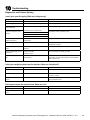
HEIGHT OF CHIMNEY COMPONENTS in. mm
US Canada ONLY
Chimney Stabilizer
SL11 SL4 4-3/4 121
Ceiling Firestops
FS538 FS538 0 0
FS540 FS540 0 0
Offsets/Returns
SL1130 SL430 14-1/2 368
Chimney Sections*
SL1106 SL406 4-3/4 121
SL1112 SL412 10-3/4 273
SL1118 SL418 16-3/4 425
SL1136 SL436 34-3/4 883
SL1148 SL448 46-3/4 1187
n/a SLA10 16-3/4 425
* Dimensions reect effective height.

Outdoor Lifestyles by Hearth & Home Technologies Inc. • Montana US-CAN • 4039-156 Rev K • 7/11
15
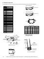
B. Using Offsets/Returns
To bypass any overhead obstructions, the chimney may be
offset using an offset/return.
An offset and return may be attached together or a chimney
section(s) may be used between an offset and return.
Perform the following steps to determine the correct chim-
ney component combination for your particular installation:
• Measure how far the chimney needs to be shifted to enable
it to avoid the overhead obstacle. See Figure 5.1. Use
dimension “A” to determine chimney section required to
achieve the needed shift.
• After determining the offset dimension, refer to Table 5.2
and nd the “A” dimension closest to but not less than the
distance of shift needed for your installation.
• The “B” dimension that coincides with the “A” dimension
represents the required vertical clearance that is needed
to complete the offset and return.
• Read across the chart and nd the number of chimney
sections required and the model number of those particular
chimney parts.
• Whenever the chimney penetrates a oor/ceiling, a ceiling
restop must be installed.
• The effective height of the replace assembly is measured
from the base of the replace to the top of the starter collar.
See Dimensions in Section 12.
Table 5.2
A
B
1-1/4 in. (32 mm)
OVERLAP
Figure 5.1 Chimney Offset/Return
Example: Your “A” dimension from Figure 5.3 is
14 1/2 in. (368 mm). Using Table 5.2 the dimension
closest to, but not less than 14 1/2 in. (368 mm) is
15 3/4 in. (400 mm) using a 30° offset/return. It is
then determined from the table that you would need
36 5/8 in. (930 mm) (Dimension “B”) between the
offset and return. The chimney components that best
t your application are two SL1112s or SL412s.
Fire Risk
• Draft will be restricted if offsets/returns
greater than 30° are used.
WARNING
A B
SL1106
SL406
SL1112
SL412
SL1118
SL418
SL1136
SL436
SL1148
SL448in. mm in. mm
4 7/8 124 17 7/8 454 - - - - -
7 1/4 184 2 2 559 1 - - - -
9 3/4 248 26 1/8 664 2 - - - -
10 1/4 260 27 1/4 692 - 1 - - -
12 3/4 324 31 3/8 797 1 1 - - -
13 1/4 337 32 3/8 822 - - 1 - -
15 3/4 400 36 5/8 930 - 2 - - -
18 1/8 460 40 3/4 1035 1 2 - - -
18 3/4 476 41 3/4 1060 - 1 1 - -
21 3/4 552 47 1194 - - 2 - -
22 1/4 565 48 1219 - - - 1 -
24 3/4 629 52 1/8 1324 1 - - 1 -
27 3/4 705 57 3/8 1457 - 1 - 1 -
28 1/4 718 58 3/8 1483 - - - - 1
30 3/4 781 62 1/2 1588 1 - - - 1
33 3/4 857 67 3/4 1721 - 1 - - 1
36 3/4 933 73 1854 - - 1 - 1
39 3/4 1010 78 1/8 1984 - - - 2 -
41 1/8 1045 82 3/8 2092 1 - - 2 -
45 3/4 1162 88 1/2 2248 - - - 1 1
48 1/8 1222 92 3/4 2356 1 - - 1 1
51 3/4 1314 98 7/8 2511 - - - - 2
Proper assembly of air cooled chimney parts results in an overlap of chimney joints
of 1-1/4 in. (32 mm). Effective length is built into this table.

Outdoor Lifestyles by Hearth & Home Technologies Inc. • Montana US-CAN • 4039-156 Rev K 7/11
16
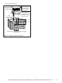
C. Assemble the Chimney Sections
Attach either a straight chimney section or an offset to the
top of the replace (depending on your installation require-
ment). Chimney sections are locked together by pushing
downward until the top section meets the stop bead on the
lower section.
The inner ue is placed to the inside of the ue section below
it. The outer casing is placed outside the outer casing of the
chimney section below it. See Figure 5.2.
D. Install the Ceiling Firestops
• Mark and cut an opening in the ceiling for the ceiling
restop being used. See Figure 5.3.
• Frame the opening with the same size lumber used in the
ceiling joists.
• Install the ceiling restop.
Note: The ceiling restop MUST be nailed to the bottom
of the ceiling joists EXCEPT when the space above is
uninsulated and the attic insulation shield is not being used
(see Figure 5.5). When the attic insulation shield is used
the ceiling restop may be above or below the joist of an
insulated ceiling.
Note: You must provide support for the pipe during
construction and check to be sure inadvertent loading has
not dislodged the chimney section from the replace or at
any chimney joint.
Note: Inner flue and outer liner sections cannot be
disassembled once locked together. Plan ahead to ensure
the proper installation height is achieved with the selected
chimney components.
• Ceiling restops must be used at ceiling/oor.
• Chase construction requires ceiling restops at each
oor or every 10 ft ( 3.05 m) of clear space.
• Use same dimensional lumber as joists.
Ceiling restop slows spread of re and reduces cold air
inltration.
CAUTION
Figure 5.2 Assembling Chimney Sections
Fire Risk
Do NOT install substitute or damaged
chimney components.
• MUST use chimney system described in
this manual.
• NO OTHER chimney components may
be used.
Substitute or damaged chimney components
may impair safe operation.
WARNING
ROOM ABOVE (non-insulated ceiling)
ATTIC ABOVE (insulated ceiling)
B
A
Ceilng firestop from
bottom
Ceiling firestop from
top
Note: Use same dimensional lumber for framing
ceiling firestop and joists.
Figure 5.3 Installing the Ceiling Firestop
Catalog #
A B
in. mm in. mm
FS538 17 432 17 432
FS540 17 432 26 660

Outdoor Lifestyles by Hearth & Home Technologies Inc. • Montana US-CAN • 4039-156 Rev K • 7/11
17
E. Install the Attic Insulation Shield
An insulation shield must be installed when there is a pos-
sibility of insulation coming into contact with the factory built
chimney system.
• Bend the tabs at the top of the attic insulation shield inward.
This will help keep the chimney section centered in the
shield.
• Position the shield over the vertical chimney section where
it penetrates a ceiling restop.
• Slide the shield down until it rests on the ceiling restop.
The ceiling restop will support the insulation shield. See
Figures 5.4 and 5.5.
F. Double-check the Chimney Assembly
Continue assembling the chimney sections up through the
ceiling restops as needed. While doing so, be aware of the
height and unsupported chimney length limitations given un-
der Section 5.A. Chimney Requirements.
Check each section by pulling up slightly from the top to en-
sure proper engagement before installing the succeeding
sections. If they have been connected correctly, they will not
disengage when tested.
G. Secure the Chimney
When offsets and returns are joined to straight pipe sections,
they must be locked into position with the screws provided*
(outer only), using the predrilled holes. To prevent gravity
from pulling the chimney sections apart, the returns and the
chimney stabilizers have hanger straps for securing these
parts to joists or rafters. See Figure 5.6.
* or equivalent #6 or #8 sheet metal screw no longer than
3/4 in. (19 mm).
24 in.
(610 mm)
Attic
Insulation
Shield
Chimney
Insulation
13 in.
(330 mm)
17 in.
(423 mm)
Ceiling Firestop
Tabs
Figure 5.4 Install Attic Insulation Shield Above the Ceiling
Attic
Insulation
Shield
Chimney
Insulation
Ceiling Firestop
Tabs
24 in.
(610 mm)
13 in.
(330 mm)
17 in.
(423 mm)
Figure 5.5 Install Attic Insulation Shield Below the Ceiling
Ceiling
Firestop
Straps
Optional
Additional
Support
Joint
Band
(Optional)
Figure 5.6 Secure the Chimney
Fire Risk
• DO NOT pack insulation or other
combustibles: between ceiling restops;
between chimney and attic insulation
shield.
• ALWAYS maintain specied clearances
around chimney and ceiling restops.
• Install ceiling restops as specied.
Failure to keep insulation or other material
away from chimney pipe may cause re.
WARNING
Fire Risk
• Secure offsets with screws (not to exceed
3/4 in./19 mm in length).
WARNING
• Secure returns with strapping.
• Straight chimney sections may be secured with screws
(not to exceed 3/4 in./19 mm in length) at the joints.
Keep chimney sections from separating or twisting.

Outdoor Lifestyles by Hearth & Home Technologies Inc. • Montana US-CAN • 4039-156 Rev K 7/11
18
6
Complete the Enclosure
Figure 6.1 Multiple Chimneys
A. Chimney Termination
Chimney Termination Requirements (See Figure 6.1)
• Must have a cap approved and listed for this replace system
• Must not be located where it will become plugged by snow or other material
• Must terminate at least 3 ft (914 mm) above the roof and at least 2 ft (610 mm) above any portion of the roof within 10 ft
(3.05 m)
• Must be located away from trees or other structures
Slanted Roofs
Flat Roofs
Chimney must
extend 3 ft (.9 m)
above the roof
Chimney must extend 2 ft (.6 m)
above any portion of the roof or
adjacent structures within
10 ft (3 m) of the chimney
Chimney must
extend 3 ft (.9 m)
above the roof
Chimney must extend 2 ft (.6 m)
above any portion of the roof or
adjacent structures within
10 ft (3 m) of the chimney
Multiple Chimney Locations
A B
6 in. (minimum) up to 20 in.
152 mm/508 mm
18 in. minimum
457 mm
20 in. and over 0 in. minimum
Gas, Wood or Fuel Oil
Termination Cap
Wood
Minimum
(See
illustration
above)
B
Gas
Termination
Cap **
A *
Perpendicular Wall
*
If using decorative cap cover(s), this distance may need to be
increased. Refer to the installation instructions supplied with the
decorative cap cover.
**
In a staggered installation with both gas and wood terminations, the
wood termination cap must be higher than the gas termination cap.

Outdoor Lifestyles by Hearth & Home Technologies Inc. • Montana US-CAN • 4039-156 Rev K • 7/11
19
Termination Cap
Storm Collar
Slope Downward
Turn-down
Drip Edge
Chase
(Chimney)
2 in. (51 mm) Collar
on Chase Top
Caulk
.018 (26 ga) min.
Galvanized
Chase Top
Figure 6.3 Chase Top Construction
B. Chase Top
A metal chase top is required to seal the top of the chase
around the chimney pipe. The top should include a turn-
down and drip edge to prevent water from seeping into the
chase. Provide a 1/8 in. (3 mm) gap around the ue pipe
and slope the top downward away from the penetration. See
Figure 6.3.
• All seams must be caulked to prevent leaks.
• A chase installation must use a chase top. Chase tops
are available from your Hearth & Home dealer or may be
eld constructed.
• Attach the chase top to the top of the chase.
Figure 6.2 Ceiling/Attic Construction
Fire Risk
• Must maintain 2 in. (51 mm) air clearance
to insulation and other combustible
materials.
WARNING
Mark the Exit Point of the Roof
Locate the point where the chimney will exit the roof by plumbing down to the
center of the chimney. Drive a nail up through the roof to mark the center. See
Figure 6.2.
Cut Out the Hole in the Roof
Measure to either side of the nail and mark the 14-1/2 in. x 14-1/2 in.
(368 mm x 368 mm) opening required. This is measured on the horizontal;
actual length may be larger depending on the pitch of the roof. Cut out and
frame the opening. See Chapter 25 of the Uniform Building Code for roof
framing details.
Assemble the Chimney Sections Through the Roof
Continue to add chimney sections through the roof opening, maintaining at
least a 2 in. (51 mm) air space to combustible materials.
Install the Roof Flashing
If a roof ashing is to be used, install the roof ashing appropriate to the
roof pitch and install a round termination cap and storm collar following the
instructions shipped with the cap.

Outdoor Lifestyles by Hearth & Home Technologies Inc. • Montana US-CAN • 4039-156 Rev K 7/11
20
Note: To protect against the effect of corrosion on those
parts exposed to the weather, the termination cap can be
painted with a rust-resistant paint.
Fire Risk
• The minimum overlap of cap to pipe
MUST be met or chimney may separate
from cap.
Separation allows sparks, heat and embers
to escape.
WARNING
C. Install the Termination Cap
Install the chimney sections up through the chase enclosure
and refer to termination cap instructions.
Storm
Collar
Chimney
Pipe
Chase Top
Termination
Cap
Chase
6 in. (153 mm)
Minimum top of
chase to top of
chimney pipe
Collar
2 in. (51 mm)
Minimum Height
Do NOT
block air holes
Caulk gaps between
storm collar & pipe,
and storm collar
& chase top.
Termination cap pipe and chimney section must be snapped
together to maintain an overlap of 1-1/2 in. (38 mm).
Slip
storm collar
around chimney pipe
before termination
cap pipe is snapped
into the chimney
pipe.
Figure 6.4 Installing a TR11/TR444 Round Termination Cap
• TR11/TR444 Round Termination Cap
Storm
Collar
Chimney
Pipe
Chase Top
Termination
Cap
Chase
14 1/2 in. (368 mm)
Maximum
Collar
2 in. (51 mm)
Minimum Height
Caulk gaps between
storm collar & pipe,
and storm collar
& chase top.
Do NOT
block air
holes
3 clip brackets.
Slip over chase collar
and attach with screws
provided.
Termination cap pipe and chimney section must overlap 1-1/2 in. (38 mm)
Assemble
storm collar
around extended
termination cap
pipe
once cap is
installed.
• TR11T/TR442 Round Telescoping Termination Cap
Figure 6.5 Installing a TR11T/TR442 Round Telescoping Termina-
tion
Cap
Chimney
Pipe
Chase Top
Termination Cap
Chase
Collar
2 in. (51 mm)
Minimum Height
Place waterproof
caulk or sealer under
each flange of the
termination cap and
on top of each screw
to help prevent leaks.
Flange
Termination cap pipe and chimney section must overlap 1-1/2 in. (38 mm)
2 in. (51 mm)
maximum
4 3/4 in. (121 mm)
maximum
The last section of pipe
must stop between 2 in. (51
mm) above the top of the
chase and 4 3/4 in. (121
mm) below the top of the
chase.
• ST1175/ST475 Square Termination Cap
Figure 6.6 Installing an ST1175/ST475 Square Termination Cap
Page is loading ...
Page is loading ...
Page is loading ...
Page is loading ...
Page is loading ...
Page is loading ...
Page is loading ...
Page is loading ...
Page is loading ...
Page is loading ...
Page is loading ...
Page is loading ...
Page is loading ...
Page is loading ...
Page is loading ...
Page is loading ...
Page is loading ...
Page is loading ...
Page is loading ...
Page is loading ...
Page is loading ...
Page is loading ...
Page is loading ...
Page is loading ...
-
 1
1
-
 2
2
-
 3
3
-
 4
4
-
 5
5
-
 6
6
-
 7
7
-
 8
8
-
 9
9
-
 10
10
-
 11
11
-
 12
12
-
 13
13
-
 14
14
-
 15
15
-
 16
16
-
 17
17
-
 18
18
-
 19
19
-
 20
20
-
 21
21
-
 22
22
-
 23
23
-
 24
24
-
 25
25
-
 26
26
-
 27
27
-
 28
28
-
 29
29
-
 30
30
-
 31
31
-
 32
32
-
 33
33
-
 34
34
-
 35
35
-
 36
36
-
 37
37
-
 38
38
-
 39
39
-
 40
40
-
 41
41
-
 42
42
-
 43
43
-
 44
44


Hearth and Home Technologies Outdoor Fireplace 42 User manual
- Category
- Fireplaces
- Type
- User manual
Ask a question and I''ll find the answer in the document
Finding information in a document is now easier with AI
Related papers
-
Heat & Glo Outdoor Fireplace Montana-36 User manual
-
Hearth and Home Technologies Termination Cap ST1175 User manual
-
-
-
-
-
-
-
-
Other documents
-
Heatilator Montana Installation guide
-
-
-
-
-
-
-
-
MONESSEN Villawood Wood Burning Outdoor Fireplace Installation guide
-