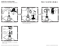
WaterWorks FLLS50 Installation guide
- Category
- Sanitary ware
- Type
- Installation guide

PRODUCT SUPPORT | 800.927.2120 | WATERWORKS.COM PAGE 1 OF 5 | UPDATED ON 2.01.2023
ONE HOLE LAVATORY FAUCETS
INSTALLATION GUIDELINES
TECHNICAL DETAILS:
DETAIL SPECIFICATION
DRAIN DEPTH 3/8” [10mm] MINIMUM - 2” [51mm] MAXIMUM
DRAIN HOLE DIAMETER ø1-1/2” [38mm]
DRAIN STYLE PUSH-TOUCH
INLET CONNECTION 3/8” COMPRESSION CONNECTOR HOSES †
SPOUT REACH 6” [152mm]
WATER PRESSURE 20psi [1.5 bar] MINIMUM - 85psi [6.0 bar] MAXIMUM
WATER PRESSURE RECOMMENDED 45psi [3.0 bar]
† For INTERNATIONAL USE ONLY, two 9/16”-24 UNEF MALE x 3/8” FEMALE BSPP ADAPTERS
STYLE No. UNUK08 and RUBBER WASHERS are provided.
IMPORTANT:
To ensure this product is installed properly, you must read and
follow these guidelines.
The owner/user of this product must keep this information for
future reference.
This product must be installed by a professional licensed
contractor.
Be sure your installation conforms to all federal, state, and local
codes. In the State of Massachusetts, all installations must comply
with the rules and regulations set forth within 248 CMR.
Inspect this product to ensure you have all the parts required for
proper installation.
This product is sold partially assembled but shown fully
disassembled for illustrative and service purposes only.
CAUTION:
●Flushing the SUPPLY VALVES (sold separately) prior to
installing the LAVATORY FAUCET is recommended. Flushing
can prevent damage to the CARTRIDGE and other internal
components.
Use only a strap wrench or protected/smooth-jaw wrench on any
finished surface.
The use of certain plumber’s putty may stain stone or tile surfaces.
If further assistance is required, please contact Product Support
at 1-800-927-2120 Monday through Friday, 8am – 6pm EST.
Refer to the separate Service Parts Documents for available
replacement parts.
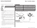
STYLES
FLLS50
FLYTE ONE HOLE LAVATORY FAUCET WITH LEVER HANDLE
HANDLE
[RIGHT HAND
INSTALLATION
ONLY]
OFF
180°
FULL HOT
HANDLE OPERATION:
This product is equipped with a PROGRESSIVE MIXING CARTRIDGE.
The HANDLE rotates a 1/2 turn counterclockwise through cold, warm, and hot water
temperatures as shown above.
MOUNTINGMOUNTING
SURFACESURFACE
3-3/4"
[95mm]
MAX DECK
THICKNESS
Ø 1-3/8"
[35mm]
FITTINGS
HOLE

PRODUCT SUPPORT | 800.927.2120 | WATERWORKS.COM PAGE 2 OF 5 | UPDATED ON 2.01.2023
ONE HOLE LAVATORY FAUCETS
INSTALLATION GUIDELINES
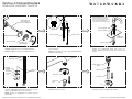
1. Remove the BARREL NUT, METAL WASHER, and
RUBBER WASHER from the THREADED ROD.
NOTE: Do NOT remove the THREADED ROD.
2. Thread and securely tighten the SUPPLY HOSES
into the SPOUT.
NOTE: The HOSES are M10 x 3/8” COMPRESSION
CONNECTOR HOSES.
3. Slide the ESCUTCHEON and WASHER over the
HOSES and THREADED ROD then insert the
SUPPLY HOSES through the hole on the mounting
surface.
4. Slide the RUBBER and METAL WASHERS back
onto the THREADED ROD then thread and securely
tighten the BARREL NUT onto the ROD.
NOTE: Ensure the WASHERS fit properly around
the HOSES.
5. Remove the AERATOR from the SPOUT using the
AERATOR KEY provided.
6. Unthread and remove the NUT, TAILPIECE, and
GASKET from the LOWER DRAIN BODY.
SUPPLY HOSE SUPPLY HOSE
SUPPLY HOSE
MOUNTING
SURFACE
FOAM WASHER
ESCUTCHEON†
SPOUT
A FOAM WASHER for the
ESCUTCHEON is provided. If
desired, a bead of caulk or
clear silicone may be applied
where the ESCUTCHEON
contacts the mounting surface.
†
RUBBER
WASHER
THREADED ROD
METAL
WASHER
BARREL
NUT
SUPPLY
HOSE
SPOUT
AERATOR
AERATOR
KEY
NUT
TAILPIECE
GASKET
LOWER DRAIN
BODY
THREADED ROD
[M8 THREAD]
[DO NOT REMOVE]
RUBBER WASHER
METAL WASHER BARREL NUT
[M8 THREAD]

PRODUCT SUPPORT | 800.927.2120 | WATERWORKS.COM PAGE 3 OF 5 | UPDATED ON 2.01.2023
ONE HOLE LAVATORY FAUCETS
INSTALLATION GUIDELINES
7. Remove the DRAIN STOPPER from the DRAIN
FLANGE then unthread the SCREW from the
LOWER DRAIN BODY.
NOTE: Do NOT remove or discard the LOWER
DRAIN GASKET.
8. Set the DRAIN FLANGE into the LAVATORY (sold
separately) using putty or a clear silicone.
9. Insert the SCREW provided into the FLANGE then
thread and securely tighten the SCREW into the
LOWER DRAIN BODY making sure the LOWER
DRAIN GASKET makes a full seal on the underside
of the LAVATORY.
10. Re-install the DRAIN STOPPER and TAILPIECE
using the GASKET and NUT provided.
11. Make final P-TRAP (sold separately) connections. 12. Connect the SUPPLY HOSES to the SUPPLY
VALVES (sold separately).
NOTE: The HOSES are connected to SUPPLY
TUBES that are marked BLUE for cold and RED for
HOT.
LOWER DRAIN
GASKET
LOWER DRAIN
BODY
UPPER DRAIN
GASKET
[CAN BE
DISCARDED]
DRAIN FLANGE
SCREW
DRAIN
STOPPER LAVATORY
[SOLD SEPARATELY]
DRAIN
FLANGE *
* USE PUTTY OR A
CLEAR ADHESIVE
SILICONE LOWER DRAIN BODY
LOWER DRAIN GASKET
DRAIN
FLANGE
SCREW
NUT
TAILPIECE
GASKET
LOWER DRAIN
BODY
DRAIN
STOPPER
P-TRAP
[SOLD SEPARATELY]
TAILPIECE
SUPPLY VALVE
[SOLD SEPARATELY]
SUPPLY HOSE

PRODUCT SUPPORT | 800.927.2120 | WATERWORKS.COM PAGE 4 OF 5 | UPDATED ON 2.01.2023
ONE HOLE LAVATORY FAUCETS
INSTALLATION GUIDELINES
FOR INTERNATIONAL INSTALLATIONS ONLY:
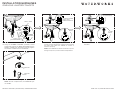
13. Using the RUBBER WASHERS provided, thread
and securely tighten the BSPP ADAPTERS onto the
SUPPLY VALVES then thread and securely tighten
the SUPPLY HOSES onto the ADAPTERS.
14. Turn on the water supply and operate the HANDLE
to flush out the supply lines. Inspect all connections
for leaks then close the DRAIN to ensure it
functions properly.
NOTE: The HANDLE will rotate clockwise a 1/2 turn
through cold, warm, and hot water temperatures.
15. Close the HANDLE then open the DRAIN to drain
the water.
16. Re-install the AERATOR using the tool provided.
NOTE: To order a replacement, use AERATOR style
no. 104284.
2. OPEN
DRAIN
1. CLOSE HANDLE
AERATOR
AERATOR
KEY
SPOUT
2. CLOSE
DRAIN
1. TURN ON WATER
SUPPLY AND
OPERATE HANDLE
SUPPLY VALVE
[SOLD SEPARATELY]
SUPPLY HOSE
RUBBER
WASHER
BSPP
ADAPTER

PRODUCT SUPPORT | 800.927.2120 | WATERWORKS.COM PAGE 5 OF 5 | UPDATED ON 2.01.2023
ONE HOLE LAVATORY FAUCETS
SERVICE GUIDELINES
SPOUT
SET
SCREW
[2mm HEX]
THREADED
ROD
SET SCREW
[2mm HEX]
GLAND COVER
HANDLE
SERVICING SPOUT AND CARTRIDGE:
1. Loosen the SET SCREW and remove the SPOUT.
2. Loosen the SET SCREW and remove the HANDLE.
Unthread and remove the THREADED ROD then
remove the GLAND COVER.
CARTRIDGE
EXTERNAL
O-RING
RETAINING
COLLAR
[DO NOT DISCARD]
HANDLE
HUB
O-RINGS
SPOUT
POST
4. Unthread and remove the RETAINING COLLAR
then remove the CARTRIDGE.
NOTE: To order a replacement, use CARTRIDGE
style no. 057322.
3. Unthread and remove the SPOUT POST then
remove the HANDLE HUB.
-
 1
1
-
 2
2
-
 3
3
-
 4
4
-
 5
5


WaterWorks FLLS50 Installation guide
- Category
- Sanitary ware
- Type
- Installation guide
Ask a question and I''ll find the answer in the document
Finding information in a document is now easier with AI
Related papers
-
WaterWorks BLS47E Installation guide
-
-
-
-
-
-
-
-
-
Other documents
-
American Standard 7420.101.295 Installation guide
-
American Standard 7440.101.002 Installation guide
-
-
JADO Victorian Widespread Lavatory Set Installation guide
-
American Standard 7415.821 User manual
-
-
-
-
-