Page is loading ...

FL-BDPSF-PROCESS (d0076) manual Page 1
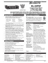
Smart 4-20mA/0-10V process
Tri or Mono-
color digital bargraph with four fully program-
mable set points and
Isolated 4-20 mA analog output capability
• StandardInputRnage
–4-20mA
IP01:
4-20mA Process Loop
IP02:
4-20mA Process Loop with Excitation 24VDC@100mA
–0-10V
ID01:
DC-Volts 2/20/200V with 24V DC Exc
ID05:DC-Volts 2/20/200V with offset and 24V DC Exc
•
Optional isolated 16 bit analog output. User or factory scalable to 4
to 20 mA, 0 to 20 mA or 0 to 10 V across any desired digital span
from ± one count to the full scale range of -1999 to 9999.
•
A Programmable Tricolor (Red-Green-Orange) or mono color (red or
green), 101 segment high brightness bargraph. Vertical or optional
horizontal format.
•
Red 4-digit LED display with a range of -1999 to 9999. Optional
green digital display.
•
Front panel LED annunciators provide indication of setpoint status.
•
Two 9 Amp Form C, and two 4 Amp Form A relays available
•
Provision to connect an external programming lockout switch.
•
Provision for external DIM switch to reduce the brightest
display setting by 50%.
•
Optional NEMA-4 front cover.
•
Automatic intelligent averaging, smooths noisy signals while
providing a fast display response to real level changes.
• ULListed
General Features Specifications
Index
FL-BDPSF-PROCESS
• Thebargraphcandisplay,full
scale, any desired portion of
the digital reading.
•
Bargraph center zero function.
•
Four programmable setpoints
with adjustable Hysteresis.
• Setpoint1hasdelay-on-make
and delay-on-break plus
a special “pump on pump
off” mode that creates a
Software Features
HysteresisBandbetweenSP1
andSP2.
• Relayactivationcanbeselect-
ed to occur above (hi) or below
(Lo) each setpoint.
• Digitaldisplayblanking.
• Decimalpointsetting.
• Four-levelbrightnesscontrol
accessed by the button and
adjusted by the
button.
BargraphCenterPointDisplayModeSelection ... 6
Bargraph Color Programming Mode ........ 9
Case Dimensions ....................... 7
Component Layout..................... 11
Connector Pinouts ..................... 10
Connectors........................... 11
Controls and Indicators .................. 2
CustomFaceplatesandScales ........... 19
DecimalPointandBrightnessSelection ..... 5
Programming Conventions................ 2
SetpointSetting&RelayConfigurationMode....8-9
SoftwareFeatures ...................... 1
SoftwareLogicTree ..................... 3
Specifications.......................... 1
StandardFaceplatesandScales .......... 18
TwoPointAnalogRangeSetting&Calibration .... 7
Two Point Digital Calibration Mode ......... 4
DigitalSpanSelectionforDisplay .......... 5
DigitalSpanSelectionforAnalogRangeOutput... 6
Functional Diagram .................... 10
General Features ....................... 1
I-SeriesInputSignalConditioningModules ...12-15
Input Module Calibration Procedures ...... 17
Input Module Component Glossary........ 16
Ordering Information ................... 20
Pin Descriptions ....................... 10
Input Specs:��������������Seriesconnectionto4-20mAprocess
looporSingleended0-10VDC
A/D Converter:����������14bitsingleslope
Accuracy:������������������±(0�05%ofreading+2counts)
Temp. Coeff�:�������������100ppm/°C(Typical)
Warm up time:�����������2minutes
Conversion Rate:������10conversionspersecond(Typical)
Digital Display:����������
4 digit 0.31" LED red (std),green(optn)
Range
-1999to9999counts�
Bargraph Display:�����
101 segment 4” red vertical (std),
greenortricolor(optn),horizontal(optn)
Polarity:���������������������Assumedpositive�Displays–negative
Decimal Selection:����Frontpanelbuttonselectable,X•X•X•X•
Positive Overrange:� � Bargraphandtopsegmentsofdigital
displayflash�
Negative Overrange:Firstsegmentofbargraphandbottom
segmentsofdigitaldisplayflash�
Relay Output:������������Two4AmpFormArelaysandTwo
9AmpFormCrelays�
Analog Output:���������Isolated16bituserscalablemAorV
OIC(mAout)�����������
4-20mA@0to500Ωmaxloopresistance
OIV(voltsout)���������� 0-10VDC@500Ωorhigherresistance
Power Supply:�����������AC/DCAutosensingwiderangesupply
PS1 (std)����������������
85-265 VAC / 95-300 VDC, 50-400Hz 4.2W
PS2�������������������������
18-48VAC/10-72VDC,50-400Hz4�2W
Operating Temp�:������0to50°C
Storage Temp:�����������–20°Cto70°C
Relative Humidity:����95%(noncondensing)
Case Dimensions:����
9/64DIN(Bezel36Wx144Hmm)
Depthbehindbezel(5�83")148mm
Plus(0�7”)18mmforconnectors
Weight:�����������������������9�5oz�,12ozwhenpacked
101 Segment, 4 Digit 0.32” LEDs
in a 9/64 DIN CASE
Built-in Programmable Scale Factor
No Input required to calibrate

Page 2 FL-BDPSF-PROCESS (d0076) manual
Front Panel Buttons
Program Button
The
P
button is used to move from one program step to the next.
When pressed at the same time as the button, it initiates the
calibration mode. When pressed at the same time as the but-
ton, it initiates the setpoint setting mode.
UP
Button
DOWN
Button
PROGRAM
Button
LED
Annunciators
forSetpoints
1-4
SevenSegment
LED Display
101Segment
Bargraph
Up Button
When in the operational display, pressing the button allows you
to view the setting of the saved Peak and Valley Values.
When setting a displayed parameter during programming, the
button is used to increase the value of the displayed parameter.
Down Button
When in the operational display, pressing the button allows you
to change the Brightness Level as well as to view the setting of
the setpoints SP1, SP2, SP3 & SP4.
When setting a displayed parameter during programming, the
button is used to decrease the value of the displayed parameter.
Front Panel LED Display
Annunciator LEDs
The annunciator LEDs indicate the alarm status. They are labeled
frombottomtotop:SP1,SP2,SP3,SP4.
Digital LED Displays
The digital LED displays are used to display the meter input
signal readings. They also display the programming settings
during programming.
Setpoint Indication
The position of setpoints on the bargraph display are indicated by
an ON or OFF segment dependent on the bargraph display being
above or below the setpoint.
Setpoints
indicated
by an ON
Segment
Setpoints
indicated
by an OFF
Segment--
Controls and Indicators
This symbol represents the
OPERATIONALDISPLAY.
This is the PROGRAM button.
This is the UP button.
This is the DOWN button.
When a button is shown, press and
release it to go onto the next step in the
direction indicated by the arrow. When
an alternative dotted line is shown, this
indicates that an alternative logic branch
will be followed when a particular option
is present.
When two buttons are shown side by side
and enclosed by a dotted line, they must
be pressed at the same time then released
to go onto the next programming step.
If an X appears through a digit, it means that
any number displayed in that digit is not rel-
evant to the function being explained.
P
[Span]
[10000]
P
P
When the
and
buttons are shown
together, the display value can be increased
by pressing and releasing the
button
or decreased by pressing and releasing the
button.
When the
and
buttons are shown
with two displays, either display can be
selected by pressing and releasing the
or
buttons.
When two displays are shown together
with bursts, this indicates that the display is
toggling (flashing) between the name of the
function and the value.
Text or numbers shown between square
brackets in a procedure indicate the pro-
gramming code name of the function or the
value displayed on the meter display.
When there are more than two display selec-
tions they are shown in brackets below the
first display and are also selectable by
pressing and releasing the
or
buttons.
A dotted line enclosing an entire logic dia-
gram indicates that programming branch
will appear only when a particular option is
present.
To explain software programming procedures, logic diagrams are
used to visually assist in following the programming steps. The
following symbols are used throughout the logic diagrams to
represent the buttons and indicators on the meter:
Programming Conventions
[X•XXX]
[XX•XX]
[XXX•X]
[XXXX•]
[XXXX]

FL-BDPSF-PROCESS (d0076) manual Page 3
The FL-BDPSF-PROCESS is an intelligent bargraph meter with
a hierarchical software structure designed for easy programming
and operation, as shown below in the software logic tree.
Software Logic Tree
Peak
Reset
PEAK
Reset
VALY
Valley
[orAn]
[rEd]
NOTE: Will only
appear if a tricolor
display is installed
[orAn]
[rEd]
[orAn]
[rEd]
[orAn]
[rEd]
[orAn]
[rEd]
BARGRAPH COLOR
PROGRAMMING MODE
See Page 9
Tricolor Bargraph
The tri-color bargraph is designed
like a traffic light, to display either
red, orange or green, but only one
color at a time. The color to be
displayed is selected in two ways.
The first step is to select the color
to be displayed when the bar is
“below” whichever set point is set to
the lowest position.
The second step is to select the
color to be displayed when the bar
is above each specific setpoint,
regardless of the order or position
to which the set points are set.
However, if two or more setpoints
with differently specified colors are
positioned at the same set point
value, the color specified for the set
point with the highest identifying
number will be displayed. When
setpoints are set to the same value,
the SP4 color overrides the SP3
color, the SP3 color overrides the
SP2 color, and the SP2 color
overrides the SP1 color.
[rLYS] (h) High
the relay
energizes
when the
setpoint is
exceeded.
(L) Low
the relay
energizes below
the setpoint.
(–) Disabled
the relay will be
diabled and
removed from
the menu.
Pump On Pump Off
When PUM is selected ON,
and SP2 is set at a value
higher than SP1, the SP1
relay will operate in
a special "pump on pump off"
Hysteresis mode. SP2 acts
as the upper limit and SP1
acts as the lower limit of the
Hysteresis Band.
For filling applications, rLYS
should be set to LhLh. SP1 will
then activate for inputs less than
the SP1 setpoint, and remain
ON until the SP2 setpoint is
reached.
For emptying applications,
rLYS should be set to hhhh.
SP1 will then activate for inputs
greater than the SP2 setpoint,
and remain ON until the SP1
setpoint is reached.
Operational Display
MAIN MENU
PEAK & VALLEY
VIEW & RESET
BRIGHTNESS AND
SETPOINT VIEW MODE
Bargraph Center Point
Display Selection (cto)
This branch will
only appear if
the analog
output option
is installed
Back to
Operational
Display
Digital Display
ON/OFF
Selection (diSP)
Sub-menu MODE
Calibration
Input
Calibration
Output
Calibrate Analog
Output Lo
Calibrate Analog
Output Hi
Select the Digital
Reading at which
the Analog Output
Hi (chi) will occur
Select the Digital
Reading at which
the Analog Output
Lo (cLo) will occur
This branch will only
appear if the analog
output option
is installed
DIGITAL SPAN SELECTION
FOR ANALOG RANGE OUTPUT
See Page 6
DIGITAL DISPLAY ON/OFF
See Page 6
BARGRAPH CENTER POINT
DISPLAY MODE SELECTION
See Page 6
TWO POINT ANALOG OUTPUT
RANGE SETTING AND CALIBRATION
See Page 7
Set the Decimal
Point (dp)
Bargraph Display
Scale Lo Range
Setting (bLo)
Bargraph Display
Scale hi Range
Setting (bhi)
[X•XXX]
[XX•XX]
[XXX•X]
[XXXX•]
[XXXX]
DECIMAL POINT AND
BRIGHTNESS SELECTION
See Page 5
DIGITAL SPAN SELECTION
FOR BARGRAPH DISPLAY
See Page 5
Goes directly
to Zero setting
if Analog Output
is not installed
+
–
4.00
+
–
20.00
1 Dimmest
2 Dim
3 Bright
4 Brightest
SETPOINT SETTING AND
RELAY CONFIGURATION MODE
See Page 8
L, h or –
L, h or –
L, h or –
L, h or –
Relay Activation
& Relay Disable
PROGRAMMABLE
OFFSET AND
SCALE FACTOR
See Page 4
Offset
Scale
Factor
Display
Brightness (br)
1 Dimmest
2 Dim
3 Bright
4 Brightest
Delay-on-Make
[doM]
Delay-on-Break
[dob]
0 to 9999
seconds
0 to 9999
seconds
Set Setpoint 1
[SP1]
Delay-on-Make
[doM]
Delay-on-Break
[dob]
0 to 9999
seconds
Setpoint 2
[SP2]
0 to 9999
seconds
Pump
[PUM]
Hysteresis
[hYSt]
Hysteresis
[hYSt]
Hysteresis
[hYSt]
Hysteresis
[hYSt]
Setpoint 3
[SP3]
Setpoint 4
[SP4]
This branch will only
appear if the Programming
Lock is engaged
This branch will only appear if the
Programming Lock is engaged.
When Lock is engaged, values
can be viewed, but not changed.
Calibration
Mode
Software Version is Displayed on Power-up
When power is applied, all segments of the bargraph and dig-
ital display light up for 3 seconds. The version number of the
installed software is then displayed for 2 seconds, after which,
the operational display indicates the input signal.
15 Second Program Timeout
ExceptforZEROandSPANsettingsintheTwoPointDigitalCalibrationMode
andtheAnalogOutputRangeSettingandCalibrationMode(cLoandchi),the
meter has a 15 second program timeout. If no buttons are pressed for 15
seconds in any of the other programming sequences, the meter will exit the
programming mode and return to the operational display. Any program chang-
es that were made prior to pressing the
P
button in the preceding step will
not be saved.

Page 4 FL-BDPSF-PROCESS (d0076) manual
STEP A Enter the Calibration Mode
1) Pressthe
P
and buttonsatthesametime�Displaytog
glesbetween[CAL]and[oFF]�
2)
Pressthe or button�Displaychangesfrom[oFF]to[on]�
3)
Press the
P
button� Display toggles between [CAL]
and [out]�
Note: If at this point, the display skips directly to STEP C and toggles
between[SPAn] andthe previous[SPan] setting,the software
is detecting that the optional analog output hardware is NOT
installed�
STEP B Select Two Point Digital Calibration of Input Signal
1) Pressthe or buttontoselectCAL[iP]forinputsignal
calibration�
2) Pressthe
P
button�Displaytogglesbetween[oFFS]andthe
previousoffsetsetting�
STEP C Set the Offset on the Digital Display
1) Usingthe and buttons,adjustthedigitaldisplaytothe
desiredoffset�Thisisthereadingthatthemeterwilldisplay
forazeroinput
2) Pressthe
P
button�Displaytogglesbetween[ScAL]andthe
previousScalefactor�
STEP D Set the Scale factor on the Digital Display
1)
Usingthe and buttons,adjustthemeterdisplayto
the desired Scale factor� The default value is 2000, for
which a2Vinputwillread2000�Ifthescalefactoris
changedthe display will change proportionately�
ThereforeiftheScale factor is changed to 1000
thenforthesame2Vinputthedis play would read
1000�
2) Pressthe
P
button�
The Digital Rescaling is now complete�
Ifthe DigitalRescaling wassuccessfully completed,the menu
branches to the Digital Span Selection for Bargraph Display
(see page 6), and the display flashes [bhi] and the previous
setting�
TheFL-BDPSF-PROCESSmetermayberescaledwithoutapplyinganexternalsignalbychangingtheOffsetandScalefactor�
Offsetisthereadingthatthemeterwilldisplayforazeroinput�TheOffsetmaybesettoanyvaluefrom-1999to+9999�The
defaultvalueoftheOffsetis000
Scalefactoristhegainofthemeter�ThedisplayedreadingisdirectlyproportionaltotheScalefactor�Thedefaultvalueofthescale
factoris2000,butitmaybesettoanyvaluebetween-1999and+9999�
Foraninputof2Vacalibratedmeterwillread2000withthedefaultScalefactorof2000,3000withaScalefactorof3000and500
withaScalefactorof500
Ifalinearscaleisrepresentedbymx+b,thentheScaleFactorcorrespondstotheslope‘m’andtheOffsetcorrespondstothe
intercept‘b’
TheinternalSignalSpanislimitedto3VDCbetween–1VDCto+2VDC�OutputsfromanInputSignalConditioningmodule
thatexceedtheselimitswillcausethemetertoindicateoverrange�
Note:Mostinputsignalconditionershaveprovisionsforanalogcalibrationandscaling�Ifthemeter’sdigitalScaleFactorissetto
2000andOffsetsetto0000then,anypre-calibratedsignalconditionerwithanoutputthatdoesnotexceed–1Vto+2V,willread
correctlyinthemeterwithoutanyfurthercalibration�
Digital Rescaling
Digital Rescaling Procedure
MAIN MENU
Operational Display
Sub-menu
MODE
STEP A Calibration
Mode
STEP B Calibration
Mode
STEP C Offset
STEP D Scale
Factor
To Digital Span Selection for
Bargraph Display Page 6
cAL out/iP branch will only
appear if the analog output
option is installed, otherwise
cAL on goes directly to ZEro
setting
DIGITAL
RESCALING MODE
To Digital Span Selection
for Bargraph Display
See Page 7
To Two Point Analog
Output Range Setting
and Calibration
See Page 8

FL-BDPSF-PROCESS (d0076) manual Page 5
Example
Example
From Digital
Rescaling Mode
See Page 4
STEP A
STEP B
STEP C
See Example Above
of Bargraph Display
Scale Range
DIGITAL SPAN SELECTION
FOR BARGRAPH DISPLAY
[X•XXX]
[XX•XX]
[XXX•X]
[XXXX•]
[XXXX]
DECIMAL POINT AND
BRIGHTNESS SELECTION
STEP D
To Digital Span Selection
for Analog Range Output or
Bargraph Center Point
Display Mode Selection
on Page 6
STEP A Enter the Calibration Sub Menu Mode
1) Pressthe
P
and buttons at thesametime� Displaytoggles
between[CAL]and[oFF]�
2) Press the
P
button� Display toggles between [bhi] and the
previoussetting�
STEP B Set the Digital Span of the Bargraph Display (See example above)
1) Using the and buttons, adjust the display to the desired
highparameterreading,e�g�6000counts�
2) Press the
P
button� Display toggles between [bLo] and the
previoussetting�
3) Using the and buttons, adjust the display to the desired
lowparameterreading,e�g�4000counts�
4) Pressthe
P
button�Displaychangesfrom[4000]to[dP]�
STEP C Set the Decimal Point
1) Usingthe and buttons,adjustthedisplaytothedesired
decimalpointsetting�
2) Press the
P
button� Display toggles between [br] and the
previousbrightnesssetting�
STEP D Set the Bargraph and Digital Display Brightness
1) Usingthe and buttons,adjustthedisplaytothedesired
brightnesssetting(4isthebrightestsetting)�
2) Pressthe
P
button�Displaytogglesbetween[Anhi]andthe
previous[Anhi]setting�
Note: If at this point, the display skips directly to STEP G and toggles
between[Cto]and[oFF],thesoftwareisdetectingthattheoptionalanalog
outputhardwareisNOTinstalled�
Digital Span Selection For Bargraph Display
Decimal Point and Brightness Selection
Bargraphdoesnotlightupfor
InputSignalsupto3999counts
BargraphlightsupforInput
Signalsabove4000counts
No bargraph
display
Digital display Digital display
%
100
0
10
30
50
70
90
20
40
60
80
4
3
2
1
P
SP
Bargraph display
ends at
6000 counts
Bargraph display
starts at
4000 counts
At 5000 counts
the bargraph display
will be at midpoint
%
100
0
10
30
50
70
90
20
40
60
80
4
3
2
1
P
SP
Example of Setting the Digital Span of the Bargraph Display
to be Different than the Digital Display Range
The bargraph can be set to display full scale (0-101 bars) any portion
of thedigitalreading froma minimumof 100 counts to a maximum of
12,000 counts� This provides higher resolution bargraph indication for
thoseapplicationswherethenormaloperatinginputsignalrangeisless
thanthedesiredfullscaledisplayrangeofthedigitaldisplay�
For Example:
If the full scale range of the meter has been set from -1999 to
9999 (0-12,000 counts), but the normal operating range of the
input signal is between 4000 & 6000. The bargraph high parame-
ter [bhi] can be set to 6000 and the bargraph low parameter [bLo]
can be set to 4000.
This means that although the meter could digitally display a signal
from -1999 to 9999 (0-12,000 counts), the bargraph display only
begins to function at a reading of 4000, and reaches full scale
indication at a reading of 6000. Although the digital display will
continue reading up to 9999 before indicating overrange, the bar-
graph display will indicate its overrange by flashing for readings
above 6000.

Page 6 FL-BDPSF-PROCESS (d0076) manual
5000
Center
Point
Single
Bar Lit
0
2500
5000
Center
Point
0
2500
4000
As signal
increases
0
5000
Center
Point
2500
1000
As signal
decreases
+ 1 V
Center
Point
Single
Bar Lit
- 1 V
0 V
+ 1 V
Center
Point
- 1 V
0 V
0.800
As signal
increases
+ 1 V
- 1 V
0 V
Center
Point
-0.800
As signal
decreases
Example of Using the Center Point Bargraph Display Mode
with a Unipolar Input
Ifthemeter'sfullscalerangeissetto5000counts,themidpointwouldbe
2500counts�Ifasignalof2500countsisappliedonlyonesegmentatthe
2500countmarkwilllightup�Ifasignalof4000countsisappliedtheseg-
mentsbetweenthecentersegment(2500counts)andthe4000countmark
lightup�
Ifasignalof1000countsisapplied,thesegmentsbetweenthecenterseg-
ment(2500counts)andthe1000countmarkwilllightup�
Example of Using the Center Point Bargraph Display Mode
with Bipolar Signal Inputs
Themetermayalsobecalibratedtodisplaysymmetricalbipolarsignalssuch
as±1Vor±10V�Whenthecenterpointdisplaymodeisselected,itwill
thenfunctionasacenterzerometer�Whenpositivesignalsareapplied,the
barwillgoupfromthecenterpoint,andwhennegativesignalsareapplied,
thebarwillgodownfromthecenterpoint�
STEP E Selecting the [Anhi] Digital Value for Analog High Output
1) Usingthe and buttons,adjustthedisplaytothedesireddigital
valueatwhichthe[chi]CalibratedAnalogHighoutputwilloccur�For
digitalreadings outsidethe digitalspan selected,the analogoutput
willlinearlyriseabovethevaluesetforchi,uptothemaximumanalog
outputcapability�However,theanalogoutputwillnotgolowerthan
thecalibratedvaluesetforcLo(seebelow)�
2) Pressthe
P
button�Displaytoggles between [AnLo] and previous
[AnLo] setting�
STEP F Selecting the [AnLo] Digital Value for Analog Low Output
1) Usingthe and buttons,adjustthedisplaytothedesired
digital value at which the [cLo] Calibrated Analog Low output will
occur� For Digital readings outside the Digital Span selected, the
analogoutputwillnotgolowerthanthecalibratedvaluesetforcLo�
2) Pressthe
P
button�Thedisplaytogglesbetween[cto]and[oFF]�
Note:Anytwodigitalspanpointsfrom–1999to9999canbeselected�Thedigital
valuesfor[Anhi]analoghighand[AnLo]analoglowcanbereversedtoprovidea
20to4mAoutput�Thedigitalspanselectedcanbeassmallastwocounts,when
usingtheanalogoutputtofunctionasaControlorAlarmDriver�Smalldigitalspans
willcausethehighresolution16bitDtoAtoincrementdigitallyinstaircasesteps�
SeeTwoPointAnalogOutputRangeSettingandCalibrationatthetopofthenext
page�
Digital Span Selection for Analog Range OutputDigital Span Selection for Analog Range Output
Bargraph Center Point Display Mode Selection
STEP G Bargraph Center Point Mode Selection (See example above)
1) To select bargraph center point mode, press the or
button�Displaychangesfrom[oFF]to[on]�
2) Pressthe
P
button�Displaytogglesbetween[diSP]and[on]
or[oFF]�
STEP H Digital Display ON/OFF Selection
1) Tosetthedisplayto[oFF],pressthe or button�Display tog-
glesbetween[diSP]and[oFF]�
2) Pressthe
P
button�Thedisplayexitsthecalibrationmode
and returns to the operational display� Only the bargraph
displayisonandthedigitaldisplayisoff�
Ifthedigitaldisplayisselectedtobeoff,pressinganybuttonto
makeprogrammingchangesortoviewsetpointsactivatesthedigitaldisplay�When
theprocedureiscomplete,thedigitaldisplaywillthenautomaticallyswitchoff�
The Display/Bargraph settings are now complete.
STEP G
See Example of Bargraph
Center Point Display Mode
Selection Above
Operational Display
STEP H
From Digital Span Selection
for Analog Range Output Above
or Direct From Decimal Point
and Brightness Selection Page 5
if Analog Output Option is Not Present
BARGRAPH CENTER POINT
DISPLAY MODE SELECTION
Digital Display On/Off
STEP E
STEP F
This branch will only
appear if the analog
output option is installed
To Bargraph Center
Point Display Mode
Selection Below
From Decimal Point and
Brightness Selection
See Page 5
DIGITAL SPAN SELECTION
FOR ANALOG RANGE OUTPUT

FL-BDPSF-PROCESS (d0076) manual Page 7
Clear Lockable NEMA 4X
Splash Proof Lens Cover
P/N.(OP-N4/144X36 )
133.5mm
(5.27")
Mosaic
Fitting
9/64 DIN
cutout
spacer
To open rear cover,
use a small flat
blade screw driver.
Press down lightly
to release catch and
leaver outwards.
SIDE VIEW
137.7mm
(5.42")
9/64 DIN
cutout
spacer 142.3mm
(5.62")
Max. panel thickness
43mm
(1.7")
For additional strength,
extra Mounting Slide Clips
can be ordered and doubled up
one behind the other.
P/N. (75-DMC144X36)
4.5mm
(0.18")
Metal Surround Case
P/N.(OP-MTL144X36) is pre-installed
at the factory and cannot be removed
without damage to the case.
Two bezel Trim
Strips are supplied with
each Panel Adaptor
Panel Adaptor to fit existing 6" Edgewise
Pointer Meter Cut-Outs P/N.(OP-PA/144x36)
Adaptor uses wide jaw mounting slide
clips.P/N.(75DMC14436B)
When extra panel
mounting tightness is
required,
order the optional
screw mount
clip.
P/N.(OPMTLCLIP)
FRONT VIEW
144mm
(5.69")
36mm
(1.42") 4mm
(0.16")
typical
9/64 DIN
36x144 mm
100
0
10
30
50
70
90
20
40
60
80
4
3
2
1
P
SP
PANEL CUTOUT
138mm
(5.45")
33mm
(1.3")
Snug
Fitting
Loose
Fitting
8 places
7.5mm(0.3")
3.5mm(0.14")
4 places
4 places
32.2 mm
(1.27")
Mosaic
Fitting
133mm
(5.25")
135.2mm
(5.34")
3mm(0.12")
9/64 DIN
cutout
spacer
Case will mount in standard DIN cutouts
Various
bezel colors
are available.
Black is
standard.
The Metal Surround
case uses Metal
Screw Mount Clips
and has a max.
panel thickness
mounting of
7mm(0.28")
TOP VIEW
5mm
(0.20") 117.5mm
(4.64")
18.3mm (0.72")
Straight-thru
Connector
31mm
(1.22")
34mm
(1.34")
Mosaic Fitting
Right-angled
Connector
6mm
(0.24")
10mm
(0.39")
26.5mm (1.05")
Push-On Connector
for FI series IO board
The adapter snaps on
the 36x144 mm
(1.42"x5.69") case and
enables single unit or
stack mounting in an
existing 6" edgewise
pointer meter cut-out.
100
0
25
50
75
100
0
25
50
75
SP1 SP2 SP3 SP4
Zero Span Zero Span
Panel adaptor plates are
available to retrofit most
existing panel cutouts.
31mm
(1.22")
These dimensions are
increased by 2mm (0.08") when
the metal surround case is installed.
For extra strength in portable applications,
the 8 DIN spacers should be snipped
off and the Mosaic fitting cutout used.
Case Dimensions
Operational Display
Sub-menu
MODE
STEP A Calibration
Mode
STEP B Calibration
Mode
STEP E
Calibrate
Analog
Output
Lo
STEP F
Calibrate
Analog
Output
Hi
Will only appear if the analog
output option is installed
To Digital Span Selection
for Bargraph Display
See Page 5
To Two Point Digital
Calibration Mode
See Page 4
Operational Display
TWO POINT ANALOG OUTPUT
RANGE SETTING AND CALIBRATION
+x
–x
4.00
+x
–x
20.00
DetermineiftheAnalogOutputSelectionHeaderisinthe4to20mA(0-20mA)positionorthe0
to 10VDC position. If necessary, the module may have to be removed and the header position
changed (see Component Layout below).
Note: Always disconnect power from the meter before removing the analog output module to
adjust the mA or Volts output selection header and reinstalling it. When power is reconnected, the
meter’s software will automatically detect the presence or absence of the analog output module.
STEP A Enter the Calibration Mode
1) Press the
P
and buttons at the same time. Display toggles between [cAL] and [oFF].
2) Press the or button. Display changes from [oFF] to [on].
3) Press the
P
button. Display toggles between [cAL] and [out] input calibration.
Note: If at this point the display skips directly to toggle between Zero and the previous Zero
setting, the software is detecting that the optional analog output hardware is NOT installed.
STEP B
EntertheTwoPointAnalog[ouT]OutputRangeSettingandCalibrationMode
1) Press the
P
button. Display toggles between [cLo] and an internal scale factor.
STEP E SetorCalibrate[cLo]theLowAnalogValueoftheAnalogOutputRange
1) Connect a multimeter to analog output pins 17 and 18 (see Rear Panel Pinouts
on page 10). Using the and buttons, adjust the analog output to the desired
low value as measured on the multimeter. cLo may be adjusted to any value from
–0.3 mA to 18 mA (mA output selected) or from –0.6 V to 8 V (volt output selected).
However, the output of cLo must always be less than the value selected for chi. If
a reversed analog output is desired, the values selected to establish the Digital
Spancanbereversed(seetopofpage6).FordigitalreadingsoutsidetheDigital
Spanselected,theanalogoutputwillnotgoanylowerthanthecalibratedvalueset
for cLo. However, the analog output will linearly rise above the value set for chi, up
to the the maximum analog output capability (see chi below).
2) Press the
P
button. Display toggles between [chi] and an internal scale factor.
STEP F SetorCalibrate[chi]theHighAnalogValueoftheAnalogOutputRange
1) Using the and buttons, adjust the analog output to the desired high value
as measured on the multimeter display. chi may be adjusted to any value from 18
mA to 24 mA (mA output) or from 8 V to 10.3 V (volt output). However, the value
must be higher than the value selected for cLo. For digital readings outside the
DigitalSpanselected,theanalogoutputwilllinearlyriseabovethevaluesetforchi,
up to the maximum analog output capability.
2) Press the
P
button. The meter exits the calibration mode and returns to the
operational display.
Note: The analog output range established by the values selected for cLo and chi will occur, auto-
matically scaled, between the two digital values selected for AnHi and AnLo. However,
the analog
output can linearly rise above the chi value set for digital readings outside the digital span
selected.SeeDigitalSpanSelectiononpage6.
Two Point Analog Output Range Setting and CalibrationTwo Point Analog Output Range Setting and Calibration

Page 8 FL-BDPSF-PROCESS (d0076) manual
Operational Display
SETPOINT SETTING
AND RELAY
CONFIGURATION MODE
STEP A
STEP B
STEP C
STEP D
No [doM] or [dob]
No [doM] or [dob]
STEP E
STEP F
STEP G
STEP H
STEP I
STEP J
STEP K
STEP L
To Step M of Setpoint
Setting and Relay
Configuration Page 9
The following programming steps are required to enter the setpoint values and configure the relay functions
in a meter with four relays using four setpoints. Generally if less than four relays are installed, the setpoints
without relays are operational in software for tri-color control or display only purposes. To remove unwanted
setpoint indications, set them to 9999 or -1999 depending on the relay activation mode selected.
STEP A Enter the Setpoint Mode
1) Press the
P
and buttonsatthesametime.Displaytogglesbetween[SP1]andtheprevious
SP1setting.
STEP B Set Setpoint 1 [SP1]
1) Using the and buttons,adjustthedisplaytothedesiredSP1value.
2) Press the
P
button. Display toggles between [doM] and the previous [doM] setting.
STEP C Set the SP1 Delay-on-Make [doM] Delay Time Setting
1)
Using the and buttons, adjust the display to the desired [doM] value (0 to 9999 seconds).
The reading must continuously remain in an alarm condition until this delay time has elapsed before
the relay will make contact (energize).
2) Press the
P
button. Display toggles between [dob] and the previous [dob] setting.
STEP D Set the SP1 Delay-on-Break [dob] Delay Time Setting
1)
Using the and buttons, adjust the display to the desired [dob] value (0 to 9999 seconds).
The reading must continuously remain in a non-alarm condition until this delay time has elapsed
before the relay will break contact (de-energize).
2) Press the
P
button.Displaytogglesbetween[hYSt]andtheprevious[hYSt]setting.
STEP E Select the Hysteresis [hYSt]
1)
Using the and buttons, select the Hysteresis to be ON or OFF.
2) Press the
P
button. Display toggles between PUM and (on) or (oFF).
STEP F Select Pump [PUM] (on) or (oFF)
1)
Using the and buttons, select the Pump to be ON or OFF. When PUM is selected ON, and
SP2issetatavaluehigherthanSP1,theSP1relaywilloperateinaspecial"pumponpumpoff"mode.
SP2actsastheupperlimitandSP1actsasthelowerlimitoftheHysteresisBandontheSP1relay.
For filling applications:
[rLYS]shouldbesetto[LhXX](seestepM).TheSP1relayandSP1LEDAnnunciatorwillthenactivateforinputs
lessthantheSP1setpoint,andremainONuntiltheSP2setpointisreached.
For emptying applications:
[rLYS]shouldbesetto[hhXX](seestepM).TheSP1relayandSP1LEDAnnunciatorwillthenactivateforinputs
greaterthantheSP2setpoint,andremainONuntiltheSP1setpointisreached.
2) Press the
P
button.Displaytogglesbetween[SP2]andthepreviousSP2setting.
STEP G Set Setpoint 2 (SP2)
1) Using the and buttons,adjustthedisplaytothedesiredSP2value.
2) Press the
P
button.Displaytogglesbetween[hySt]andtheprevious[hySt]setting.
STEP H Select the Hysteresis [hYSt]
1)
Using the and buttons, select the Hysteresis to be ON or OFF.
2) Press the
P
button.Displaytogglesbetween[SP3]andtheprevious[SP3]setting.
STEP I Set Setpoint 3 (SP3) (No [doM] or [dob])
1) Using the and buttons,adjustthedisplaytothedesiredSP3value.
2) Press the
P
button.Displaytogglesbetween[hySt]andtheprevious[hySt]setting.
STEP J Select the Hysteresis [hYSt]
1)
Using the and buttons, select the Hysteresis to be ON or OFF.
2) Press the
P
button.Displaytogglesbetween[SP4]andtheprevious[SP4]setting.
STEP K Set Setpoint 4 (SP4) (No [doM] or [dob])
1)
Using the and buttons,adjustthedisplaytothedesiredSP4value.
2) Press the
P
button.Displaytogglesbetween[hySt]andtheprevious[hySt]setting.
STEP L Select the Hysteresis [hYSt]
1)
Using the and buttons, select the Hysteresis to be ON or OFF.
2) Press the
P
button.Displaytogglesbetween[rLYS]andthepreviousrelaysetting.
Please Continue On Next Page.
Setpoint Setting and Relay Configuration Mode

FL-BDPSF-PROCESS (d0076) manual Page 9
STEP M
STEP N
STEP O
STEP P
STEP Q
STEP R
STEP S
STEP T
STEP U
[orAn]
[rEd]
NOTE: Will only
appear if a tricolor
display is installed
[orAn]
[rEd]
[orAn]
[rEd]
[orAn]
[rEd]
[orAn]
[rEd]
BARGRAPH COLOR
PROGRAMMING MODE
Operational Display
Operational Display
From From Step L of
Setpoint Setting and Relay
Configuration Page 8
L or h
L or h
L or h
L or h
To comply with the latest safety requirements, the tri-color bargraph is designed like a traffic light, to
display either red, orange or green, but only one color at a time. When the bar reaches a selected
color change point, the entire bar will change to the color designated for that zone. This eliminates any
ambiguity as to the signal status, especially just after transitioning to a new zone.
First (StepQ)istoselectthecolortobedisplayed,whenthebaris“below*”,whicheversetpointisset
to the lowest position.
Second (StepsR,S,T,andU)istoselectthecolortobedisplayedwhenthebarisaboveeachspecific
set point, regardless of the order or position to which the set points are set.
However, if two or more setpoints with differently specified colors are positioned at the same set point
value, the color specified for the set point with the highest identifying number will be displayed. When
setpointsaresettothesamevalue,theSP4coloroverridestheSP3color,theSP3coloroverridesthe
SP2color,andtheSP2coloroverridestheSP1color.
STEP Q Select Bargraph Color when the bar is BELOW* the Setpoint that is set to the lowest
position
1) Using the and buttons, select the desired bargraph color [grn], [oran] or [red]
2) Press the
P
button.Displaytogglesbetween[CSP1]andthepreviouscolorsetting.
STEP R Select Bargraph Color when the bar is ABOVE* SP1 Setpoint
1) Using the and buttons, select the desired bargraph color [grn], [oran] or [red]
2) Press the
P
button.Displaytogglesbetween[CSP2]andthepreviouscolorsetting.
STEP S Select Bargraph Color when the bar is ABOVE* SP2 Setpoint
1) Using the and buttons, select the desired bargraph color [grn], [oran] or [red]
2) Press the
P
button.Displaytogglesbetween[CSP3]andthepreviouscolorsetting.
STEP T Select Bargraph Color when the bar is ABOVE* SP3 Setpoint
1) Using the and buttons, select the desired bargraph color [grn], [oran] or [red]
2) Press the
P
button.Displaytogglesbetween[CSP4]andthepreviouscolorsetting.
STEP U Select Bargraph Color when the bar is ABOVE* SP4 Setpoint
1) Using the and buttons, select the desired bargraph color [grn], [oran] or [red]
2) Press the
P
button. The meter exits the setpoint mode and returns to the operational
display.
The Bargraph Color programming mode is now complete.
STEP M Set Relay Activation mode [rLYS] for SP1
(h) High the relay energizes when the setpoint is exceeded. (L) Low the relay energizes below
thesetpoint.ThesetpointisindicatedfromlefttorightSP1,SP2,SP3,SP4.
1) Using the and buttons,select(L)or(h)forthefirstdigit,whichcorrespondstoSP1.
2) Press the
P
button.TheSP2RelayActivationdigitbeginstoflash,anditsdecimalpointislit.
STEP N Set High (h) or Low (L) for SP2
1)
Using the and buttons,select(L)or(h)fortheseconddigit,whichcorrespondstoSP2.
2)
Press the
P
button.TheSP3RelayActivationdigitbeginstoflash,anditsdecimalpointislit.
STEP O Set High (h) or Low (L) for SP3
1) Using the and buttons,select(L)or(h)forthethirddigit,whichcorrespondstoSP3.
2)
Press the
P
button.TheSP4RelayActivationdigitbeginstoflash,anditsdecimalpointislit.
STEP P Set High (h) or Low (L) for SP4
1)
Using the and buttons,select(L)or(h)forthefourthdigit,whichcorrespondstoSP4.
2) Press the
P
button.
Ifamono-colorredorgreendisplayisinstalledthentheSetpointRelayProgrammingModeisnowcompleteandthe
meter returns to the operational display.
If a tricolor bargraph display is installed then the Bargraph Color Programming Mode will be entered and
display toggles between [CoL] and the previous setting. Color selection menu will be displayed.
Setpoint Setting and Relay Configuration Mode Continued
Bargraph Color Programming Mode
1234
SP
P
*Note: For horizontal display for-
matsBELOW*shouldbereadas,
“totheleft”andABOVE*should
be read as, “to the right”.

Page 10 FL-BDPSF-PROCESS (d0076) manual
Standardplug-inscrewterminalblocksprovidedbyTexmate:
WARNING
AC and DC input signals and power
supply voltages can be hazardous.
Do Not connect live wires to ter-
minal blocks, and do not insert,
remove or handle terminal blocks with live
wires connected.
!
Connectors
!
WARNING: AC and DC input signals and power supply
voltages can be hazardous. Do Not connect live wires to
screw terminal plugs, and do not insert, remove or handle
screw terminal plugs with live wires connected.
SP3
NOSP1/3
COM
SP1
NC SP1
NO
SP4
NOSP2/4
COM
SP2
NC SP2
NO
LOCK
COMM
DIM
SP3 SP4
SP1
COM 1&3
NO3
NC1
COM 2&4
NC2
NO4
NO1
NO2
SP2
8910 11 12 13 14 15 17 18 19 20 21 23 24
1-6
Input Signal
Conditioning Moduls
Analog
Output +
Analog
Output – AC
Neutral AC
Line
– DC + DC
or
This meter uses plug-in type screw terminal connectors for all
input and output connections. The power supply connections
(pins 23 and 24) have a unique plug and socket outline to prevent
cross connection. The main board uses standard right-angled
connectors.
Replacement 2-, 3-, and 4-pin plug connectors are available
(see Accessories on page 20).
Pins 1 to 6 – Input Signal
Pins 1 to 6 are reserved for the input signal conditioner.
Seethedatasheetfortheselectedinputsignalconditioner.
Pins 8 to 15 – Relay Output Pins
Pin 8 SP3 NO. Normally Open 4 Amp Form A.
Pin 9 SP1/3 COM.CommonforSP1andSP3.
Pin 10 SP1 NC. Normally Closed 9 Amp Form C.
Pin 11 SP1 NO. Normally Open 9 Amp Form C.
Pin 12 SP4 NO. Normally Open 4 Amp Form A.
Pin 13 SP2/4 COM.CommonforSP2andSP4.
Pin 14 SP2 NC. Normally Closed 9 Amp Form C.
Pin 15 SP2 NO. Normally Open 9 Amp Form C.
Pins 17 to 21 – Rear Panel Switches
Pin 17 ANALOG OUTPUT (+). mA (0 to 20 mA/4 to 20 mA)
or V (0 to 10 V) output is header selectable.
Pin 18
ANALOG OUTPUT (–). mA (0 to 20 mA/4 to 20 mA)
or V (0 to 10 V) output is header selectable.
Pin 19 Programming LOCK. By connecting the LOCK pin
to the COMMON pin, the meter's programmed
parameters can be viewed but not changed.
Pin 20 COMMON. To activate the LOCK or DIM functions
from the rear of the meter, the respective pins have
to be connected to the COMMON pin. This pin is
connected to the internal power supply ground.
Pin 21 DIM. By connecting the display dim (DIM) pin to
the COMMON pin, the display brightness setting
is halved.
Pins 23 and 24 – AC/DC Power Input
Auto-sensing AC/DC power supply. For voltages between
85-265VAC/95-300VDC(PS1)or18-48VAC/10-72V
DC(PS2).
Pin 23 AC Neutral / –DC. Neutral power supply line.
Pin 24 AC line / +DC. Live power supply line.
Connector Pinouts
Pin Descriptions
Note: The sequence of setpoint outputs is now 3-1-4-2, enabling delay
on make (dom) and delay on break (dob) to be used with both Form
“C” relays.

FL-BDPSF-PROCESS (d0076) manual Page 11
Component Layout
MAIN BOARD
Low Voltage
Hi Voltage
4-20mA INPUT MODULE
0-10V INPUT MODULE
4 to 20mA Process Loop Measurement
Order IP02, if you require the loop
excitation voltage (24VDC@100mA)
to be supplied by the meter.
24V
External
Loop Supply
Common
ZERO
SPAN
Oset PROCESS 4/20 mA
0
+
_
Other devices can be
added to the loop.
Direction
Of
Current
<Decrease Zero Increase >
<Decrease Span Increase >
Range
HI
LO
OFF
ON
24V EXC
Fully User Scalable
PIN 2
PIN 1
PIN 3
+_
Exc�On/Off
Header
SPANPot
HI/LOW
SPANRANGE
Header
ZEROPot
ZEROADJUSTHeader
SPANADJUST
Header
ZEROOFFSET
RANGEHeader
<DecreaseIncrease>
<DecreaseIncrease>
Lo
Hi
OFF
ON -
0
+
InputRange
Header
Exc�On/Off
Header
Exc�On/Off
Header
SpanAdj�
Header
SpanAdj�
Header
ZeroOffset
RangeHeader
SpanPot
SpanPot
(ID05)
(ID01)
(IP01/IP02)
ZeroOffsetPot
InputRange
Header
ID01:
DC Volts, 2/20/200V/Custom w/24V DC Exc
Custom
200V
20V
2V
ON
OFF
24V Exc
24V
Exc
< Decrease Span Increase >
SPAN
DC VOLTS
PIN 1
PIN 2
PIN 3
Custom
200V
20V
2V
ON
OFF
24V Exc
24V
Exc
< Decrease Span Increase >
SPAN
ZERO
DC VOLTS
PIN 1
PIN 2
PIN 3
ID05: DC Volts 2/20/200/Custom V DC with Offset
and 24V Exc.
0
+
_
Offset

Page 12 FL-BDPSF-PROCESS (d0076) manual
Input Module Component Glossary
LO RANGE HI RANGE
10%SPAN Pot %10% 10% 10% 10%
10%Signal Span %20% 30% 40% 50%
1
SPAN Adjust
Header position
Span Adjust Header Span Adjust Header
Span Range Header
2 3 4 5
10% 10% 10% 10% 10%
60% 70% 80% 90% 100%
1 2 3 4 5
< Decrease Span Increase >
12 345
< Decrease Span Increase >
12 345
Equivalent
Circuit
Acts like a
150 Tu rn
Potentiometer Low Range High Range
Input LO Input HI
HI
LO
SPAN RANGE Header
Whenthisheaderisprovideditworksinconjunc-
tionwiththeSPANADJUSTHeaderbysplittingits
adjustmentrangeintoaHiandaLorange�This
hastheeffectofdividingtheadjustmentrangeof
the SPAN pot into ten equal 10% steps across
100%oftheinputSignalSpan�
Range
HI
LO
HI
LO
SPAN
Tu rn Clockwise to
Increase Reading
To the
Right Rear
SPAN Potentiometer (Pot)
Ifprovided,the15turnSPANpotisalwaysonthe
rightside(asviewedfromtherearofthemeter)�
Typical adjustment is 20% of the input signal
range�
20%SPAN Pot %20% 20% 20% 20%
20%Signal Span %40% 60% 80% 100%
1
SPAN Adjust
Header position 2 3 4 5
< Decrease Span Increase >
12 345
Acts like 75 Tu rn 1 Mega ohm Potentiometer
Input LO
Input
HI
Equivalent
Circuit
SPAN ADJUST Header
This unique five-position header expands the adjust-
mentrangeoftheSPANpotintofiveequal20%steps,
across100%oftheinputSignalSpan�AnyinputSignal
Spancanthenbepreciselyscaleddowntoprovideany
requiredDigitalDisplayspanfrom1999countsto001
(onecount)�
ZERO
Tu rn Clockwise to
Increase Reading
To the
Left Rear
15 Tu rn Potentiometer
≈ + 100 Counts≈ – 100 Counts
–0+
ZERO Potentiometer (Pot)
If provided, the ZERO pot is always to the left
oftheSPANpot(asviewedfromtherearofthe
meter)�Typicallyitenablestheinputsignaltobe
offset±5%offullscale(-100to+100counts)�
ZERO ADJUST Header
Whenthisheaderisprovided,itworksinconjunc-
tion with the ZERO OFFSET RANGE Header,
andexpandstheZEROpot’soffsetcapabilityinto
five equal negative steps or five equal positive
steps� This enables virtually any degree of input
signaloffsetrequiredtodisplayanydesiredengi-
neeringunitofmeasure�
ZERO OFFSET RANGE Header
When provided, this three position header
increasestheZEROpot’scapabilitytooffsetthe
inputsignal,to ±25% ofthedigital display span�
ForexampleaNegativeoffsetenablesa1to5V
inputtodisplay0tofullscale�Theusercanselect
negativeoffset,positiveoffset,ornooffset(ZERO
potdisabledfortwostepnon-interactivespanand
offsetcalibration)�
Offset
0
–
+
0
–
+
24V DC Output Header
On some modules this header enables a 24V
DC25mA(max)Excitation/Auxiliaryoutputtobe
connectedtoPin2�
ON
OFF
OFF
ON
24V EXC
Zero Offset Range Header
0+–
–20%ZERO Pot %–20% –20% –20% –20%
No
Offset
NEGATIVE OFFSET POSITIVE OFFSET
–1200 or more countsOffset Range
+20% +20% +20% +20% +20%
+1200 or more counts
5
ZERO Adjust
Header position 4 3 2 1 1 2 3 4 5
75 Tu rn Potentiometer
–0
Equivalent
Circuit
< Increase Zero Decrease >
54 321
< Decrease Zero Increase >
12 345
75 Tu rn Potentiometer
+0
Zero Pot
Disabled
Zero Offset Range Header
0+–
No
Offset
NEGATIVE OFFSET
Decreases Digital Reading
POSITIVE OFFSET
Increases Digital Reading
15 Tu rn Potentiometer
–0
Equivalent
Circuit
15 Tu rn Potentiometer
+0
Zero Pot
Disabled
⊕ – 500 CountsOffset Range
– 100% of Offset
ZERO Pot%
⊕ + 500 Counts
+ 100% of Offset

FL-BDPSF-PROCESS (d0076) manual Page 13
Theadaptersnapsonthe36x144mm
(1�42”x5�69”)caseandenablessingleunit
orstackmountinginanexisting6”edgewise
pointermetercut-out�
Twobezeltrimstripsareprovid-
edwitheachadaptertofinishoff
the edge of each individually
mounted meter or the edge of
eachstackmountedarray�
TexmateʼspaneladapterenablesmodernDINmeterstofitinexistingcutouts
individuallyorstackedwhenreplacingold6”edgewisemechanicalpointermeters�
Fits existing cut-outs for 6”
(150 mm) edgewise switchboard
pointer meters from:
•Crompton
•G�E�
•Westinghouse
•Yokogawa
•andmostothers
Width:43�7mmto48mm
(1�72”)to(1�89”)
Height:143�4mmto149mm
(5�62”)to(5�88”)
Fits 6” Edgewise Pointer Meter Cut-Outs
Panel Adapter
When extra panel
mounting tightness
is required, order the
optional screw mount clip.
P/N.(OPMTLCLIP)
Adapteruseswodejaw
moutingslideclips�
P/N(75-DMC14436B)

FL-BDPSF-PROCESS (d0076) manual Page 15
Installation Guidelines
Installation
1�Installandwiremeterperlocalapplicablecodes/reg-
ulations,theparticularapplication,andgoodinstallation
practices�
2�Installmeterin a location thatdoesnotexceedthe
maximum operating temperature and that provides
goodaircirculation�
3� Separate input/output leads from power lines to
protect the meter from external noise� Input/output
leads should be routed as far away as possible from
contactors,controlrelays,transformersandothernoisy
components�Shieldingcablesforinput/outputleadsis
recommended with shield connection to earth ground
nearthemeterpreferred�
4�Acircuitbreakerordisconnectswitchisrequired to
disconnect power to the meter� The breaker/switch
shouldbeincloseproximitytothemeterandmarkedas
thedisconnectingdeviceforthemeterormetercircuit�
Thecircuitbreakerorwallswitchmustberatedforthe
appliedvoltage(e�g�,120VACor240VAC)andcurrent
appropriate for the electrical application (e�g�, 15A or
20A)�
5�SeeCase Dimensions sectionforpanelcutoutinfor-
mation�
6�SeeConnector Pinouts sectionforwiring�
7� Use 28-12 AWG wiring, minimum 90˚C (HH) tem-
perature rating� Strip wire approximately 0�3 in� (7-8
mm)�
8�Recommendedtorqueonallterminalplugscrewsis
4�5lb-in(0�51N-m)�
!

Page 16 FL-BDPSF-PROCESS (d0076) manual
FL-BDPSF-PROCESS
Add to the basic model number the order code suffix for each standard option required. The last suffix is to
indicate how many different special options and or accessories that you may require to be included with this product.
Ordering Example: FL-BDPSF-PROCESS-VRR-PS1-IA01-OIC-R11-OA2 plus ZR and an OP-N4/144X36
Ordering Information
BASIC MODEL NUMBER
FL-BDPSF-PROCESS ....................................................
. . . . . . . . . . . . .
144x36mm 101 Seg Bargraph w/
4 Digit
Process input
. ...
Standard Options for this Model Number
Order Code Suffix Description List
DISPLAY
VRR.....Red LED Bargraph w/4 Digit Red DPM, Vertical.......................N/C
VGG ....Green LED Bargraph w/4 Digit Green DPM, Vertical ......................
VGR ....Green LED Bargraph w/4 Digit Red DPM, Vertical ....................... $15
VRG ....Red LED Bargraph w/4 Digit Green DPM, Vertical ....................... $10
VTG.....Tri-Color Bargraph w/4 Digit Green DPM, Vertical ........................ $55
VTR .....Tri-Color Bargraph w/4 Digit Red DPM, Vertical .........................$45
HRR ....Red LED Bargraph w/4 Digit Red DPM, Horizontal....................... $5
HGG ....Green LED Bargraph w/4 Digit Green DPM, Horizontal.................... $30
HGR ....Green LED Bargraph w/4 Digit Red DPM, Horizontal .....................$20
HRG ....Red LED Bargraph w/4 Digit Green DPM, Horizontal .....................$15
HTG ....Tri-Color Bargraph w/4 Digit Green DPM, Horizontal...................... $60
HTR.....Tri-Color Bargraph w/4 Digit Red DPM, Horizontal .......................$50
DSGG ...Dual Scale Green LED Vertical Bargraph w/4 Digit Green DPM.............. $30
DSGR ...Dual Scale Green LED Vertical Bargraph w/4 Digit Red DPM ............... $20
DSRG ...Dual Scale Red LED Vertical Bargraph w/4 Digit Green DPM ...............$15
DSRR ...Dual Scale Red LED Vertical Bargraph w/4 Digit Red DPM................. $5
DSTG ...Dual Scale Tri-Color Vertical Bargraph w/4 Digit Green DPM................ $60
DSTR ...Dual Scale Tri-Color Vertical Bargraph w/4 Digit Red DPM .................$50
POWER SUPPLY
PS1 .....85-265VAC/95-300VDC ...........................................N/C
PS2 .....15-48VAC/10-72VDC . . . . . . . . . . . . . . . . . . . . . . . . . . . . . . . . . . . . . . . . . . . . . . $35
INPUT MODULES
(Partial List. See www.texmate.com)
Unless otherwise specified Texmate will ship all modules precalibrated with facto-
ry preselected ranges and/or scalings as shown in
BOLD
type.
IP01�� ProcessLoop,4-20mA(0-100.00)����������������������$42
IP02�� ProcessLoop,4-20mA(0-100.00)w/24VDCExc �����������$53
ID01� DC-Volts, 2/20/200V/Customw/24VDCExc������������$32
ID05� DC-Volts2/20/200/CustomVDCw/Offsetand24VExc����$53
ANALOG OUTPUT
OIC .....Isolated 16 Bit Current Output, 4-20mA ...............................$35
OIV .....Isolated 16 Bit Voltage Output, 0-10VDC .............................. $35
RELAY OUTPUT
R1 ......Single 4A Form A Relay ...........................................$37
R2 ......Dual 4A Form A Relays............................................ $68
R11 .....Single 9A Form C Relay ...........................................$35
R12 .....Dual 9A Form C Relays ...........................................$70
R13 .....Dual 9A Form C & One 4A Form A Relays .............................$100
R14 .....Dual 9A Form C & Dual 4A Form A Relays .............................$130
R15 .....Single 9A Form C & Dual 4A Form A Relays ............................ $95
R16 .....Single 9A Form C & Single 4A Form A Relays........................... $65
Special Options and Accessories
Part Number Description List
SPECIAL OPTIONS
(Specify Inputs or Outputs & Req. Reading
)
ZR ............... Calibrated Range Change to another Standard Range ...........$20
ZS ............... Custom display scaling within standard ranges .................$24
ZS-AO............ Custom scaling of analog output ............................$60
ACCESSORIES
(Specify Serial # for Custom Artwork Installation)
75-DMC14436B ..... Side Slide Brackets-Wide opening (2 pc).................... $10
75-DMC144X36 ..... Side Slide Brackets-stand. (2 pc) - extra set ................. $10
93-PLUG2P-DP...... Extra Screw Terminal Conn., 2 Pin Power Plug ............... $3
93-PLUG2P-DR ..... Extra Screw Terminal Conn., 2 Pin Plug..................... $3
93-PLUG3P-DR ..... Extra Screw Terminal Conn., 3 Pin Plug..................... $5
93-PLUG4P-DR ..... Extra Screw Terminal Conn., 4 Pin Plug..................... $6
93-PLUG5P-DR ..... Extra Screw Terminal Conn., 5 Pin Plug..................... $7
OP-MTL144x36...... Metal Surround Case, includes screw mounting clips ..........$35
OP-MTLCLIP........
Screw Mounting Clips (2 pc) - to screw tighten slide brackets ........$10
OP-N4/144X36 . . . . . .
144x36mm clear lockable front cover-NEMA 4X, splash proof..........$35
OP-PA/144X36 ...... Panel Adapter for 144x36mm from 6 inch cutout .............$15
For Custom Face Plates and Scales see page 14.
Prices subject to change without notice.
WARRANTY
Texmatewarrantsthatitsproductsarefreefromdefectsinmaterialandworkmanshipunder
normaluseandserviceforaperiodofoneyearfromdateofshipment�Texmate’sobligations
underthiswarrantyarelimitedtoreplacementorrepair,atitsoption,atitsfactory,ofanyof
theproductswhichshall,withintheapplicableperiodaftershipment,bereturnedtoTexmate’s
facility,transportationchargespre-paid,andwhichare,afterexamination,disclosedtothesat-
isfactionofTexmatetobethusdefective�Thewarrantyshallnotapplytoanyequipmentwhich
shallhavebeenrepairedoraltered,exceptbyTexmate,orwhichshallhavebeensubjected
tomisuse,negligence,oraccident�InnocaseshallTexmate’sliabilityexceedtheoriginalpur-
chaseprice�Theaforementionedprovisionsdonotextendtheoriginalwarrantyperiodofany
productwhichhasbeeneitherrepairedorreplacedbyTexmate�
USER’S RESPONSIBILITY
Wearepleasedtooffersuggestionsontheuseofourvariousproductseitherbywayofprinted
matterorthrough direct contact with our sales/application engineeringstaff�However,since
we have no control over the use of our products once they are shipped, NO WARRANTY
WHETHEROF MERCHANTABILITY,FITNESS FORPURPOSE, OR OTHERWISEis made
beyondtherepair,replacement,orrefundofpurchasepriceatthesolediscretionofTexmate�
UsersshalldeterminethesuitabilityoftheproDXctfortheintendedapplicationbeforeusing,
and the users assume all risk and liability whatsoever in connection therewith, regardless
of any of our suggestions or statements as to application or construction� In no event shall
Texmate’sliability,inlaworotherwise,beinexcessofthepurchasepriceoftheproduct�
Texmatecannotassumeresponsibilityforanycircuitrydescribed�Nocircuitpatentorsoftware
licensesareimplied�Texmatereservestherighttochangecircuitry,operatingsoftware,speci-
fications,andpriceswithoutnoticeatanytime�
1934KelloggAve�,Carlsbad,CA92008
Tel:1-760-598-9899•USA1-800-839-6283•1-800-TEXMATE
Fax:1-760-598-9828•Email:[email protected]•Web:www.texmate.com
FL-BDPSF-PROCESS Technical Manual Copyright © 2019 Texmate Inc. All rights
reserved. Published by: Texmate Inc. USA. Information in this Technical Manual
is subject to change without notice due to correction or enhancement. The
information described in this manual is proprietary to Texmate, Inc. and may
not be copied, reproduced or transmitted, in whole or in part, in connection with
the design, manufacture, or sale of apparatus, device or private label product
without the express written consent of Texmate, Inc.
BASIC MODEL #
DISPLAY
POWER SUPPLY INPUT MODULES ANALOG OUTPUT RELAY OUTPUT
OPTIONS / ACCESSORIES
OA____
/