Page is loading ...

F&eIT Series
I/O Controller Module
CPU-CA10(FIT)GY
CPU-CA20(FIT)GY
User’s Manual
CONTEC CO., LTD.

CPU-CA10(FIT)GY, CPU-CA20(FIT)GY
i
Check Your Package
Thank you for purchasing the CONTEC product.
The product consists of the items listed below.
Check, with the following list, that your package is complete. If you discover damaged or missing
items, contact your retailer.
Product Configuration List
- Module < CPU-CA10(FIT)GY > …1
- First Step Guide …1
- Disk [F&eIT Series Setup Disk] *1 …1
- Power connector …1
*1 The bundled disk contains various software and User’s Manual (this manual)
Power
connector
Module
First step
guide
Disk
[F&eIT Series Setup Disk]

ii
CPU-CA10(FIT)GY, CPU-CA20(FIT)GY
Product Configuration List
- Module < CPU-CA20(FIT)GY > …1
- First Step Guide …1
- Disk [F&eIT Series Setup Disk] *1 …1
- Power connector …1
- Warranty Certificate…1
- Serial Number Label…1
*1 The bundled disk contains various software and User’s Manual (this manual)
Module
Disk
[F&eIT Series Setup Disk]
First step guide
First step guide
Serial Number Label
Warranty Certificate
Warranty Certificate

CPU-CA10(FIT)GY, CPU-CA20(FIT)GY
iii
Copyright
Copyright 2004 CONTEC CO., LTD. ALL RIGHTS RESERVED.
No part of this document may be copied or reproduced in any form by any means without prior written
consent of CONTEC CO., LTD.
CONTEC CO., LTD. makes no commitment to update or keep current the information contained in
this document. The information in this document is subject to change without notice.
All relevant issues have been considered in the preparation of this document. Should you notice an
omission or any questionable item in this document, please feel free to notify CONTEC CO., LTD.
Regardless of the foregoing statement, CONTEC assumes no responsibility for any errors that may
appear in this document or for results obtained by the user as a result of using this product.
Trademarks
F&eIT is a registered trademark or trademark of CONTEC CO., LTD. Other company and product
names that are referred to in this manual are generally trademarks or registered trade trademark.

iv
CPU-CA10(FIT)GY, CPU-CA20(FIT)GY
Table of Contents
Check Your Package ................................................................................................................................... i
Copyright .................................................................................................................................................... iii
Trademarks ................................................................................................................................................. iii
Table of Contents ....................................................................................................................................... iv
1. Before Using the Product 1
About the Module ....................................................................................................................................... 1
Features................................................................................................................................................. 1
System Configuration Image.............................................................................................................. 2
Customer Support ....................................................................................................................................... 4
Web Site ............................................................................................................................................... 4
How to Obtain Service ............................................................................................................................... 4
Liability ........................................................................................................................................................ 4
Safety Precautions ...................................................................................................................................... 5
Safety Information............................................................................................................................... 5
Handling Precautions .......................................................................................................................... 5
Security Warning ................................................................................................................................. 7
Environment ......................................................................................................................................... 8
Inspection ............................................................................................................................................. 8
Storage .................................................................................................................................................. 8
Disposal ................................................................................................................................................ 8
2. Module Nomenclature and Settings 9
Nomenclature of Module Components..................................................................................................... 9
Setting a Group ID .................................................................................................................................... 13
Setup Method ..................................................................................................................................... 13
Setting a Unit ID ....................................................................................................................................... 14
Setup Method ..................................................................................................................................... 14
3. Stack Connection between Modules 15
Mounting the Module ............................................................................................................................... 15
4. Installation and Connection 19
Installation Method ................................................................................................................................... 19
Mounting on a DIN Rail ................................................................................................................... 19
Connection Method .................................................................................................................................. 23
Supplying the Power to the CPU-CAxx(FIT)GY .......................................................................... 23
Connecting the CPU-CAxx(FIT)GY to the SH-8008(FIT)H ....................................................... 24

CPU-CA10(FIT)GY, CPU-CA20(FIT)GY
v
5. Setup 25
Setup Procedures ....................................................................................................................................... 25
Quick Setup ........................................................................................................................................ 25
Custom Setup ..................................................................................................................................... 26
Utility Software Operating Procedures .................................................................................................. 28
6. Access to Devices 29
Access using API- CAP(W32) ................................................................................................................ 29
Access Using DDE ................................................................................................................................... 30
For Example; Getting the data into Microsoft Excel ..................................................................... 31
7. Virtual Address Map 33
Virtual Address Space....................................................................................................................... 33
Common Device Information (00000000h) ................................................................................... 34
Device-Specific Information (00100000h) ..................................................................................... 36
Definition of Device-Specific Information (00200000h) ............................................................. 37
I/O space (00300000h) ...................................................................................................................... 37
Module Virtual Memory ................................................................................................................... 38
Firmware Update Area (FFE00000h) .............................................................................................. 44
8. System Reference 45
Product Specifications ...................................................................................................................... 45
External Dimensions ......................................................................................................................... 47
F&eIT Protocol Specifications......................................................................................................... 48
Basic Specifications .......................................................................................................................... 49
Control Information........................................................................................................................... 56

vi
CPU-CA10(FIT)GY, CPU-CA20(FIT)GY

1. Before Using the Product
CPU-CA10(FIT)GY, CPU-CA20(FIT)GY
1
1.
Before Using the Product
This chapter provides information you should know before using the product.
About the Module
This product is a controller module for transferring I/O data between a host PC and network. It can be
used to process I/O signals from connected F&eIT series device modules. You can connect any
combination of digital I/O, analog I/O, counter inputs, or other device modules (up to a maximum of
eight modules).
The latest information on which device modules can be used is included in the Readme file on the
bundled disk. If updating to the latest firmware, refer to the Readme file for the firmware.
Please read this manual carefully before performing system configuration such as developing
application programs, setting switches, or connecting external devices.
Features
- The module does not require a fan as it uses a low power CPU with low heat dissipation. The
compact design means it can be installed anywhere.
- The module controls connected device modules such as digital I/O, and transfers monitoring and
control data to and from a host PC or server unit via Ethernet.
- The module can be used as part of a web-based system in conjunction with a F&eIT series I/O
Assist Server Unit [SVR-IOAx(FIT)GY]*1 and Monitoring and Control Server Unit
[SVR-MMFx(FIT)GY]*1.
- The supplied driver library makes it easy to monitor and control external devices via a network
from a host PC. Control applications can also be developed on UNIX and other non-Windows
operating systems by using standard socket calls.
- As in the case of other members of the F&eIT series, a mechanism for attachment to the 35mm
DIN rail is provided in the system unit as a standard item. The system features a unique
configuration that enables it to be connected to a module on the side in a stacking manner, which
allows you to configure the system simply and elegantly without using backplanes and other
connecting devices
*1 The "x" in a model code represents a single digit (or no digit) indicating different products.
(The same convention applies below).

1. Before Using the Product
2
CPU-CA10(FIT)GY, CPU-CA20(FIT)GY
System Configuration Image
This product is an I/O controller module for processing I/O signals from connected device modules
and transferring this data via a network to or from a PC or other host device.
When connected to a device module, the I/O Controller Module forms an I/O Controller Unit.
When used in conjunction with an I/O Assist Server Unit (SVR-IOAx(FIT)GY), the I/O Controller
Unit can collect data and perform management functions, such as loading data onto the I/O Controller
Unit itself.
Multiple I/O controller units and I/O assist server units (a maximum of eight units) can be installed on
the same network. In this manner, when connected to an I/O assist server unit, a host controller can
input and output signals to and from the devices that are connected to a subordinate I/O controller unit.
I/O Assist Server Unit
Local terminal
Office terminal
Internet
I/O Controller Unit
I/O Controller UnitI/O Controller Unit
HUB
Router
Device
Device Device Device

1. Before Using the Product
CPU-CA10(FIT)GY, CPU-CA20(FIT)GY
3
Nomenclature
I/O Assist Server Unit:
The I/O Assist Server Unit supports the management function that enables it to collect data from, and
set data to, I/O controller units that belong to the same group as the Group ID that is set by using the
Group ID switches of the SVR-IOAxx(FIT)GY ("Assist Server"), which is a CONTEC product.
Group IDs can be set in a range of 0 - 7.
By connecting local terminals and office terminals by means of a Web browser, it is possible to
monitor the status of the devices that are connected to an I/O controller unit.
I/O Controller Unit:
The I/O Controller Unit is a general term that refers to any combination of this product, the
CPU-CAxx(FIT)GY, with device modules.
Each device contains a Group ID SW and a Unit ID SW; these switches must be set so that they are
unique within the network. The I/O Controller Unit transmits data collected from the devices to the
I/O Assist Server Unit that bears a specified Group ID.
The Group ID for a CPU-CA10(FIT)GY can be set in the range 0 - 8. The Unit ID can be set in the
range 0 - 7.
The Group ID for a CPU-CA20(FIT)GY can be set in the range 0 - 8 and A. The Unit ID can be set in
the range 0 - 7. If the Group ID is set to A, the Unit ID can be set in the range 0 - 7Fh, permitting up
to 128 devices.
Data cannot be sent to an I/O Assist Server if the Group ID is set to 8 or A. Control of the I/O
controller unit can be performed directly from a terminal.
Further details on this topic may be found in the respective device module manuals.
HUB:
This is a line concentration device that is used when a LAN is constructed using twisted-pair cables.
The F&eIT series includes an 8-port switching HUB unit (SH-8008(FIT)H) that is equipped with a
DIN rail mounting mechanism.

1. Before Using the Product
4
CPU-CA10(FIT)GY, CPU-CA20(FIT)GY
Customer Support
CONTEC provides the following support services for you to use CONTEC products more efficiently
and comfortably. No driver software is provided with this module. Please download the latest drivers
from the CONTEC web site. Documents including important notes on the use of the module are also
posted on the web site. Please visit the CONTEC web site before using the module.
Web Site
https://www.contec.com/
Latest product information
CONTEC provides up-to-date information on products.
CONTEC also provides product manuals and various technical documents in the PDF.
Free download
You can download updated driver software and differential files as well as sample programs available
in several languages.
Note! For product information
Contact your retailer if you have any technical question about a CONTEC product or need its price,
delivery time, or estimate information.
How to Obtain Service
For replacement or repair, return the device freight prepaid, with a copy of the original invoice. Please
obtain a Return Merchandise Authorization number (RMA) from the CONTEC group office where
you purchased before returning any product.
* No product will be accepted by CONTEC group without the RMA number.
Liability
The obligation of the warrantor is solely to repair or replace the product. In no event will the
warrantor be liable for any incidental or consequential damages due to such defect or consequences
that arise from inexperienced usage, misuse, or malfunction of this device.

1. Before Using the Product
CPU-CA10(FIT)GY, CPU-CA20(FIT)GY
5
Safety Precautions
Understand the following definitions and precautions to use the product safely.
Safety Information
This document provides safety information using the following symbols to prevent accidents resulting
in injury or death and the destruction of equipment and resources. Understand the meanings of these
labels to operate the equipment safely.
DANGER indicates an imminently hazardous situation which, if not avoided, will
result in death or serious injury.
WARNING indicates a potentially hazardous situation which, if not avoided, could
result in death or serious injury.
CAUTION indicates a potentially hazardous situation which, if not avoided, may
result in minor or moderate injury or in property damage.
Handling Precautions
- Do not use or store the equipment in a hot or cold place, or in a place that is subject to severe
temperature changes.(Operating temperature range: 0 - 50 ºC)
- Do not use or store the equipment in a place subject to direct sunlight or near a heating device,
such as a stove.
- Do not use or store the equipment in a dusty or humid place. (Operating humidity range: 10 -
90%RH, no condensation)
- Do not use or store the product near equipment generating a strong magnetic field or radio waves.
- As this product contains precision electronic components, do not use or store in environments
subject to shock or vibration.
- If you notice any strange odor or overheating, please unplug the power cord immediately.
- In the event of an abnormal condition or malfunction, please consult the dealer from whom the
equipment was purchased.
- To avoid electric shock, please do not touch the system with a wet hand.
- Do not modify the module. CONTEC will bear no responsibility for any problems, etc., resulting
from modifying this module.
- Do not open the module casing. CONTEC will disclaim any responsibility for equipment whose
casing has been opened.
- To prevent damage, please do not subject the module to impact or bend it.
- To prevent contact malfunction, please do not touch the metallic pins on the external module
connector.
- The module contains switches that need to be properly set. Before using the module, please check
its switch settings.
DANGER
WARNING
C
AUTION
CAUTION

1. Before Using the Product
6
CPU-CA10(FIT)GY, CPU-CA20(FIT)GY
- To avoid malfunction, please do not change the module switch settings in an unauthorized
manner.
- Do not operate the device module when the power for the Controller Module is on.
To avoid malfunction, please be sure to turn off the power for the Controller Module.
- Regarding “CE EMC Directive Notice”
Please use the STP cable to meet the mentioned standard above.
The ferrite core must be installed in LAN connecting cable.
Name
Maker
Turn
Quantity
Installation Site
E04SR301334 SEIWA 2 1 on
LAN cable at product side
E04SR170730A SEIWA 1 2 on
LAN cable at product side
* Equivalent product can also be used.
Image diagram
FCC PART 15Class A Notice
This equipment has been tested and found to comply with the limits for a Class A digital device,
pursuant to part 15 of the FCC Rules. These limits are designed to provide reasonable protection
against harmful interference when the equipment is operated in a commercial environment.
This equipment generates, uses, and can radiate radio frequency energy and, if not installed and
used in accordance with the instruction manual, may cause harmful interference to radio
communications. Operation of this equipment in a residential area is likely to cause harmful
interference in which case the user will be required to correct the interference at his own expense.
NOTE
FCC WARNING
Changes or modifications not expressly approved by the party responsible for compliance could void
the user's authority to operate the equipment.
Ferrite core
Cable
TURN: 1
TURN: 2
TURN: 3
TURN: 4

1. Before Using the Product
CPU-CA10(FIT)GY, CPU-CA20(FIT)GY
7
Security Warning
When connecting to the network, be aware of security-related problems. See the examples of Security
measures below and set up the product properly along with the network devices.
[Information security risks]
- Unauthorized access from the outside through a network could cause the system halt, data damage, or
exposure to malware * 1.
- Invaded and used as a stepping stone, a device might attack the others through networks.
(a victim becomes an assailant)
- Information might leak without realizing due to the connection to the network.
- Secondary damages such as harmful rumors, liability in damages, social credibility fall, and
opportunity loss are expected led by the troubles described above.
*1…Malware (Malicious Software) is software that brings harm to a computer system and performs
unintended
operations.
[Security measures - e.g.]
- Do not keep using the default password. (Refer to the product manual for the password setting).
- Set a strong password.
⇒
Combined with upper and lowercase letters, and numbers so that it cannot be easily analogized
by others.
- Change the password periodically.
- Disable unnecessary network services and functions.
- Restrict access to the network with network devices.
*2
- Restrict ports to be released on the network with network devices.
- Create a closed network connection using such as dedicated network or VPN
*3.
*2…Inquire for setting procedure to manufacturers.
*3…VPN (Virtual Private Network): a secured network that wards off unauthorized access by
protecting the communication path with authentication and encryption.
Unfortunately, there are no perfect ways to avert unauthorized access or close a security hole that
are endlessly found day and night. Please understand that risks are always involved with the
Internet connection, and we strongly recommend a user should constantly update information
security measures.

1. Before Using the Product
8
CPU-CA10(FIT)GY, CPU-CA20(FIT)GY
Environment
Use this product in the following environment. If used in an unauthorized environment, the module
may overheat, malfunction, or cause a failure.
Operating temperature
0 - 50°C
Humidity
10 - 90%RH (No condensation)
Corrosive gases
None
Floating dust particles
Not to be excessive
Inspection
Inspect the product periodically as follows to use it safely.
Storage
When storing this product, keep it in its original packing form.
(1) Put the module in the storage bag.
(2) Wrap it in the packing material, then put it in the box.
(3) Store the package at room temperature at a place free from direct sunlight, moisture, shock,
vibration, magnetism, and static electricity.
Disposal
When disposing of the product, follow the disposal procedures stipulated under the relevant laws and
municipal ordinances.
5
V D
V
o+
Vo-
FG
CPU-
CA20
RUN
Unit
ID
0
4
0
4
6
2
STATUS
Gr
oup
ID
0
8
C
4
10/100M
ACT
LIN
RESE
T
* Check that the vent
ila
tion
slit has no obstruction and
has no dust or foreign
mat
ter
adh
eri
ng.

2. Module Nomenclature and Settings
CPU-CA10(FIT)GY, CPU-CA20(FIT)GY
9
2.
Module Nomenclature and Settings
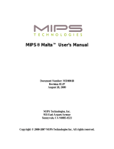
Nomenclature of Module Components
Figure 2.1 or Figure 2.2 shows the names of module components. In the figure, the indicated switch
settings represent factory settings.
Figure 2.1. Nomenclature of Module Components [CPU-CA10(FIT)GY]
Figure 2.2. Nomenclature of Module Components [CPU-CA20(FIT)GY]
5VDC
Vo+
Vo-
FG
CPU-CA10
CONTEC
RUN
STATUS
Gr
oup
ID
0
8
F
7
C
4
B
3
6
E
5
D
A
2
9
1
10M
P
WR
R
x
LIN K
RE SE T
Po
wer/R
X
LINK
FG
STATUS
RU
N
5VDC
Input
RESET
SW
UT
P
P
ort
ERROR
OUT
ERRO
R
OUT
0
4
0
4
6
2
5
1
3
7
U
nit
ID
Group ID
Unit
ID
5VDC
Vo+
Vo-
FG
CONTEC
RUN
STATUS
Group
ID
0
8
F
7
C
4
B
3
6
E
5
D
A
2
9
1
10/100M
AC T
LIN K
R
ESE
T
ACT
LINK
FG
STATUS
R
U
N
Group ID
RESET
SW
UT
P Port
CP
U-C
A2
0
5VD
C
I
np
ut
0
4
0
4
6
2
5
1
3
7
Uni
t
ID
Unit
ID

2. Module Nomenclature and Settings
10
CPU-CA10(FIT)GY, CPU-CA20(FIT)GY
Names and Functions [Common]
Table 2.1. Names and Functions
Name
Function
Settings & Indicator
Status LED
RUN
Refer to Table 2.2. Operating Modes and Status
Indicators
STATUS
LAN LED
LINK
OFF : Not connected
ON : Connected to the LAN
Power/RX [CPU-CA10(FIT)GY]
OFF : Power off
ON : Power on
Flashing: Receiving data
ACT [CPU-CA20(FIT)GY]
OFF : Communication inactive
ON : Communication active
Setting switch Group ID setup
switch: Unit ID
setup switch:
:0 - F
:0 - 7
Group ID : 0 - 8, A *1
0 - 7 : Assist Server connect mode
8 : Stand-alone startup mode
A : Stand-alone startup mode *1
9, B - D : Not used
E is used for V.UP (upgrading) and system recovery
mode.
F : Default initialization mode
Unit ID : 0 - 7 *1
RESET SW
Manual reset
---
ERROR OUT *2
External output contacts, such as Power
OFF
and Link disconnection, for abnormal
conditions
---
UTP port 10BASE-T LAN connect [CPU-
CA10(FIT)GY]
10/100BASE-TX LAN connect
[CPU-CA20(FIT)GY]
---
*1 Group ID "A" (standalone boot mode) can only be used on the CPU-CA20(FIT)GY.
If the Group ID is set to "A", the Unit ID is set in the range 0 - 7Fh by software.
*2 Only on the CPU-CA10(FIT)GY.

2. Module Nomenclature and Settings
CPU-CA10(FIT)GY, CPU-CA20(FIT)GY
11
Operating modes and status indicators [Common]
Table 2.2. Operating Modes and Status Indicators
Operating
mode
Starting
an operation
Condition
of Group ID
Status indicator
RUN
STATUS
Condition
Normal
op. mode
Power ON:
Reset switch ON:
Remote-reset
Set to 0 - 8 or A
ON
OFF
Normal operation
Continuous, alternating
flashing
Resetting
OFF Continuous
flashing
Abnormal conditions
(e.g., memory check error)
ON ON Abnormal conditions
(e.g., start error)
Initialization
mode
(factory
settings)
Power ON:
Reset switch ON:
Remote-reset:
(does not
automatically
return to normal
operating mode)
“F” switch
settings
Continuous
flashing
Continuous
flashing
Initializing
ON
ON
Initialization complete
(To return to normal
operating mode, change
the
GroupID and turn the
power on again or press
the
Reset switch.)
OFF Continuous
flashing
Error during initialization
ON ON Abnormal conditions
(e.g., start error)
Recovery mode
& V.UP mode
Power ON:
Reset switch ON:
Remote-reset:
(does not
automatically
return to normal
operating mode)
“E” switch
settings
Continuous
flashing
OFF
Starting
Continuous
flashing
Continuous
flashing
Writing to firmware
OFF Continuous
flashing
Write error occurred.
ON ON Abnormal conditions
(e.g., start error)
Connectors
Table 2.3. Connectors
Name
Specifications / Function
UTP port Network connection port.
Communication speed: 10Mbps auto-detect [CPU-CA10(FIT)GY]
10/100Mbps auto-detect [CPU-CA20(FIT)GY]
Communication type: Connected as full duplex or half duplex.
ERROR-OUT *1 Output specs: Open collector output by photocoupler insulation
Output ratings: 30VDC(Max.), 10mA(Min.)
Response time: 100µsec(Max.)
Power input
connector
5VDC±5%
2-piece detachable power input connector, FG pin
Dedicated screw-type plug that can be operated from the side
(MCS 5/3-ST-3.5 Phoenix Contact-compliant cable: AWG 28 - 16)
*1
Only on the CPU-CA10(FIT)GY.

2. Module Nomenclature and Settings
12
CPU-CA10(FIT)GY, CPU-CA20(FIT)GY
Error Output [CPU-CA10(FIT)GY only]
Table 2.4. Error Output
Function
Output specs
Error detection
The detection circuit is
normally made; when an
error is detected, the circuit
is
broken.
Output specs:
Open collector output by
photo-coupler insulation
Power supply off,
LINK disconnect,
memory check error,
and other system
errors
Output ratings:
30VDC (Max.), 10mA (Min.)
Response time: 100µsec (Max.)
Reference equivalent circuit [CPU-CA10(FIT)GY only]
Figure 2.3. Reference Equivalent Circuit
Table 2.5. Error Output Pin Assignments
Item
Model
Connector used
S2B-EH (made by J.S.T. Mfg Co.,Ltd.)
Housing
EHR-2 (made by J.S.T. Mfg Co.,Ltd.)
Contact SEH-001T-P0.6 (made by J.S.T. Mfg
Co.,Ltd.)
UTP port pin assignments [Common]
Table 2.6. UTP Port Pin Assignments
CO
M-
2
E
xt
er
na
l
p
ow
er
sup
p
ly
;
3
0V
DC
m
ax
.
-
+
E
rr
or
d
et
ec
ti
o
n
ci
rc
u
it
L
oa
d
E
rr
or
de
te
ct
io
n
o
ut
pu
t
p
in
1
pi
n
2
pin 1
pin
2
Pin No. Signal
1 TD+
2 TD-
3 RD+
4 Not used
5 Not used
6 RD-
7 Not used
8 Not used

2. Module Nomenclature and Settings
CPU-CA10(FIT)GY, CPU-CA20(FIT)GY
13
Setting a Group ID
By setting a Group ID, it is possible to manage the various operating modes (e.g., connecting an I/O
assist server unit, starting the system on a stand-alone basis, or upgrading the system).
A Group ID can be set in a range of 0 - F.
Setup Method
A Group ID can be set by turning the rotary switch on the module face.
To set a Group ID, turn the switch knob.
Figure 2.4. Group ID
0 - 7 : I/O Assist Server Unit connection mode
8 : Stand-alone startup mode
A : Stand-alone startup mode [
CPU-CA20(FIT)GY only
]
9, B - D : Not used
E : System recovery and firmware upgrade mode
F : Initialization mode *1
A Group ID in the 0 - 7 range must be the same as the Group ID for the I/O Assist Server Unit.
When a CPU-CA20(FIT)GY is used with the Group ID set to "A" for standalone boot mode, use
the utility software to set the Unit ID.
*1 About
Initialization mode
Restore the setting of this product to its factory settings. Set the Group ID to "F" and turn the power on. RUN
and STATUS LEDs will start to flash. Once these LEDs stop flashing and grow solid, all settings (IP address
etc.) will be initialized and return to its factory settings after next boot.
Group
ID
Fac
tory
se
tti
ngs:
(
Gro
up ID = 0)
0
1
2
3
4
5
6
7
9
A
B
C
D
E
F
8
CAUTI
ON
/