Page is loading ...

R2080, R2100, R2180
Compact Controller 96 x 96 mm
3-349-219-15
5/4.19
Operating Instructions

Contents Page Page
2 GMC-I Messtechnik GmbH
Safety Features and Precautions . . . . . . . . . . . . . . . . . 3
Maintenance . . . . . . . . . . . . . . . . . . . . . . . . . . . . . . . 3
Repair and Replacement Parts Service . . . . . . . . . . . . 4
Product support . . . . . . . . . . . . . . . . . . . . . . . . . . . . . 4
Identification of Controller R2080 . . . . . . . . . . . . . . . . 5
Identification of Controller R2100 . . . . . . . . . . . . . . . . 6
Identication of Controller R2180 . . . . . . . . . . . . . . . . . 7
Mechanical Installation / Preparation . . . . . . . . . . . . . 8
Differences between R2080/R2100/R2180 and
GTR0208/GTR0210/GTR0218 . . . . . . . . . . . . . . . . . . 9
Connection R2080 . . . . . . . . . . . . . . . . . . . . . . . . . 10
Connection R2100 . . . . . . . . . . . . . . . . . . . . . . . . . 11
Connection R2180 . . . . . . . . . . . . . . . . . . . . . . . . . 12
Electrical Connection . . . . . . . . . . . . . . . . . . . . . . . . 13
Performance After Activating Auxiliary Voltage . . . . . . 13
Display – Setpoint Selection – Operation . . . . . . . . . 14
Operating Flowchart . . . . . . . . . . . . . . . . . . . . . . . . . 15
Parameters Configuration . . . . . . . . . . . . . . . . . . . . . 16
Limit Value Monitoring . . . . . . . . . . . . . . . . . . . . . . . 17
Adjusting Control Performance – Manual Self-Tuning 18
Self-Tuning . . . . . . . . . . . . . . . . . . . . . . . . . . . . . . . 21
Alarms . . . . . . . . . . . . . . . . . . . . . . . . . . . . . . . . . . 22
Error Messages . . . . . . . . . . . . . . . . . . . . . . . . . . . . 22
Setpoint Ramps . . . . . . . . . . . . . . . . . . . . . . . . . . . . 24
Balancing . . . . . . . . . . . . . . . . . . . . . . . . . . . . . . . . 24
Configuration . . . . . . . . . . . . . . . . . . . . . . . . . . . . . . 25
Saving and Loading Device Settings . . . . . . . . . . . . . 28
Exchange of Setpoint with Binary Input . . . . . . . . . . . 29
Manual Operation with Binary Input . . . . . . . . . . . . . . 29
PWR Out Offset with Binary Input . . . . . . . . . . . . . . . .29
Heating Current Monitoring . . . . . . . . . . . . . . . . . . . .30
Heating Circuit Monitoring . . . . . . . . . . . . . . . . . . . . .30
Technical Data . . . . . . . . . . . . . . . . . . . . . . . . . . .31
Meanings of symbols on the instrument
Indicates EC conformity
Continuous doubled or
reinforced insulation
Warning concerning a source of danger
Attention: observe documentation!
Functional earth terminal,
earthing for functional purposes only
(no safety function)

GMC-I Messtechnik GmbH 3
Safety Features and Precautions
The R2XX0 controllers are manufactured and tested in accordance with safety regulations IEC 61010-1 /
DIN EN 61010-1 / VDE 0411-1.
If used for its intended purpose, safety of the user and of the device is assured.
Read the operating instructions completely and carefully before using the device, and follow all instructions included
therein. The operating instructions should be made available to all users.
Observe the following safety precautions:
– The device may only be connected to electrical systems which comply with the specified nominal range of
use (see circuit diagram and serial plate), and which are protected with a fuse or circuit breaker with a
maximum nominal current rating of 16 A.
– The installation must include a switch or a circuit breaker which serves as a disconnecting device.
The controller may not be used:
– If visible damage is apparent
– If it no longer functions flawlessly
– After lengthy periods of storage under unfavorable conditions (e.g. humidity, dust, temperature)
In such cases the device must be removed from service and secured against any possible inadvertent use.
Maintenance
Housing
No special maintenance is required for the housing. Keep outside surfaces clean. Use a slightly dampened cloth
for cleaning. Avoid the use of solvents, cleansers and abrasives.
Repair and Parts Replacement
Repairs and the replacement of parts conducted at a live open instrument may only be carried out by trained
personnel who are familiar with the dangers involved.

4 GMC-I Messtechnik GmbH
Repair and Replacement Parts Service
When you need service, please contact:
GMC-I Service GmbH
Service Center
Beuthener Str. 41
90471 Nürnberg, Germany
Phone: +49 911 817718-0
Fax: +49 911 817718-253
E-Mail: [email protected]
This address is only valid in Germany.
Please contact our representatives or subsidiaries for service in other countries.
Product support
When you need support, please contact:
GMC-I Messtechnik GmbH
Product Support Hotline
Phone: +49 911 8602-500
Fax: +49 911 8602-340
E-Mail [email protected]

GMC-I Messtechnik GmbH 5
Identification of Controller R2080
Features A3, A13, C23 and E3 of controller GTR0208
cannot be replaced.
Feature B2 is not compatible with GTR0208.
Auxiliary voltage is generally AC 110 230 V.
A switch to deactivate the control outputs is always
available (see feature F1 of controller GTR0208).
Generally, the actual value and the setpoint value and/
or heating current are indicated.
As a rule, setpoint limiting is available.
Feature
Designation
Electronic PDPI controller R2080
Controller types
2-step controller medium time response A01
2-step controller with limit contact medium time response A02
3-step controller medium time response A04
2-step controller short time response A11
2-step controller with limit contact short time response A12
3-step controller short time response A14
without feedback with 1 limit contact A21
without feedback with 2 limit contacts A22
Measuring ranges
Thermocouple type L Fe-CuNi 0 200 CC01
0 400 CC02
0 600 CC03
type J Fe-CuNi 0 200 CC04
0 400 CC05
0 600 CC06
0 800 CC07
type K NiCr-Ni 0 400 CC08
0 600 CC09
0 800 CC10
0 1200 CC11
type R Pt13Rh-Pt 0 1600 CC12
type S Pt10Rh-Pt 0 1600 CC13
Resistance thermometer Pt100 0 100 CC20
0 200 CC21
0 400 CC22
–100 100 CC24
–100 200 CC25
Output type 1
st
switching point
Relay D1
Transistor D2

6 GMC-I Messtechnik GmbH
Identification of Controller R2100
Features C23 and E5 of controller GTR0210 cannot be
replaced.
Auxiliary voltage is generally AC 110 230 V.
A switch to deactivate the control outputs and a
switching facility for the display is always available
(see features F1 and F2 of controller GTR0210).
Feature
Designation
Electronic PDPI controller R2100
Controller types
2-step controller A1
3-step controller A2
Time response
medium XB0
short XB1
long XB2
Measuring range
Thermocouple type L Fe-CuNi 0 400 CC01
0 800 CC02
type J Fe-CuNi 0 400 CC03
type K NiCr-Ni 0 400 CC05
0 600 CC06
0 800 CC07
0 1200 CC08
type R Pt13Rh-Pt 0 1600 CC09
type S Pt10Rh-Pt 0 1600 CC10
Resistance thermometer Pt100 0 100 CC20
0 200 CC21
0 400 CC22
–100 200 CC24
Direct current 0 5 mA C30
0 20 mA C31
0 20 mA, display 0.00 2.00 C32
Output type 1
st
switching point
Relay D1
Transistor D2
Limit contact
none G0
MIN / MAX G1
Rupture protection
direct action XH0
reverse action XH1

GMC-I Messtechnik GmbH 7
Identication of Controller R2180
Features C35, C42, C55, C62 and E1 of controller
GTR0218 cannot be replaced.
Auxiliary voltage is generally AC 110 230 V.
A switch to deactivate the control outputs is always
available (see feature F1 of controller GTR0218).
Feature
Designation
Electronic PDPI controller R2180
Controller types
2-step controller A1
3-step controller A2
2-step controller with MAX limit contact A3
2-step controller with MAX / MIN limit contact A4
Time response
short B1
medium B2
long B3
Measuring range
Thermocouple Ctype L Fe-CuNi 0 199 CC01
0 399 CC02
0 599 CC03
type J Fe-CuNi 0 199 CC04
0 399 CC05
0 599 CC06
32 392 FC13
32 752 FC14
32 1112 FC15
type K NiCr-Ni 0 399 CC07
0 599 CC08
0 799 CC09
0 1200 CC10
32 752 FC16
32 1112 FC17
32 1472 FC18
32 2192 FC19
type R Pt13Rh-Pt 0 1600 CC11
32 2912 FC20
type S Pt10Rh-Pt 0 1600
CC12
32 2912 FC21
Resistance thermometer Pt100 –99,9 +99,9 CC30
(2-wire connection) –99,9 +199,9 CC31
0 +99,9 CC32
0 +199,9 CC33
0 +399,9 CC34
–148 +212 FC37
–148 +392 FC38
32 212 FC39
32 392 FC40
32 752 FC41
Resistance thermometer Pt100 –99,9 +99,9 CC50
(3-wire connection) –99,9 +199,9 CC51
0 +99,9 CC52
0 +199,9 CC53
0 +399,9 CC54
–148 +212 FC57
–148 +392 FC58
32 212 FC59
32 392 FC60
32 752 FC61
Output type 1
st
switching point
Relay D1
Transistor D2
Feature
Designation

8 GMC-I Messtechnik GmbH
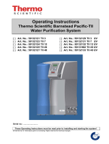
Mechanical Installation / Preparation
The RXX0 controller is intended for installa-
tion to a control panel. The installation lo-
cation should be vibration-free to the great-
est possible extent. Aggressive vapors
shorten the service life of the controller.
Requirements set forth in VDE 0100 must
be observed during the performance of all
work. Work on the device may only be car-
ried out by trained personnel who are fa-
miliar with the dangers involved.
Set the housing into the panel cutout from
the front, and secure it from behind at the
left and right-hand sides with the two in-
cluded screw clamps.
Push the screw clamps first all the way up
to the limit stop in direction 1 and subse-
quently in direction 2 for this purpose.
Typical tightening torque amounts to
10 Ncm, and a value of 20 Ncm should not
be exceeded.
In general, unobstructed air circulation
must be assured when one or several de-
vices are installed. The ambient tempera-
ture underneath the devices may not ex-
ceed 50 C.
5
96
96
50
R2080, R2180 and R2100 G0
R2100 G1 only
92
+0,8
92
+0,8
Panel cutout
1
2
1
2
70
5

GMC-I Messtechnik GmbH 9
Differences between R2080/R2100/R2180 and GTR0208/GTR0210/GTR0218
Controllers R2080, R2100 and R2180 do not supersede analog devices GTR0208, GTR0210 and GTR0218 in
a fully compatible manner. Please note the following deviations:
Temperature sensor Pt100
As a rule, controllers R2080, R2100 and R2180 are provided with a 3-wire-connection.
Consequently, for Pt100 (but not in the case of a thermocouple), terminals 18-19 at controllers R2080 / R2100
or terminals 12-13 at controller R2180 must be shunted.
Sensor rupture protection
Controllers R2080, R2100 and R2180 are able to detect a broken sensor and/or polarity reversal of the sensor,
whereupon the actuating outputs are deactivated and an alarm is triggered at the same time.
If the actuating outputs are to assume a certain status, it must be set with parameter Y SE.
Protective conductor connection
According to EMC requirements controllers R2080, R2100 and R2180 must be provided with a protective con-
ductor connection.
Cooling output
In the case of 3-step controllers R2080 / R2180, the 2
nd
switching point cannot be used as an NC contact.
Limit contact
In the case of controller types R2080 / R2180 with limit contact, the configuration of the R2080 / R2180 must
be changed from CnF1 = 0xx0 to 0xx4 while using the break contact (reverse action principle). Switching point
distance w can only be set as a relative MAX alarm to a value above zero for the R2080 / R2180.
Heating current display / monitoring
Heating current transformer GTY 2570 127 R0x can no longer be used in connection with R2080.
Instead, 3-input and/or 4-input current transformers GTZ 4121 must be fitted for acquiring heating current.
This offers the additional feature of not only indicating the heating current but also monitoring antivalence pro-
vided the R2080 has been appropriately set. In this case, an alarm is triggered if current is too low while heating
is activated or if current is not „off“ while heating is deactivated (see also page 30).
RC elements
In contrast to GTR0210, no RC elements for spark suppression have been fitted in controllers R2080, R2100
and R2180. It is therefore recommended retrofitting the controlled actuators (contactors, solenoid valves, etc.)
with the associated RC elements.

10 GMC-I Messtechnik GmbH
Connection R2080
Auxiliary
Voltage
Binary
Input
Heating
Current Transf.
19 18 17
Sensor
86 85 1 2/3
12 11
Outputs
A1, A11, A21
additionally with
A2, A4,
D1
42 41
D2
Relay Output
Transistor Output
110 ...
230 V
NL
I
14 15
Relay Output
II
I
–+
27 26
A12, A14, A22

GMC-I Messtechnik GmbH 11
Connection R2100
Auxiliary
Voltage
62
Binary
Input
Heating
Current Transf.
63 61 60
Alarms
19 18 17
Sensor
C01 ... C24
C30, C31
G1
86 85 1 2/3
12 11
Outputs
A1
additionally with
A2
D1
42 41
D2
Relay Output
Transistor Output
110 ...
230 V
NL
A1
A2
20 mA
10 V
I
8 9
Relay Output
II
I
–+
16 15

12 GMC-I Messtechnik GmbH
Connection R2180
Auxiliary
Voltage
Binary
Input
Heating
Current Transf.
13 12 11
Sensor
86 85 N L
48 47
Outputs
A1
additionally with
A2, A3, A4
D1
82 81
D2
Relay Output
Transistor Output
110 ...
230 V
NL
I
57 58
Relay Output
II
I
–+
16 15

GMC-I Messtechnik GmbH 13
Electrical Connection
Connectors: Screw terminals for wire with a cross section of 1.5 square mm or
two-core wire-end ferrules with a cross-section of 2 x 0.75 square mm
Tighten screws with a manual screwdriver only! Tightening torque for all screw terminals: max. 0.6 Nm
EN 55022 requires the following warning as regards electromagnetic compatibility:
Performance After Activating Auxiliary Voltage
Warning
This is a class A device. It may cause radio interference in residential surroundings. If this is the
case, the operator may be required to implement appropriate corrective measures.
U/M Software Version
Current Configuration
LED Segment Test
approx. 2 s
approx. 1.5 s
CnF1
Actual Value
Setpoint or oFF
approx. 1.5 s
Current
Configuration
Hardware Designation
G Designation
CnF2

14 GMC-I Messtechnik GmbH
Display – Setpoint Selection – Operation
W2
A2
A1
II
I
R2XX0
GOSSEN METRAWATT
Actual value
Setpoint value / PWR (pulse width ratio)
Setpoint 2 active
Off
Switching output I active
Switching output II active
Alarm(s) active
Press and hold:
Press briefly:
Shift setpoint value PWR
Press and hold:
Changeover to parameter level
(see operating flowchart)
Up and down scrolling keys for setpoint value
selection (and parameter setting)
The value is changed directly. After 2,5 s or after
pressing key , the value is stored to memory and
becomes active.
This is acknowledged by a brief blackout of the display.
Switchover Off automatic operation

GMC-I Messtechnik GmbH 15
Operating Flowchart
I
II
A1
A2
W2
Act. val.
Automatic Operation
PARAMETER LEVEL
Off
OPERATING LEVEL
CONFIGURATION
Press key briefly
Press and hold key
until the display is switched
Press and hold both keys,
until display is switched
(page 16)
(page 25)
Only appears when heating
current monitoring is activated.
Setpoint can only
be selected here.
I
II
A1
A2
W2
Act. val.
Setpoint
I
II
A1
A2
W2
Act. val.
Heat. curr.
I
II
A1
A2
W2
Act. val.
PWR
I
II
A1
A2
W2
Param. value
I
II
A1
A2
W2
Param. value
I
II
A1
A2
W2
I
II
A1
A2
W2
Off
– no alarm function
– no error signalling
– The actuating outputs are inactive
unless keys are pressed.
– By pressing key /
switching output I („heating“) /
II („cooling“) is directly controlled.
I
II
A1
A2
W2
Act. val.

16 GMC-I Messtechnik GmbH
Parameters Configuration
X1 = lower range limit, X2 = upper range limit,
MBU = X2 – X1
. These values refer to the configured sensor type
(see Configuration page 25), not to the C Designation.
Parameter Display Range Default Comment
Upper limit value for relay A1
oFF, 1 ... MBU
oFF, X1 ... X2
oFF / *
oFF / *
Relative (= default config.)
Absolute
Lower limit value for relay A1
Upper limit value for relay A2
Lower limit value for relay A2
Setpoint 2 SP L ... SP H X1
Ramp for rising setpoints oFF, 1 ... MBU pro min oFF
Ramp for falling setpoints oFF, 1 ... MBU pro min oFF
Heating current setpoint
(see Balancing)
Auto, oFF, 0.1 ... A H oFF
Not with step-action
controllers
1)
Proportional band heating 0.1 ... 999.9 % 10.0 / *
Proportional band cooling 0.1 ... 999.9 % 10.0 / * Only with 3-step controllers
2)
Dead band 0 ... MBU 0 Not with 2-step controllers
3)
Path delay time 0 ... 9999 s 100 / *
Read-out cycle time 0.5 ... 600.0 s 10.0 / *
Motor run-time
5 ... 5000 s 60
Only with step-action
controllers
4)
Switching hysteresis
0 ... 1,5%MBU 0,5%MBU / *
For limit value monitoring and
limit transducers
Maximum setpoint SP L ... X2 X2 / *
Minimum setpoint X1 ... SP H X1 / *
Maximum PWR –100 ... 100 % 100
Actual value correction
(see Balancing)
(Auto), –MBU/4 ... +MBU / 4 0 / *
Only with designations
C01 ... C24

GMC-I Messtechnik GmbH 17
Parameters Pb 1 through yse are disabled for the operator during self-tuning.
Limit Value Monitoring
Actuation suppression: Alarm suppression remains inactive during actuation (configuration digit “alarms 1 and 2”)
until temperature has exceeded the lower limit value for the first time. During cooling, suppression is active until
temperature has fallen below the upper limit value for the first time. Suppression is active when auxiliary power
is activated, if the current setpoint is changed or setpoint 2 is activated, or if switching takes place from off to
automatic operation.
Decimal point position 9999, 9999, 9999, 9999 9999 / *
only for designations C30, C31Upper range limit, standard signal rn L ... 9999 100 / *
Lower range limit, standard signal –1500 ... rnH 0
Upper range limit, heating current
(see Balancing)
1.0 ... 99.9 A 42,7
not with step-action
controllers
1)
PWR for actuator mode, or for PWR
out offset
–100 ... 100 % 0
Sensor error PWR –100 ... 100 % 0 / *
1)
only where:“controller sort” configuration digit 6
2)
only where:“controller sort” configuration digit = 4 or 5
3)
only where:“controller sort” configuration digit = 0, 4, 5 or 6
4)
only where:“controller sort” configuration digit = 6
* the values have been preset to match the order features.
Alarm Relay n, NO Contact
Alarm Relay n, NC Contact
n = 1, 2
ALnL ALnH
Relative Limit Values
ALnL ALnH
Absolute Limit Values
Parameter Display Range Default Comment
Actual ValueSetpoint
Hysteresis (HYSt)

18 GMC-I Messtechnik GmbH
Adjusting Control Performance – Manual Self-Tuning
Parameters Pb 1, Pb 11, tu and tc are determined by means of manual self-tuning in order to maintain opti-
mized controller dynamics. An actuation test or an oscillation test is performed to this end.
Preparation
– Complete configuration (page 25) and parameters configuration (page 16) must first be entered for use of the
controller.
– The actuators should be deactivated with the off function (page 15).
–A recorder must be connected to the sensor and adjusted appropriately to prevailing circuit dynamics and
the setpoint.
– For 3-step controllers, on and off-time must be recorded for switching output I (e.g. with an additional
recorder channel or a stopwatch).
– Configure as limit transducer (controller sort = 0) (see page 25).
– Set read-out cycle time to the minimum value: tc = 0.5.
– Deactivate PWR limiting. YH = 100.
– Reduce (or increase) the setpoint so that overshooting and undershooting do not cause any impermissible
values.
Performing the Actuation Test
– dbnd = MRS Setting for 3-step controller (switching output II may not be triggered)
dbnd = 0 Setting for step-action controllers (switching output II must be triggered)
– Start the recorder.
– Activate the actuators with automatic operation.
– Record two overshoots and two undershoots.
The actuation test is now complete for 2-step and step-action controllers.
Continue as follows for 3-step controllers:
–Set dbnd to 0 in order to cause further overshooting with active switching output II. Record two overshoots
and two undershoots.
Record on-time T
I
and off-time T
II
at switching output I or the continuous output for the last oscillation.

GMC-I Messtechnik GmbH 19
Evaluating the Actuation Test
– Apply a tangent to the curve at the intersection of the actual value and the setpoint, or at the cut-off point of
the output.
– Measure time t.
– Measure oscillation amplitude x
ss
, or overshooting for step-action controllers x.
1)
When controlling contactors, tc should be adequately increased.
MRS = Measuring range span of the configured sensor type (compare Configuration, see page 25), not the
measuring range according to C Designation
Performing the Oscillation Test
If an actuation test is not possible, for example if neighboring control loops influence the actual value too greatly,
if switching output II must be active in order to maintain the actual value (cooling operating point), or if optimiza-
tion is required directly to the setpoint for any given reason, control parameters can be determined by means of
sustained oscillation. However, calculated values for tu may be very inaccurate in this case under certain cir-
cumstances.
– Same preparation as for actuation test. The test can be performed without a recorder if the actual value is
observed at the display, and if times are measured with a stopwatch.
Parameter Parameter Values
2-step controller 3-step controller Step-action controller
tu 1.5
t t – (tY / 4)
tc tu / 12
1)
tY / 100
Pb 1 (x
ss
/ MRS) 100 % (x / MRS) 50 %
Pb 11 — Pb 1
(T
I
/ T
II
)—
P
t
x
x
ss
T
I
T
II
dbnd = 0dbnd = MRS
(3-step controller only)

20 GMC-I Messtechnik GmbH
– dbnd = 0 Setting for 3-step and step-action controllers
– Activate the actuators with automatic operation, and start the recorder if applicable. Record several
oscillations until they become uniform in size.
– Measure oscillation amplitude x
ss
.
– Record on-time T
I
and off-time T
II
at switching output I for the oscillations.
Evaluating the Oscillation Test
1)
If either T
I
or T
II
is significantly greater than the other, value tu is too large.
2)
When controlling contactors, tc should be adequately increased.
Correction for step-action controllers in the event that T
I
or T
II
is smaller than tY:
tY
tY tY tY
Multiply Pb 1 by if T
I
is smaller, or by if T
II
is smaller.
T
I
T
I
T
II
T
II
The value for tu is very inaccurate in this case. It should be optimized in the closed loop control mode.
Closed Loop Control Mode
The closed loop control mode is started after self-tuning has been completed:
– Configure the desired control algorithm with controller sort.
–Adjust the setpoint to the required value.
– The dead band can be increased from dbnd = 0 for 3-step and step-action controllers if control of switching
output I and II changes too rapidly, for example due to an unsteady actual value.
Parameter Values
Parameter 2-step controller 3-step controller Step-action controller
tu
1)
0.3 (T
I
+ T
II
)0.2 (T
I
+ T
II
– 2tY)
tc tu / 12
2)
tY / 100
Pb 1 x
ss
100 %
MRS
x
ss
T
II
100 %
MRS (T
I
+ T
II
)
x
ss
50 %
MRS
Pb 11 — Pb 1
(T
I
/ T
II
)—
T
I
T
II
x
ss
/