Page is loading ...

R2900
Compact Controller, 96 x 96 mm
3-349-203-15
6/8.09
Operating Instructions

Contents Page Page
2 GMC-I Messtechnik GmbH
Safety Features and Precautions . . . . . . . . . . . . . . . . 3
Maintenance . . . . . . . . . . . . . . . . . . . . . . . . . . . . . . . 3
Repair and Replacement Parts Service . . . . . . . . . . . . 4
Product Support . . . . . . . . . . . . . . . . . . . . . . . . . . . . 4
Device Identification . . . . . . . . . . . . . . . . . . . . . . . . . 5
Data Interface . . . . . . . . . . . . . . . . . . . . . . . . . . . . . . 6
Mechanical Installation / Preparation . . . . . . . . . . . . . 6
Electrical Connection . . . . . . . . . . . . . . . . . . . . . . . . . 8
Performance After Activating Auxiliary Voltage . . . . . 10
Operation . . . . . . . . . . . . . . . . . . . . . . . . . . . . . . . . 11
Operating Flowchart,
“Discontinuous-Action Controller” . . . . . . . . . . . . . . 12
Operating Flowchart, “Discontinuous-Action Controller”
with Differential Control . . . . . . . . . . . . . . . . . . . . . . 13
Operating Flowchart,
“Continuous-Action and Step-Action Controllers” . . . 14
Operating Flowchart, “Cont.-Action and
Step-Action Controller” with Diff. Control . . . . . . . . . 15
Off / Manual Operation . . . . . . . . . . . . . . . . . . . . . . 16
Manual Operation with Binary Input . . . . . . . . . . . . . 17
PWR Out Offset with Binary Input . . . . . . . . . . . . . . . 17
Configuration . . . . . . . . . . . . . . . . . . . . . . . . . . . . . 18
Saving and Loading Device Settings: . . . . . . . . . . . . 21
Differential Controller . . . . . . . . . . . . . . . . . . . . . . . . 21
Slave Controller . . . . . . . . . . . . . . . . . . . . . . . . . . . . 21
Controller Sorts . . . . . . . . . . . . . . . . . . . . . . . . . . . . 22
Configuration of the Controller with Continuous Output
(desig. A7 and A8) . . . . . . . . . . . . . . . . . . . . . . . . . 23
Parameters Configuration . . . . . . . . . . . . . . . . . . . . 24
Balancing . . . . . . . . . . . . . . . . . . . . . . . . . . . . . . . . 26
Self-Tuning . . . . . . . . . . . . . . . . . . . . . . . . . . . . . . .27
Manual Self-Tuning . . . . . . . . . . . . . . . . . . . . . . . . .28
Setpoint Ramps . . . . . . . . . . . . . . . . . . . . . . . . . . . .31
Heating Current Monitoring . . . . . . . . . . . . . . . . . . .32
Heating Circuit Monitoring . . . . . . . . . . . . . . . . . . . .32
Limit Value Monitoring . . . . . . . . . . . . . . . . . . . . . . .33
Alarms . . . . . . . . . . . . . . . . . . . . . . . . . . . . . . . . . .33
Error Messages . . . . . . . . . . . . . . . . . . . . . . . . . . . .34
Technical Data . . . . . . . . . . . . . . . . . . . . . . . . . .36
Meanings of symbols on the instrument
Continuous doubled or
Warning concerning a source of danger
Indicates EC conformity
reinforced insulation
Attention: observe documentation!
Functional earth terminal,
earthing for functional purposes only
(no safety function)
The device may not be disposed of with the
trash. Further information regarding the
WEEE mark can be accessed on the Internet
at www.gossenmetrawatt.com under the
search term WEEE

GMC-I Messtechnik GmbH 3
Safety Features and Precautions
The R2900 controller is manufactured and tested in accordance with safety regulations IEC 61010-1 /
DIN EN 61010-1 / VDE 0411-1.
If used for its intended purpose, safety of the user and of the device is assured.
Read the operating instructions completely and carefully before using the device, and follow all instructions included
therein. The operating instructions should be made available to all users.
Observe the following safety precautions:
– The device may only be connected to electrical systems which comply with the specified nominal range of
use (see circuit diagram and serial plate), and which are protected with a fuse or circuit breaker with a
maximum nominal current rating of 16 A.
– The installation must include a switch or a circuit breaker which serves as a disconnecting device.
The controller may not be used:
– If visible damage is apparent
– If it no longer functions flawlessly
– After lengthy periods of storage under unfavorable conditions (e.g. humidity, dust, temperature)
In such cases the device must be removed from service and secured against any possible inadvertent use.
Maintenance
Housing
No special maintenance is required for the housing. Keep outside surfaces clean. Use a slightly dampened
cloth for cleaning. Avoid the use of solvents, cleansers and abrasives.
Repair and Parts Replacement
Repairs and the replacement of parts conducted at a live open instrument may only be carried out by trained
personnel who are familiar with the dangers involved.

4 GMC-I Messtechnik GmbH
Repair and Replacement Parts Service
When you need service, please contact:
GMC-I Service GmbH
Service-Center
Thomas-Mann-Strasse 20
90471 Nürnberg • Germany
Phone +49 911 817718-0
Fax +49 911 817718-253
E-Mail [email protected]
This address is only valid in Germany.
Please contact our representatives or subsidiaries for service in other countries.
Product Support
When you need support, please contact:
GMC-I Messtechnik GmbH
Product Support Hotline
Phone +49 911 8602-500
Fax +49 911 8602-340
E-Mail [email protected]

GMC-I Messtechnik GmbH 5
Device Identification
Electronic controller with self-tuning and 2
nd
setpoint, front panel dimensions: 96 x 96 mm
R2900
Controller Types
2 / 3-step controller with heating current monitoring / step-action controller 2 transistor outputs
2 / 3-step controller with heating current monitoring 1
st
switching point: transistor output
2
nd
switching point: relay output
2 / 3-step controller with heating current monitoring 1
st
switching point: relay output
2
nd
switching point: transistor output
2 / 3-step controller with heating current monitoring / step-action controller 2 relay outputs
Step-action controller with repeater / 3-step controller 2 transistor outputs
Step-action controller with repeater / 3-step controller 2 relay outputs
Cont.-action contr. / step-action contr. / 3-step contr. w. heat current monit. 1 continuous output and 2 transistor outputs
Cont.-action contr. / step-action contr. / 3-step contr. w. heat current monit. 1 continuous output and 2 relay outputs
A1
A2
A3
A4
A5
A6
A7
A8
Measuring Ranges
Input Thermocouple, configurable Type J, L –18 ... 850C / 0 ... 1562F
Type K –18 ... 1200C / 0 ... 2192F
Type S, R –18 ... 1770C / 0 ... 3218F
Type B 0 ... 1820 C / 32 ... 3308F (especially 600C)
Type N –18 ... 1300 C / 0 ... 2372F
Resistance thermometer Pt 100 – 100 ... 500C / –148 ... 932F
B1
Input Standard signal, configurable 0 / 2
... 10 V or 0 / 4 ... 20 mA B2
Both measurement inputs can be mutually
configured as per B1 for differential controller.B3
1
st
measurement input same as B1, 2
nd
same as B2, can be configured for slave controller B4
Auxiliary Voltage AC 110 ... 230 V C1
Limit Contacts None
Two 2 relay outputs
D0
D1
Data Interface None
RS 485 or RS 232 (internally selectable)
F0
F1
Configuration Default settings
Configure per customer requirements
K0
K9
Operating German / English
Instructions French / Italian
None
L0
L1
L2

6 GMC-I Messtechnik GmbH
Data Interface
Refer to operating instructions 3-349-204-15 for detailed information regarding the data interface.
Mechanical Installation / Preparation
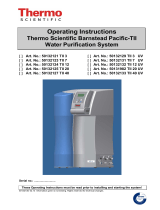
Figure 1, Housing Dimensions and Panel Cutout
The R2900 controller is intended for installation to a control panel.
The installation location should be vibration-free to the greatest
possible extent. Aggressive vapors shorten the service life of the
controller. Requirements set forth in VDE 0100 must be observed
during the performance of all work. Work on the device may only
be carried out by trained personnel who are familiar with the dan-
gers involved.
Set the housing into the panel cutout from the front, and secure it
from behind at the left and right-hand sides with the two included
screw clamps. Typical tightening torque amounts to 10 Ncm, and
a value of 20 Ncm should not be exceeded.
In general, unobstructed air circulation must be assured when one
or several devices are installed. The ambient temperature under-
neath the devices may not exceed 50 C.
5
96
96
50
570
Variants
A1 ... A6, D0, F0
Variant A7, A8 or D1, or
F1
92
+0,8
92
+0.8
Panel Cutout

GMC-I Messtechnik GmbH 7
Figure 2, Securing the Housing
Securing the two screw clamps at the
right and left-hand sides of the housing:
– Push in direction 1 all the way up to the limit stop
– Push in direction 2 all the way up to the limit stop
1
2

8 GMC-I Messtechnik GmbH
Electrical Connection
Auxi-
liary
7 8 9
110 ...
230 V
NL
voltage
Binary-
input
5 6
11 12 13
Sensor 1
B1,B3,B4
B2
20 mA
10 V
14 15 16
Sensor 2
B3
B4
20 mA
10 V
21 22 23 24
Alarms
D1
A1
A2
1 2
Outputs
A3, A4, A6, A8
1 2
Switching Outputs
Transistor Output
I
3 4
Switching Outputs
II
I
–+
A2, A4, A6, A8
3 4
Transistor Output
II
–+
A1, A2, A5, A7 A1, A3, A5, A7
25 26 27 28 29
F1
Continuous Output
RS-232 / RS-485
A7, A8
CBA
GND TxD RxD
–+
10V/20mA
17 18 19
Repeater
A5, A6
Current Transformer
A1,A2,A3
A4,A7,A8
18 19

GMC-I Messtechnik GmbH 9
EN 55022 requires the following warning as regards electromagnetic compatibility:
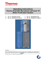
Figure 3, Connector Terminal Positions
Warning
This is a class A device. It may cause radio interference in residential surroundings. If this is the
case, the operator may be required to implement appropriate corrective measures.
Connectors: Screw terminals for wire with a cross section of 1.5 square mm or
two-core wire-end ferrules with a cross-section of 2 x 0.75 square mm
Tighten screws with a manual screwdriver only! Tightening torque for all screw termi-
nals: max. 0.6 Nm

10 GMC-I Messtechnik GmbH
Performance After Activating Auxiliary Voltage
U/M Software Version
Current Configuration
LED Segment Test
approx. 2 s
approx. 1.5 s
CnF1
Actual Value
Setpoint or oFF
approx. 1.5 s
Current
Configuration
B Designation
D Designation
CnF2
A Designation

GMC-I Messtechnik GmbH 11
Operation
Figure 4, Controls
Value Selection
The selected value can be changed using the up and down scrolling keys.
The selected value is saved to memory and becomes active after 2.5 seconds, or after pressing the key.
The display goes dark briefly to indicate activation of the selected value.
W2
A2
A1
II
I
R2900GOSSEN METRAWATT
Actual value or
Setpoint / heating current /
Setpoint 2 active
Off / manual operation
value or parameter designation
Switching output I
Switching output II
Alarm(s) active
Select: off / manual
automatic operation
Shift displays, levels and values
(see operating flow chart)
Up and down scrolling keys for value selection
parameter value
active
active
manipulating factor / 2nd actual

12 GMC-I Messtechnik GmbH
Operating Flowchart, “Discontinuous-Action Controller”
I
II
A1
A2
W2
Actual
Automatic Operation
PARAMETER LEVEL
Off
OPERATING LEVEL
CONFIGURATION
Press key briefly.
Press and hold key until
the display is switched.
Press and hold both keys until
the display is switched.
(page 24)
(page 18)
Only appears when heating current
monitoring is activated.
Setpoint can only be
selected here for
Extended oper-
ating level when
configured as
differential con-
troller see page
13
fixed setpoint controllers.
I
II
A1
A2
W2
Actual
Setpoint
I
II
A1
A2
W2
Actual
I Heat
I
II
A1
A2
W2
Actual
M. Factor
I
II
A1
A2
W2
Param. Value
I
II
A1
A2
W2
Param. Value
I
II
A1
A2
W2
I
II
A1
A2
W2

GMC-I Messtechnik GmbH 13
Operating Flowchart, “Discontinuous-Action Controller” with Differential Control
I
II
A1
A2
W2
Actual Diff.
Automatic Operation
PARAMETER LEVEL
Off
OPERATING LEVEL
CONFIGURATION
Press key briefly.
Press and hold key until
the display is switched.
Press and hold both keys until
the display is switched.
(page 24)
(page 18)
Only appears when heating
current monitoring is activated.
Differential setpoint can
only be selected here.
I
II
A1
A2
W2
Diff. Set-
I
II
A1
A2
W2
I Heat
I
II
A1
A2
W2
M. Factor
I
II
A1
A2
W2
Param. Value
I
II
A1
A2
W2
Parameter Value
I
II
A1
A2
W2
I
II
A1
A2
W2
I
II
A1
A2
W2
Act. Val. 1
Actual Diff.
Act. Val. 2
Actual Diff.
Actual Diff.

14 GMC-I Messtechnik GmbH
Operating Flowchart, “Continuous-Action and Step-Action Controllers”
I
II
A1
A2
W2
Act. Val.
Automatic Operation
PARAMETER LEVEL
Manual Operation
OPERATING LEVEL
CONFIGURATION
Press key briefly.
Press and hold key until
the display is switched.
Press and hold both keys until
the display is switched.
(page 24)
(page 18)
Setpoint can only be selected here
for fixed setpoint controllers.
Extended operating level when
configured as differential con-
troller, see page 15
I
II
A1
A2
W2
Act. Val.
Setpoint
I
II
A1
A2
W2
Act. Val.
M. Factor
I
II
A1
A2
W2
Param. Value
I
II
A1
A2
W2
Param. Value
I
II
A1
A2
W2
I
II
A1
A2
W2
Only for step-action
controllers with
M. Factor
designation A5, A6

GMC-I Messtechnik GmbH 15
Operating Flowchart, “Cont.-Action and Step-Action Controller” with Diff. Control
I
II
A1
A2
W2
Actual Diff.
Automatic Operation
PARAMETER LEVEL
Manual Operation
OPERATING LEVEL
CONFIGURATION
Press key briefly.
Press and hold key until
the display is switched.
Press and hold both keys until
the display is switched.
(page 24)
(page 18)
Differential setpoint can only
be selected here.
I
II
A1
A2
W2
Diff. Set-
I
II
A1
A2
W2
I
II
A1
A2
W2
Actual Diff.
M. Factor
I
II
A1
A2
W2
Param. Value
I
II
A1
A2
W2
Param.Value
I
II
A1
A2
W2
I
II
A1
A2
W2
Only for step-action controllers
with designation A5, A6
Actual Diff.
Act. Val. 1
Act. Val. 2

16 GMC-I Messtechnik GmbH
Off / Manual Operation
Off
OPERATING LEVEL, DISCONTINUOUS-ACTION CONTROLLER
Manual Operation
OPERATING LEVEL, CONTINUOUS-ACTION
– Alarm function and error indication identical to automatic operat-
ing mode.
– The actuator outputs are controlled with the and keys
and not by the controller function.
– Switching between manual and automatic modes is bumpless in
both directions.
– Continuous-action controller:
Manipulating factor is displayed in %. Values are
changed with the and keys, and are
forwarded immediately to the control outputs.
– Step-action controller:
Switching output I (more) or II (less) is triggered
directly by pressing the or key. If posi-
tion acknowledgement is utilized (designations
A5 and A6), the measured position is displayed
as a percentage, and bars are displayed for all
other designations.
–No alarm function
– No indication of errors
– The actuator outputs are inactive
as long as the keys are not acti-
vated.
–When the or key is
activated, switching output I
(“heat”) or II (“cool”) is triggered
directly.
I
II
A1
A2
W2
Act. Val.
I
II
A1
A2
W2
Act. Val.
M. Factor
STEP-ACTION CONTROLLERS

GMC-I Messtechnik GmbH 17
Manual Operation with Binary Input
Switching to manual operation is possible via the binary input (terminals 5 and 6).
This is distinguished from off / manual operation with the key as follows:
– Bumpless switching to manual operation with all controller sorts
– The last manipulating factor is “frozen” for step-action controllers as well.
– The last switching status is retained for limit transducers.
– Operation and display are identical to automatic operation, except that the LED lights up and the
manipulating factor can be changed in the manipulating factor display with the and keys.
– When configured as a step-action or a continuous-action controller (controller sort set to 2 through 5), the
Y St parameter must be set to 0.
– The “alarm 2” configuration digit must be set to a value of 8 ... F to this end (see also CnF2 on page 20).
PWR Out Offset with Binary Input
When configured as a step-action or a continuous-action controller (controller sort set to 2 through 5), control
quality can be significantly improved by means of PWR out offset where abrupt load fluctuations prevail.
– When the contact at the binary input is closed, the controller’s manipulating factor is increased by an
amount equaling Y St.
– It is reduced by the same value when the contact is opened.
– No function during self-tuning
–Where Y St = 0, the binary input activates manual operation (see above).
– The “alarm 2” configuration digit must be set to a value of 8 ... F to this end (see also CnF2 on page 20).
Example:
If a machine requires an average of 70% heating power during production operation, but only 10% during idle
time, the difference of Y ST is set to 60%, and the binary input is only activated during production.

18 GMC-I Messtechnik GmbH
Configuration
(continued on page 20)
Controller Sort Alarm 1
Code Code
Actuation
Suppression
Contact
Heating Cir-
cuit Monitor-
ing
Limit transducer
Relative
Inactive
NO contact
Inactive
Actuator Absolute
2-step controller, heat *) Relative
Active
2-step controller, cooling *) Absolute
3-step controller *) Relative
Inactive
NC contact
3-step controller, water cooling Absolute
Step-action controller Relative
Active
Absolute
Relative
Inactive
NO contact
Active
Absolute
Relative
Active
Absolute
Relative
Inactive
NC contact
Absolute
Relative
Active
Absolute
Gray highlighting: default setting K0
*) Settings for continuous-action controller: see page 23
I
II
A1
A2
W2
I
II
A1
A2
W2

GMC-I Messtechnik GmbH 19
1)
Sensor / Continuous Output
2)
Unit of Measure Sensor type
Code U/M
1)
Output Range
2)
Output Quantity
2)
Code Type Design Condition
C
0 ... 20 mA
0 ... 10 V
Actual value
(step-action
controller)
J
Thermo-
couple
For measurement
input 1 with
designation B1, B4
For both
measurement inputs
with designation B3
F
L
C
4 ... 20 mA
2 ... 10 V
K
F
B
C
0 ... 20 mA
0 ... 10 V
Manipulating
factor
(cont.-action
controller)
S
F
R
C
4 ... 20 mA
2 ... 10 V
N
F
1 Display
Pt 100
C
0 ... 20 mA
0 ... 10 V
Select output
quantity
with Cont
(see also page
23)
0,1 Display
F
0 ... 20 mA / 0 ... 10 V
Std.
signal
For measurement
input 1 with
designation B2
C
4 ... 20 mA
2 ... 10 V
4 ... 20 mA / 2 ... 10 V
F
(no function)
Saving and loading device settings:
see page 21
1) Switching to and from C and F is only effective for designations B1, B3 and B4.
2) Only effective for designations A7 and A8
I
II
A1
A2
W2
I
II
A1
A2
W2

20 GMC-I Messtechnik GmbH
Configuration
(continued)
Function, Measurement Input 2 Standard Sig-
nal 2
Alarm 2
Code B3 B4 B4 Code
Actuation sup-
pression
Contact Binary input
Fixed setpoint contr. (int. setpoint)
0 ... 20 mA
0 ... 10 V
Relative
Inactive
NO contact
Setpoint 2
delete!!!
Differential Fixed setpoint Absolute
–
Slave controller
Relative
Active
– Absolute
–
Fixed setpoint
controller
4 ... 20 mA
2 ... 10 V
Relative
Inactive
NC contact
– Absolute
–
Slave controller
Relative
Active
– Absolute
Relative
Inactive
NO contact
Manual /
automatic or
PWR out off-
set
Absolute
Relative
Active
Absolute
Relative
Inactive
NC contact
Absolute
Relative
Active
Absolute
Gray highlighting: default setting K0
I
II
A1
A2
W2
I
II
A1
A2
W2
/