Page is loading ...

ARC-1320 Series
(PCIe 2.0 x8 Lanes 6Gb/s SAS Host Adapters )
SAS Host Adapters
USER’S Manual
Version: 1.0
Issue Date: April, 2010

Copyright and Trademarks
The information of the products in this manual is subject to change
without prior notice and does not represent a commitment on the part
of the vendor, who assumes no liability or responsibility for any errors
that may appear in this manual. All brands and trademarks are the
properties of their respective owners. This manual contains materials
protected under International Copyright Conventions. All rights
reserved. No part of this manual may be reproduced in any form or by
any means, electronic or mechanical, including photocopying, without
the written permission of the manufacturer and the author.
FCC Statement
This equipment has been tested and found to comply with the lim-
its for a Class B digital device, pursuant to part 15 of the FCC Rules.
These limits are designed to provide reasonable protection against in-
terference in a residential installation. This equipment generates, uses,
and can radiate radio frequency energy and, if not installed and used
in accordance with the instructions, may cause harmful interference to
radio communications. However, there is no guarantee that interfer-
ence will not occur in a particular installation.
Manufacturer’s Declaration for CE Certication
We conrm ARC-1320 series SAS host adapters have been tested and
found comply with the requirements set up in the council directive
on the approximation of the low of member state relating to the EMC
Directive2004/108/EC. For the evaluation regarding to the electromag-
netic compatibility, the following standards where applied:
EN 55022: 2006, Class B
EN 61000-3-2: 2006
EN 61000-3-3: 1995+A1: 2001+A2: 2005
EN 55024:1998+A1:2001=A2:2003
IEC61000-4-2: 2001
IEC61000-4-3: 2006
IEC61000-4-4: 2004
IEC61000-4-5: 2005
IEC61000-4-6: 2006
IEC61000-4-8: 2001
IEC61000-4-11: 2004

Contents
1. Introduction ................................................................ 6
1.1 Overview .........................................................................6
1.2 Features ..........................................................................6
2. Hardware Installation ................................................. 8
2.1 Before Your Begin Installation .............................................8
2.2 Board Layout ....................................................................8
2.3 Installation ..................................................................... 13
1: Internal Min SAS 4i to SATA Cable .................................... 15
2: Internal Min SAS 4i to 4xSFF-8482 Cable ........................... 16
3: Internal Min SAS 4i to Internal Min SAS 4i Cable ................. 17
4: External Min SAS 4x Drive Boxes and Drive Expander .......... 17
3. Host_BIOS Setup Manager ........................................ 23
3.1 Starting the Host_BIOS Setup Manager .............................. 23
3.2 Main Menu .................................................................... 25
3.2.1 Physical Devices ......................................................... 25
3.2.1.1 Display Device Information ..................................... 26
3.2.1.2 Low Level Format Disk ........................................... 27
3.2.1.3 Verify Disk ............................................................ 29
3.2.1.4 Identify Disk ......................................................... 31
3.2.2 Miscellaneous Settings ................................................ 32
3.2.2.1 INT 13 Service ...................................................... 32
3.2.2.2 Silent Mode........................................................... 33
3.2.2.3 Persistent Mapping Cong ....................................... 33
3.2.2.4 Staggered Spin-up Cong ....................................... 36
3.2.3 System Information .................................................... 38
4. Driver Installation ..................................................... 40
4.1 Creating the Driver Diskettes ............................................ 40
4.2 Driver Installation for Windows ......................................... 42
4.2.1 New Storage Device Drivers in Windows 7/2008/Vista/2003
....................................................................................... 42
4.2.2 Install Windows 7/2008/Vista/2003/XP on a SAS Host
Adapter Volume .................................................................. 42
4.2.3 Installing Controller into an Existing Windows System In-
stallation ........................................................................... 44
4.2.4 Making Volume Sets Available to Windows System .......... 45
4.2.5 Uninstall Controller from Windows System ..................... 45
4.3 Driver Installation for Linux .............................................. 46

4.4 Driver Installation for FreeBSD .......................................... 46
4.5 Driver Installation for Solaris ............................................ 47
4.6 Driver Installation for Existing Mac OS X ............................ 47
4.6.1 Making Volume Sets Available to Mac OS X .................... 48
5. CLI Introduction ........................................................ 50
5.1 Supported Operating Systems ........................................... 50
5.2. CLI Installation .............................................................. 51
5.2.1. For Windows ............................................................. 51
5.2.2 For Linux, FreeBSD and Solaris .................................... 52
5.3 Accessing CLI ................................................................. 53
5.3.1 For Windows .............................................................. 53
5.3.2 For Linux, FreeBSD and Solaris .................................... 53
5.4. CLI Command Line Conguration ..................................... 54
5.4.1 Conventions .............................................................. 54
5.4.2 Working Mode ............................................................ 54
5.4.2.1 Interactive Mode ................................................... 54
5.4.2.2 Non-interactive Mode ............................................. 55
5.4.3 Command Categories .................................................. 57
5.4.3.1 Help Command ..................................................... 57
5.4.3.2 Main Command ..................................................... 57
5.4.3.3 Set Commands ...................................................... 58
5.4.3.4 Disk Commands .................................................... 59
5.4.3.5 Sys Commands ..................................................... 59
5.4.3.6 Exp Commands ..................................................... 60
5.4.3.7 Enc Commands ..................................................... 60
5.4.3.8 Exit Command ...................................................... 61
Appendix A .................................................................... 62
Expander CLI Function .......................................................... 62
Appendix B .................................................................... 63
Upgrading Adapter Flash ROM Process ..................................... 63
Upgrading BIOS Through Oash.exe Flash DOS Utility ............... 63

INTRODUCTION
6
1. Introduction
This section presents brief overview of the SAS 6Gb/s host adapters:
ARC-1320-8i, ARC-1320-4i4x, ARC-1320-8x and ARC-1320ix-16.
1.1 Overview
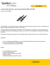
The ARC-1320 SAS host adapters are a line of PCIe 2.0 x8 lanes
6Gb/s SAS bus low prole host adapters. The adapters bring the
fastest available connections to SAS/SATA storage on any com-
puter, workstation and server with PCI Express interface. ARC-1320
host adapters provide a blazing-fast storage connectivity solution
with enhanced reliability and performance and a wide variety of
internal and external connector congurations to support any appli-
cation and tiered storage solution. With connectivity options includ-
ing 8-internal ports, 4-internal/4-external ports, 8-external ports,
and 16-internal/8-external ports, ARC-1320 6Gb/s host adapters
are ideal for large capacity external server storage RAID and no-
RAID enclosure.
ARC-1320 6Gb/s SAS host adapters are able to connect to SATA
and SAS hard disk drives, allowing for tiered storage that optimizes
costs and performance. SAS drives are optimal when speed and
reliability are of the utmost concern while SATA drives are appro-
priate when capacity and cost are more important. System integra-
tors can use the ARC-1320 series to meet different storage infra-
structure applications that support both SAS and SATA devices. API
library for customer combines the ARC-1320 series function code to
its monitor utility.
Device drivers are also supported for the major operating systems
for compatibility with a full range of SAS peripherals including hard
disk drives (HDDs), tape drives, tape autoloaders, solid state drives
(SSDs) and removable media (DAS/JBOD).
1.2 Features
Hardware Specication
• PCIe 2.0 x8 lanes (x8, x4, and x1 lane widths)
• Up to 6Gb/s transfer rates per SAS port

INTRODUCTION
7
• Support 1.5, 3.0 and 6 Gb/s SAS and SATA link rates
• Support a maximum 128 SAS/SATA devices using SAS expander
• Low-prole form factor
• RoHS compliant
Serial Attached SCSI (SAS) 6Gb/s
• Serial Attached SCSI (SAS-2.0) compliant
• Supports Wide port (Any combination of x1, x2, and 4x)
• Supports Serial SCSI Protocol (SSP)
• Supports SAS Management Protocol (SMP)
• Supports Serial ATA Tunneling Protocol (STP)
• Hot-plug capability
• Staggered spin-up control
Easy Management
• Legacy BIOS setup utility
• Supports Command Line Interface (CLI)
• API library for customer to write monitor utility
• Enclosure management for internal port via LED header and
SES2/SGPIO
• Enclosure management for external port via SAS expander
Operating System
• Windows 7, 2008, Vista, 2003 and XP
• Linux (Red Hat and SuSE)
• FreeBSD
• Solaris 10/11 x86/x86-64
• Mac OS X 10.4.x/10.5.x/10.6.x/10.7.x
6Gb/s SAS Host Adapter
Model Name ARC-1320-8i ARC-1320-4i4x ARC-1320-8x ARC-1320ix-16
Host Bus Type PCIe 2.0 x8 Lanes
RAID Level Non-RAID
Form Factor MD2 Low Prole Low Prole
Drives Support 128 X 3Gb/s and 6Gb/s SAS/SATA
Connector 2 x SFF-8087 1 x SFF-8087
1 x SFF-8088
2 x SFF-8088 4 x SFF-8087
2 x SFF-8088
Dimension(LxH) 167 X 64 mm 214 X 64 mm

HARDWARE INSTALLATION
8
2. Hardware Installation
This section describes the procedures for installing the ARC-1320 series
SAS host adapters.
2.1 Before Your Begin Installation
Thanks for purchasing the ARC-1320 series host adapters as your
data storage subsystem. This user manual gives simple step-by-
step instructions for installing and conguring the host adapters.
To ensure personal safety and to protect your equipment and data,
reading the following information package list carefully before you
begin installing.
Package Contents
If your package is missing any of the items listed below, contact
your local dealers before you install.
• 1 x PCIe 2.0 x 8 lanes host adapter in an ESD-protective bag
• 1 x Installation CD – containing driver, relative software, an
electronic version of this manual and other related manual
• 1 x User manual
• 1 x Low-prole bracket
2.2 Board Layout
This section provides the board layout and connector/jumper for
the SAS host adapters.

HARDWARE INSTALLATION
9
Figure 2-1, ARC-1320-8i Host Adapter
Figure 2-2, ARC-1320-8x Host Adapter
Table 2-1, ARC-1320-8i Connectors
Connector Type Description
1. (J2) Manufacture Purpose Port 10-pin header
2. (J1) Global Fault/Activity LED 4-pin header
3. (D4-D11) Activity LED for SAS Port 0-7 SMT LED
4. (D12-D19) Fault LED for SAS Port 0-7 SMT LED
5. (SCN2) SAS 1-4 Ports (Internal) SFF-8087
6. (SCN1) SAS 5-8 Ports (Internal) SFF-8087

HARDWARE INSTALLATION
10
Table 2-2, ARC-1320-8x Connectors
Figure 2-3, ARC-1320-4i4x SAS Host Adapter
Table 2-3, ARC-1320-4i4x Connectors
Connector Type Description
1. (J2) Manufacture Purpose Port 10-pin header
2. (J1) Global Fault/Activity LED 4-pin header
3. (D4-D11) Activity LED for SAS Port 0-7 SMT LED
4. (D12-D19) Fault LED for SAS Port 0-7 SMT LED
5. (SCN3) SAS 1-4 Ports (External) SFF-8088
6. (SCN4) SAS 5-8 Ports (External) SFF-8088
Connector Type Description
1. (J2) Manufacture Purpose Port 10-pin header
2. (J1) Global Fault/Activity LED 4-pin header
3. (D4-D11) Activity LED for SAS Port 0-7 SMT LED
4. (D12-D19) Fault LED for SAS Port 0-7 SMT LED
5. (SCN2) SAS 1-4 Ports (Internal) SFF-8087
6. (SCN3) SAS 5-8 Ports (External) SFF-8088

HARDWARE INSTALLATION
11
Connector Type Description
Front Side
1. (J2) Manufacture Purpose Port 10-pin header
2. (JP1) RS232 for Expander Conguration 10-pin box header
3. (J1) Global Activity/Fault Header 4-pin header
5. (JP2) Individual Fault LED Header for SAS
1-8 Ports
8-pin header
6. (JP3) Individual Fault LED Header for SAS
9-16 Ports
8-pin header
7. (J4) I2C/LCD Connector 8-pin header
8. (SCN2) SAS 5-8 Ports (Internal) SFF-8087
9. (SCN1) SAS 1-4 Ports (Internal) SFF-8087
10. (SCN6) SAS 5-8 Ports (External) SFF-8088
11. (SCN5) SAS 1-4 Ports (External) SFF-8088
Back Side
12. (SCN4) SAS 13-16 Ports (Internal) SFF-8087
13. (SCN3) SAS 9-12 Ports (Internal) SFF-8087
Table 2-4, ARC-1320ix-16 Connectors
Back Side
Figure 2-4, ARC-1320ix-16
SAS Host Adapter
Front Side

HARDWARE INSTALLATION
12
Tools Required
An ESD grounding strap or mat is required. Also required are stan-
dard hand tools to open your system’s case.
System Requirement
The ARC-1320 series host adapters can be installed in a universal
PCIe slot and requires a motherboard that:
• Comply with the PCIe x 2.0 x8 lanes
It can work on the PCIe 1.0/2.0 expansion slot x1, x4, x8, and
x16 signals with x8 or x16 slot M/B.
Installation Tools
The following items may be needed to assist with installing the
ARC-1320 series host adapters into an available PCIe expansion
slot.
• Small screwdriver
• Host system hardware manuals and manuals for the disk or
enclosure being installed.
Personal Safety Instructions
Use the following safety instructions to help you protect your
computer system from potential damage and to ensure your own
personal safety.
• Always wear a grounding strap or work on an ESD-protective
mat.
• Before opening the system cover, turn off power switches and
unplug the power cords. Do not reconnect the power cords until
you have replaced the covers.
Warning:
High voltages may be found inside computer equipment. Be-
fore installing any of the hardware in this package or remov-
ing the protective covers of any computer equipment, turn off
power switches and disconnect power cords. Do not reconnect
the power cords until you have replaced the covers.

HARDWARE INSTALLATION
13
Electrostatic Discharge
Static electricity can cause serious damage to the electronic com-
ponents on this SAS host adapter. To avoid damage caused by
electrostatic discharge, observe the following precautions:
• Do not remove the host adapters from its anti-static packaging
until you are ready to install it into a computer case.
• Handle the host adapters by its edges or by the metal mounting
brackets at its each end.
• Before you handle the host adapters in any way, touch a
grounded, anti-static surface, such as an unpainted portion of the
system chassis, for a few seconds to discharge any built-up static
electricity.
2.3 Installation
Use the following instructions below to install a PCIe host adapter.
Step 1. Unpack the Host Adapters
Unpack and remove the PCIe host adapters from the package.
Inspect it carefully, if anything is missing or damaged, contact your
local dealer.
Step 2. Power PC/Server Off
Turn off computer and remove the AC power cord. Remove the sys-
tem’s cover. For the instructions, please see the computer system
documentation.
Step 3. Install the PCIe SAS Host Adapters
To install the PCIe host adapters, remove the mounting screw and
existing bracket from the rear panel behind the selected PCIe slot.
Align the gold-ngered edge on the card with the selected PCIe
slot. Press down gently but rmly to ensure that the card is prop-
erly seated in the slot, as shown in Figure 2-5. Then, screw the
bracket into the computer chassis. ARC-1320 series host adapters
require a PCIe x8 or x16 slot.

HARDWARE INSTALLATION
14
Step 4. Install Cable
You can connect the end devices to each other through direct
cables or through the SAS expander/backplane connections. The
SAS host adapters support daisy-chain expansion up to 128 end
point devices through SAS expander enclosures. The following is
an example of some internal SAS/SATA cables and an external SAS
cable.
You can connect the SAS/SATA drives to the host adapters through
direct cable and backplane solutions. In the direct connection, SAS/
SATA drives are directly connected to ARC-1320-4i4x or ARC-1320-
8i internal ports with SAS/SATA cables.
Figure 2-5, Insert ARC-1320 series host adapters into a PCIe x8
slot
Note:
Some PCIe slots on desktop board support only graphics
boards, these PCIe slots may be not able to support other
add-on cards such as storage adapters.

HARDWARE INSTALLATION
15
Figure 2-6, SAS cable connect to HD
The following pictures are the cables that can use on ARC-1320
series SAS host adapters with your application.
1: Internal Mini SAS 4i to SATA Cable
The Mini SAS 4i to SATA cables are used for connection between
the ARC-1320ix-16 internal connectors and connectors on the
SAS/SATA disk drives or SATA connector backplane.
The SFF-8448 sideband signals cable is reserved for the backplane
with header on it. Please refer to page 19 for denitions of
sideband header signals.

HARDWARE INSTALLATION
16
Figure 2-7, Internal Min SAS 4i to 4x SATA Cable
Figure 2-8, Mini SAS 4i to 4xSFF-8482 Cable
2: Internal Mini SAS 4i to 4xSFF-8482 Cable
These host adapters can be installed in a server enclosure
without a backplane. The kind of cable will attach directly to the
SAS disk drives. The following diagram shows the picture of Mini
SAS 4i to 4xSFF-8482 cables.

HARDWARE INSTALLATION
17
Figure 2-9, Mini SAS 4i to Min SAS 4i Cable
3: Internal Mini SAS 4i to Internal Mini SAS 4i
Cable
The ARC-1320-4i4x,ARC-1320-8i or ARC-1320ix-16 host adapt-
ers have Mini SAS 4i internal connectors, each of them can sup-
port up to four SAS/SATA signals. These adapters can be installed
in a server RAID enclosure with Mini SAS 4i internal connectors
backplane. This Mini SAS 4i cable has eight signal pins to support
four SAS/SATA drives and six pins for the SGPIO (Serial General
Purpose Input/Output) side-band signals. The SGPIO bus is used
for efcient LED management and for sensing drive locate status.
Figure 2-10, Min SAS 4x to Min SAS 4x Cable
4: External Mini SAS 4x Drive Boxes and Drive
Expander
The Mini SAS 4x external cables are used for connection between
the SAS host adapters external connectors and connectors on the
external drive boxes or drive expanders (JBOD). The SAS host
adapters have Mini SAS 4x (SFF-8088) external connector, each
of them can support up to four SAS/SATA signals.

HARDWARE INSTALLATION
18
The ARC-1320-4i4x, ARC-1320-8x or ARC-1320ix-16 host
adapters can support daisy-chain up to 128 end point devices
through external expander enclosures. The following gure
shows how to connect the external Mini SAS cable from the
ARC-1320-4i4x or ARC-1320ix-16 series host adapters that have
external SFF-8088 connectors to the external drive boxes or drive
enclosures.
Step 5. Install the LED Cable (option)
The preferred I/O connector for server backplanes is the Mini SAS
4i internal connector. This connector has eight signal pins to sup-
portfour SAS/SATA drives and six pins for the SGPIO (Serial Gener-
al Purpose Input/Output) side-band signals. The SGPIO bus is used
for efcient LED management and for sensing drive Locate status.
See SFF 8485 for the specication of the SGPIO bus. For backplane
without SGPIO supporting, Please use the individual cables for
fault/activity LED cable installation.
LED Management: The backplane may contain LEDs to indicate
drive status. Light from the LEDs could be transmitted to the out-
side of the server by using light pipes mounted on the SAS drive
tray. A small microcontroller on the backplane, connected via the
SGPIO bus to a ARC-1320ix-16 could control the LEDs. Activity:
blinking 5 times/second and Fault: solid illuminated.

HARDWARE INSTALLATION
19
Pin Description Pin Description
SideBand0 SClock (Clock signal) SideBand1 SLoad (Last clock of a bit
stream)
SideBand2 Ground SideBand3 Ground
SideBand4 SDataOut (Serial data
output bit stream)
SideBand5 SDataIn (Serial data input bit
stream)
SideBand6 Reserved SideBand7 Reserved
Drive Locate Circuitry: The location of a drive may be detected by
sensing the voltage level of one of the pre-charge pins before and
after a drive is installed.
The following signals dene the SGPIO assignments for the Mini
SAS 4i internal connector (SFF-8087) in the SAS host adapters.
The pin assignment of the sideband inputs follow SFF-8448
specication.
The following signal denes the sideband header signals which can
work with Areca sideband cable on its SFF-8087 to 4 SATA cable.
The sideband header is located at backplane. For SGPIO to
work properly, please connect Areca 8-pin sideband cable to the
sideband header as shown below.
There is no SGPIO supported in the most of old version SATA
backplane. The ARC-1320ix-16/ARC-1320-4i4x/ARC-1320-8i host
adapters also provide two kinds of alternative LED cable header to
support the fault/activity status for those backplanes. The Global
Indicator Connector is used by the server global indicator LED.
The following electronics schematic is the ARC-1320ix-16/ARC-
1320-4i4x/ARC-1320-8i host adapters logical of fault/activity
header. The signal for each pin is cathode (-) side.

HARDWARE INSTALLATION
20
LED Normal Status Problem Indication
Fault LED When the fault LED is solid
illuminated, there is no disk
present. When the fault LED
is off, then disk is present
and status is normal.
When the fault LED is slow blinking
(2 times/sec), that disk drive has
failed and should be hot-swapped
immediately. When the activity
LED is illuminated and fault LED is
fast blinking (10 times/sec) there
is rebuilding activity on that disk
drive.
Note:
A cable for the global indicator comes with your computer
system. Cables for the individual drive LEDs may come with a
drive cage, or you may need to purchase them.
The following diagrams and descriptions describe each type of con
nector.
1: Individual Fault LED Connector
Most of the backplane has supported the HDD activity from the
HDD. The ARC-1320ix-16 SAS host adapter also provides the fault
connector for fault LED. Connect the cables for the drive fault LEDs
between the backplane of the cage and the respective connector on
the SAS host adapters.
The following table is the fault LED signal behavior.
/