Viking BRTGK72SS Operating instructions
- Category
- Fridges
- Type
- Operating instructions
This manual is also suitable for

INSTALLATION
INSTRUCTIONS
BUILT-IN BOTTOM MOUNT REFRIGERATOR/FREEZER
BRTGK72SS/PBRTGK72SS GRILLE KITS
(FOR PROFESSIONAL SERIES ONLY)
VIKING RANGE CORPORATION
111 Front Street
Greenwood, Mississippi 38930 USA
(662) 455-1200
IMPORTANT - PLEASE READ AND FOLLOW
Make sure that incoming voltage is the same as unit rating. An electric rating plate specifying voltage, frequency, wattage,
amperage, and phase is attached to the product.
PPlleeaassee rreeffeerr ttoo IInnssttaallllaattiioonn IInnssttrruuccttiioonnss pprroovviiddeedd wwiitthh bboottttoomm mmoouunntt rreeffrriiggeerraattoorr//ffrreeeezzeerr ffoorr aaddddi
ittiioonnaall iinnffoorrmmaattiioonn..
To reduce the risk of fire, electric shock, or injury to persons, installation work and electrical wiring must be done by qualified
people in accordance with all applicable codes and standards, including fire-rated construction.
The installer should leave these instructions with the consumer who should retain for local inspector’s use and for future
reference.
GENERAL INFORMATION
It is your responsibility to :
-comply with installation specifications and dimensions
-properly install refrigerator
-remove any moldings or decorative panels that prevent the refrigerator from
being serviced
-make sure that you have these materials, (not provided with the unit), which
are necessary for proper installation:
2 - 1/4” (6 mm) copper tubing with shutoff valve
2 - 1/4” (6mm) compression fitting
#8 x 3” (7.6 cm) wood screws (Longer screws may be required.)
BRTGK72SS - Qty 12
PBRTGK72SS - Qty 12
2 - saddle valves (do not use self-piercing valves).
-assure that floor will support refrigerator, door panels and contents,
(approximately 1200 lbs. [540 kg.])
-provide a properly grounded electrical outlet
-assure that location will permit appliance doors to open 90
o
minimum
MMoosstt ooff tthhee rreeffrriiggeerraattoorr’’ss wweeiigghhtt iiss aatt tthhee ttoopp.. EExxttrraa ccaarree iiss nneeeeddeedd wwhheenn mmoovviinngg tthhee
rreeffrriiggeerraattoorr
ttoo pprreevveenntt ttiippppiinngg..
KKeeeepp ccaarrddbbooaarrdd sshhiippppiinngg ppiieeccee oorr ppllyywwoooodd uunnddeerr rreeffrriiggeerraattoorr uunnttiill iitt iiss iinnssttaalllle
edd iinn
tthhee ooppeerraattiinngg ppoossiittiioonn..
YYoouurr ssaaffeettyy aanndd tthhee ssaaffeettyy ooff ootthheerrss
iiss vveerryy iimmppoorrttaanntt..
We have provided many important safety
messages in this manual and on your
appliance. Always read and obey all
safety messages.
This is the safety alert symbol. This
symbol alerts you to hazards that
can kill or hurt you and others.
All safety messages will be
preceded by the safety alert symbol and
the word “DANGER” or “WARNING”.
These words mean:
YYoouu wwiillll bbee kkiilllleedd oorr sseerriioouussllyy iinnjjuurre
edd iiff yyoouu
ddoonn’’tt ffoollllooww iinnssttrruuccttiioonnss..
YYoouu ccaann bbee kkiilllleedd oorr sseerriioouussllyy iinnjjuurreedd iiff
yyoouu ddoonn’’tt ffoollllooww iinnssttr
ruuccttiioonnss..
All safety messages will identify the
hazard, tell you how to reduce the chance
if injury, and tell you what can happen if
the instructions are not followed.
TTIIPP OOVVEERR HHAAZZAARRDD
RReeffrriiggeerraattoorr iiss ttoopp hheeaavvyy aanndd ttiippss eeaassiillyy wwhheenn
nnoott ccoommpplleetteellyy iinnssttaalllleedd..
KKeeeepp ddoooorrss
cclloosseedd uunnttiill rreeffrriiggeerraattoorr iiss
ccoommpplleetteellyy iinnssttaalllleedd aanndd sseeccuurreedd wwiitthh llaagg bboollttss
ttoo rreeaarr wwaallll.. UUssee ttwwoo
oorr mmoorree ppeeooppllee ttoo mmoovvee
aanndd iinnssttaallll rreeffrriiggeerraattoorr.. FFaaiilluurree ttoo ddoo ssoo ccaann
rreessuulltt iinn ddeeaatthh oorr sseerriioouuss iin
njjuurryy

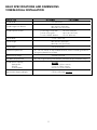
BASIC SPECIFICATIONS AND DIMENSIONS
VCBB363-DUAL INSTALLATION
DDEESSCCRRIIPPTTIIOONN BBRRTTGGKK7722SSSS PPBBRRTTGGKK7722SSSS
Overall Width 72” (182.9 cm)
Overall Height from Bottom Min. 82 3/4” (210.2 cm)
Max. 84 1/16” (213.5 cm)
Overall Depth from Rear To rear edge of side trim 22 3/16” (56.4 cm)
To front of top grille 24 11/16” (62.7 cm)
To end of handle bracket 27 1/4” (69.2 cm)
Cutout Width 71 1/2” (181.6 cm)
Cutout Height Min. 82 7/8” (210.3 cm)
Max. 84 1/16” (213.5 cm)
Cutout Depth 24” (61.0 cm) min.
Electrical Requirements (2) - 115 volt, 60 Hz, 15 amp dedicated circuit; 3-wire cord with grounded 3-
prong plug attached to product.
Maximum Amp Usage 9.9 amps (per unit)
Inlet Water Requirements (2) - 1/4” copper tubing inlet waterline; minimum 20 psi; maximum 120 psi
Overall Interior Capacity
((ppeerr uunniitt))
•Refrigerator 15.2 cu. ft. (.43 cu. meters)
•Freezer 5.1 cu. ft. (.14 cu. meters)
•Total Capacity 20.3 cu. ft. (.57 cu. meters)
Approximate Shipping Weight 575 lbs. (258.8 kg) - per unit
2

3
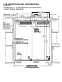
SITE PREPARATIONS AND CONSIDERATIONS
BRTGK72SS
PROFESSIONAL 36” W. BOTTOM MOUNT DUAL INSTALLATION,
CABINET OPENING DIMENSIONS
EELLEECCTTRRIICCAALL
RREECCEEPPTTAACCLLEE
LLOOCCAATTIIOONNSS
((SSHHAADDEEDD AARREEAASS))
11”” ((22..55 ccmm)) TTYYPP
FFOOUURR ((22 ppeerr uunniitt))
8822 77//88”” ((221100..55 ccmm)) MMiinn..
aannttii--ttiipp bbooaarrdd aanndd ooppeenniinngg hheeiigghhtt
8844 11//1166”” ((221133..55 ccmm)) MMaaxx..
aannttii--ttiipp bbooaarrdd aanndd ooppeenniinngg hheeiigghhtt
7711 11//22”” ((118811..66 ccmm)) FFOORR TTWWOO
PPRROOFFEESSSSIIOONNAALL SSTTYYLLEE 3366”” WW..
BBOOTTTTOOMM MMOOUUNNTT RREEFFRRIIGGEERRAATTOORRSS
3355 1133//1166”” ((9911..55 ccmm))
3399 33//1166”” ((9999..55 ccmm))
WWaatteerr lliinnee
eennttrryy aarreeaa
WWaatteerr
lliinnee
WWaatteerr
lliinnee

4
((22 ppeerr uunniitt)) 22”” xx 44”” mmoouunnttiinngg bbooaarrddss ((11--11//22”” [[33..88 ccmm]] xx 33--11//22”” [[88..99 ccmm]]))
NNOOTTEE:: IIff uunniitt iiss iinnssttaalllleed
d ddeeeeppeerr tthhaann 2244”” ((6611..00 ccmm)),, tthheenn sshhiimm bbeehhiinndd aanniitt--ttiipp bbrraacckkeett
tthhiicckknneessss bbyy tthhee ssaammee aammoouunntt..
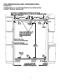
2299”” ((7733..77 ccmm)) 2299”” ((7733..77 ccmm))
33”” ((77..66 ccmm))
33--11//22””
((88..99 ccmm))
33--11//22””
((88..99 ccmm))
BBoottttoomm ooff aannttii--ttiipp bbooaarrdd iiss 33--77//88””
((99..88 ccmm)) bbeellooww ooppeenniinngg hheeiigghhtt..
NNOOTTEE:: TToopp ooff uunniitt mmuusstt bbee
ffiirrmmllyy s
seeaatteedd uunnddeerr aannttii--ttiipp
bbooaarrdd..
66””
((1155..22 ccmm))
66””
((1155..22 ccmm))
99””
((2222..22 ccmm))
Electrical outlet
location
Electrical outlet
location
WWaatteerr lliinnee
eennttrryy aarreeaa
8822--77//88”” ((221100..55 ccmm)) mmiinn..
aannttii--ttiipp bbooaarrdd aanndd ooppeenniinngg hheeiigghhtt
8844--11//1166”” ((221133..55 ccmm)) mmaaxx..
aannttii--ttiipp bbooaarrdd aannd
d ooppeenniinngg hheeiigghhtt
7733--33//88””
((118866..44 ccmm))
SITE PREPARATIONS AND CONSIDERATIONS
PBRTGK72SS
PROFESSIONAL 36” W. BOTTOM MOUNT DUAL INSTALLATION,
CABINET OPENING DIMENSIONS
7711 11//22”” ((118811..66 ccmm)) FFOORR TTWWOO
PPRROOFFEESSSSIIOONNAALL SSTTYYLLEE 3366”” WW..
BBOOTTTTOOMM MMOOUUNNTT RREEFFRRIIGGEERRAATTOORRSS
WWaatteerr
LLiinnee
WWaatteerr
LLiinnee
2244”” ((6611..00 ccmm))

5
BBeeffoorree mmoovviinngg tthhee rreeffrriiggeerraattoorrss iinn ppllaaccee,, ccoonnffiirrmm tthhee ffiinniisshheedd ddiimmeennssiioonnss,, eelleeccttrriiccaall,, aanndd pplluummbbiinngg llooccaattiioonnss,, mmiinniimmuumm
ddoooorr cclleeaarraanncceess,, aanndd ddoooorr ppaanneell iinnssttaallllaattiioonnss aarree aaccccuurraattee.. ((SSeeee IInnssttaallllaattiioonn I
Innssttrruuccttiioonnss pprroovviiddeedd wwiitthh rreeffrriiggeerraattoorrss))..
1. Position refrigerators in front of cutout.
2. Remove the top air grille assemblies from both of the refrigerators.
a. Remove the center grille blades by lifting up and pulling forward.
b. Remove the grille/end cap assembly by removing the four (4) screws in each black air duct.
c. Remove the black air ducts by removing the eight (8) screws on the right hinge model and the seven (7)
screws on the left hinge model. Save the air ducts for the 72” grille installation.
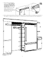
GRILLE ASSEMBLY/INSTALLATION
PROFESSIONAL MODEL
BRTGK72SS
(FOR PBRTGK72SS INSTALLATION - SKIP TO PAGE 9)
SCREW HOLES
(4 Screws on top - 3 Screws on bottom)
(4 Screws on top - 4 Screws on bottom)
TOP VIEW OF GRILLE ASSEMBLY
TOP
EXPLODED SIDE VIEW OF GRILLE ASSEMBLY
(15 Screws Used)
FRONT GRILLE ASSEMBLY
BLACK AIR DUCTS

6
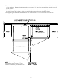
4. Remove cabinet side trim that is mounted on the left hand side of the unit that is to be installed on the right side of
the installation. Replace this side trim with the “Z” shaped side trim and shim included in the full length grille kit.
LLeefftt HHaanndd
CCaabbiinneett SSiiddee TTrriimm
PPoowweerr
SSwwiittcchh
SShhoowwrroooomm
SSwwiittcchh
3. Verify operation by plugging in
power cord. Power switch will
be shipped in the ON position
and showroom switch will be in
the ON position. (If showroom
switch is switched to the “OFF”
position, showroom mode is
engaged and power is shut off to
the compressor. This mode is for
showroom display only.)

7
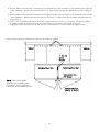
CCaabbiinneett SSiiddee TTrriimm
((NNOOTTEE:: ““JJ”” SShhaappee))
CCaabbiinneett
SSiiddee TTrriimm
((““ZZ”” sshhaappee))
AAnnttii--TTiipp
LLaagg BBoollttss
NNOOTTEE::
When leveling each refrigerator
and installing water connections, refer to
installation instructions provided with each
unit.
5. Remove cabinet side trim that is mounted on the right hand side of the unit that is to be installed on the left side
of the installation. Replace this side trim with the connection “J” shaped side trim and shim included in the full
length grille kit.
6. Place 1” (2.5 cm) spacer material on either left or right hand unit as shown on next page. The spacer material
should be located off the bottom of the unit and should not extend the entire height of the unit.
7. Engage the right hand unit’s left side trim into the J-shaped portion of the left side unit’s right side trim.

8
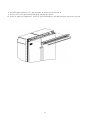
GRILLE ASSEMBLY
REAR VIEW OF
GRILLE ASSEMBLY
BLACK AIR DUCTS
TOP
SCREW HOLES
(16 Holes - 15 Screws)
8. Assemble air ducts to 72” grille using the supplied 15 screws removed in step 2c.
9. Remove 72” center grille blade by lifting up and pulling forward.
10. Insert air ducts and 72” grille into refrigerators. Screw air ducts into units with four screws per unit.

9
GRILLE ASSEMBLY/INSTALLATION
PROFESSIONAL MODEL
PBRTGK72SS
BBeeffoorree mmoovviinngg tthhee rreeffrriiggeerraattoorrss iinn ppllaaccee,, ccoonnffiirrmm tthhee ffiinniisshheedd ddiimmeennssiioonnss,, eelleeccttrriiccaall,, aanndd pplluummbbiinngg llooccaattiioonnss,, mmiinniimmuumm
ddoooorr cclleeaarraanncceess,, aanndd ddoooorr ppaanneell iinnssttaallllaattiioonnss aarree aaccccuurraattee.. ((SSeeee IInnssttaallllaattiioonn I
Innssttrruuccttiioonnss pprroovviiddeedd wwiitthh rreeffrriiggeerraattoorrss))..
1. Position refrigerators in front of cutout.
2. Remove the top air grille assemblies from both of the units
a. Remove full length center grille blade by lifting up and pulling forward.
b. Remove the grille/end cap assembly by removing two (2) screws.
c. Remove grille brackets by removing four (4) screws in each grille assembly.
RREEAARR VVIIEEWW OOFF
GGRRIILLLLEE AASSSSEEMMBBLLYY
TTOOPP VVIIEEWW OOFF GGRRIILLLLEE AASSSSEEMMBBLLYY
72” (182.9 cm)
30 1/32” (76.3 cm)
3 3/8”
(8.6 cm)
4 7/32”
(10.7 cm)
30 7/8“ (78.4 cm)
PPoowweerr
SSwwiittcchh
SShhoowwrroooomm
SSwwiittcchh
3. Verify operation by plugging in
power cord. Power switch
will be shipped in the ON
position and showroom
switch will be in the ON
position. (If showroom switch
is switched to the “OFF”
position, showroom mode is
engaged and power is shut off
to the compressor. This mode
is for showroom display only.)

10
4. Remove cabinet side trim that is mounted on the left hand side of the unit that is to be installed on the right side
of the installation. Replace this side trim with the “Z” shaped side trim and shim included in the full length grille
kit.
5. Remove cabinet side trim that is mounted on the right hand side of the unit that is to be installed on the left side
of the installation. Replace this side trim with the connection “J” shaped side trim and shim included in the full
length grille kit.
6. Place 1” (2.5 cm) spacer material on either left or right hand unit as shown on next page. The spacer material
should be located off the bottom of the unit and should not extend the entire height of the unit.
7. Engage the right hand unit’s left side trim into the J-shaped portion of the left side unit’s right side trim.
CCaabbiinneett SSiiddee TTrriimm
((““ZZ”” SShhaappee))
CCaabbiinneett
CCaabbiinneett
RRiigghhtt HHaanndd DDoooorr UUnniitt
LLeefftt HHaanndd DDoooorr UUnniitt
Double 2x4 mounting board fastened to wall at top of cabinet opening
11”” ((22..55 ccmm))
ssppaacceerr
mmaatteerriiaall
NNOOTTEE::
When leveling each
refrigerator and installing water
connections, refer to installation
instructions provided with each unit.
CCaabbiinneett SSiiddee TTrriimm
((NNOOTTEE:: ““JJ”” SShhaappee))

11
8. Assemble grille brackets to 72” grille using the 16 screws removed in step 2c.
9. Remove 72” center grille blade by lifting up and pulling forward.
10. Insert 72” grille into refrigerators. Screw 72” grille assembly into units with (4) screws removed in step 2b.

Viking Range Corporation
111 Front Street • Greenwood, Mississippi 38930 USA • (662) 455-1200
Specifications subject to change without notice
http://www.vikingrange.com
F20083B (PS0306VR)
-
 1
1
-
 2
2
-
 3
3
-
 4
4
-
 5
5
-
 6
6
-
 7
7
-
 8
8
-
 9
9
-
 10
10
-
 11
11
-
 12
12


Viking BRTGK72SS Operating instructions
- Category
- Fridges
- Type
- Operating instructions
- This manual is also suitable for
Ask a question and I''ll find the answer in the document
Finding information in a document is now easier with AI
Related papers
-
Viking VCFB5363 Installation guide
-
Viking AF/AR User manual
-
-
-
Viking VCRB5363RRE Installation guide
-
-
-
Viking FDFB5303R Installation guide
-
-
Other documents
-
Jenn-Air JCD2290HES User manual
-
-
-
Viking Range VCFB5363 Operating instructions
-
-
Viking Range DFBB536 Installation guide
-
-
-
-
Marvel 1092328 Installation guide