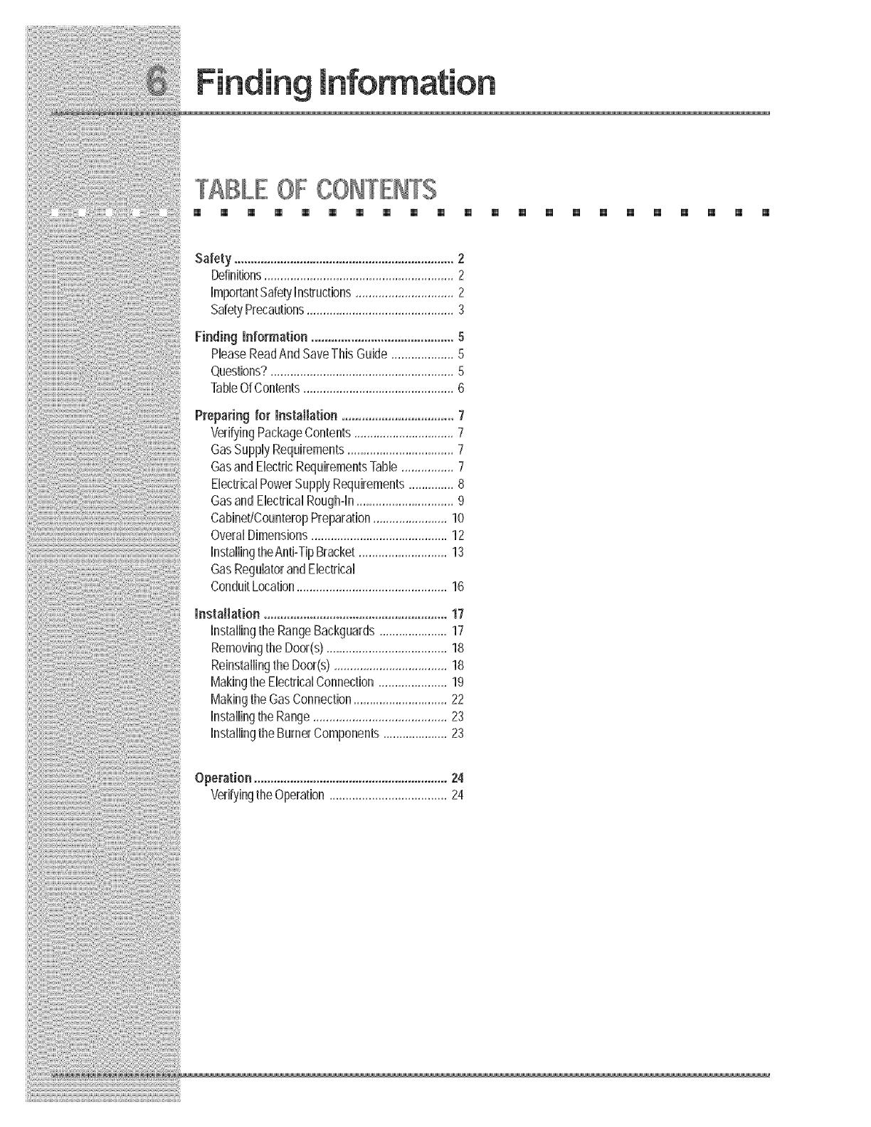
Electrolux E30DF74EPS Installation guide

Category
Cookers
Type
Installation guide

This manual is also suitable for

|nstaMMation |nstructions
MPORTANTSAFEW NSTRUCT ONS
[] [] [] [] [] [] [] [] [] [] [] [] [] [] [] [] [] [] [] [] [] []
Safety Pcecautiens
Do not attempt to install or operate your unit until you have read the safety
precautions in this manual. Safety items throughout this manual are labeled with a
Warning or Caution based on the risk type.
This isthe safetyalertsymbol. Itisused toalertyou to potentialpersonal
injuryhazards. Obey allsafetymessages thatfollowthissymbol toavoid possible
injuryordeath.
SAFETYPRECAUTIONS
[] [] [] lm [] [] [] [] [] [] [] [] [] [] [] [] [] lm [] [] lm []
READANDSAVETHESE NSTRUCT ONS
[] [] [] [] [] m [] [] [] [] m [] m [] [] [] [] m m [] [] []
Read all instructions before installing the Range.
For your safety, please read and observe all safety instructions. This guide will help
you anticipate all installation connections.
[] [] [] [] [] [] [] [] [] [] [] [] [] [] [] [] [] [] [] [] []
For toll4ree telephone support in the U.S. and Canada:
1_877_ 4ELECTROLUX (1_877435_3287)
For online support and Internet product information:
www.e_ectro_uxusa.com
[]
@2005 Electrolux Home Products, Inc,
Post Office Box 212378, Augusta, Georgia 30917, USA
All rights reserve& Printed in the USA
TABLEOF CONTENTS
[] [] [] [] [] [] [] [] [] [] [] [] [] [] [] [] [] [] [] [] [] []
Safety...................................................................2
Definitions..........................................................2
ImportantSafetyInstructions..............................2
SafetyPrecautions.............................................3
Preparingfor mnstaJlation..................................7
%rifyingPackageContents...............................7
GasSupplyRequirements.................................7
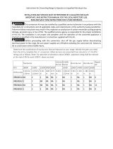
GasandElectricRequirementsTable................7
ElectricalPowerSupplyRequirements..............8
GasandEiedHcaiRough-in..............................9
Cabinet!CounteropPreparation.......................10
OveralDimensions..........................................12
installingtheAnti-TipBracket...........................13
GasRegulatorandElectrical
ConduitLocation..............................................16
mnstallation........................................................17
installingtheRangeBackguards.....................17
RemovingtheDoor(s).....................................18
ReinstallingtheDoor(s)...................................18
MakingtheElectricalConnection.....................19
MakingtheGasConnection.............................22
InstallingtheRange.........................................23
InstallingtheBurnerComponents....................23
Operation...........................................................24
VerifyingtheOperation....................................24
for
VERIFYPACKAGECONTENTS
[] [] [] [] [] [] [] [] [] [] [] [] [] [] [] [] [] []
Use & Care Manual
Broiler Pan/Insert
Anti-tip Bracket
Grate Pack
Griddle
LP Conversion Kit
Burner Rings
Wok Ring
Simmerplate
Stainless Steel Cleaner
o Roasting Rack
, Burner Cap Pack
[] [] [] []
GAS SUPPLYBEQU MENTS
[] [] [] [] [] [] [] [] [] [] [] [] [] [] [] [] [] [] [] [] [] []
Check your local building codes for the proper method of installation. In the
absence of local codes, this appliance should be installed in accordance with the
National Fuel Gas Code ANSI Z223.1. Be certain that the appliance being installed
is correct for the gas service being provided. Refer to the rating label located on the
kick panel and/or the table below for gas supply requirements.
GASANDELECTRICREQUIREMENTSTABLE
[] [] [] [] [] [] [] [] [] [] [] [] [] [] [] [] [] [] [] [] [] []
Refer to the following table for more information on gas and electric requirements.
Model No, Total Gas type Manifold
connected pressure
load
E30DF74EPS
E36DF76EPS
E48DF76EPS
Electrica!
circuit
required
240-4
Wire VAC,
60Hz, 30A
240-4
Wire VAC,
60Hz, 30A
240-4
Wire VAC,
60Hz, 50A
26.4 Amps
(6.3 Kw)
26,4 Amps
(6.3 Kw)
44.2 Amps
(10.4 Kw)
Natural
Liquid Propane
Natural
Liquid Propane
Natural
Liquid Propane
4" Water Column
10" Water Column
4" Water Column
10" Water Column
4" Water Column
10" Water Column
Minimum gas
supply
pressure
5" Water Column
11" Water Column
5" Water Column
11" Water Column
5" Water Column
11" Water Column
for
ELECTRICAL POWER SUPPLY REQUREMENTS
[] [] [] [] [] [] [] [] [] [] [] [] [] [] [] [] [] [] [] [] [] []
It is the owner's responsibility to ensure that the electrical connection of this
appliance is performed by a qualified electrician. The electrical installation,
including minimum supply wire size and grounding, must be in accordance with the
National Electric code ANSIiNFPA 70- 1993* (or latest revision) and local codes and
ordinances.
*A copy of this standard may be obtained from:
National Fire Protection Association
1 Batterymarch Park
Quincy, Massachusetts 02269-9101
The correct voltage, frequency, and amperage must be supplied to the appliance
from a separate, grounded, circuit that is protected by a properly sized circuit
breaker or time delay fuse.
Refer to the Gas and Electrical Requirements Table on page 7.
for
@ASANDELECTRiCaLR@U@Ho H
[] [] m m [] [] [] [] [] [] [] [] [] [] [] [] [] [] [] [] [] []
A manual shut valve must be installed in the gas piping, external to the appliance,
for the purpose of turning on or shutting off gas to the appliance. Plan the location
of the range and the gas supply to allow access to the valve when the unit is
installed. Access to the remote circuit breaker panel/fuse box, with the range in
place, must also be allowed for in the installation. Any openings in the wall behind
the appliance and in the floor under the appliance must be sealed.
Both the gas supply piping and shut-off valve, and the electrical junction box/
receptacle must be located so they do not interfere with the range when it is
installed. In addition, the junction box must be located so the range can be removed
for service when the conduit supplied with the unit is attached to the junction box.
Do not lengthen the conduit or wiring provided with the range.
All dimensions shown are based on standard American cabinets 36 inches
(914mm) high at the finished countertop by 24 inches (610mm) deep, with a 25
inch (635mm) overall countertop depth. When installing the range into nonstandard
cabinets, minimum clearances shown in the diagrams on page 11 must be
maintained.
Carefully check the location where the range is to be installed. For best
performance, the range should be placed away from drafts that may be caused by
doors, windows and HVAC outlets.
for'
CABINETAND COUNTE ©P PREPARATION
[] [] [] [] [] [] [] [] [] [] [] [] [] [] [] [] [] [] [] [] [] []
for
Plan the installation so that the electrical connection, gas shut=off valve, and
pressure regulator are accessible from the front of the cabinet.
Figure 1
(330ram)
Minumim
10" (254mm) Min.
to combustLble side
wails above the range
(both sides)
25"
(635mm)
E30DF74EPS, E36DF76EPS and
E48DF76EPS
Cutout Dimensions
ModeJ "A.... B"
E3ODF74EPS 36"(914mm}Recommended 301/16"(764mm}
30"(762mm}Minimum
E36DF76EPS 42"(1067mm)Recommended 361/16"(914mm)
3d' (914mm)Minimum
E48DF76EPS 54"(1372mm}Recommended 481/8" (1222mm}
48"(1219mm}Minimum
for
OVERALLD MENS ONS
[] [] [] [] [] [] [] [] [] [] [] [] [] [] [] [] [] [] [] [] [] []
E36DF76EPS and E48DF76EPS Overall Dimensions
Side View
--30 3/8" (772 ram}
-- 29 I/8" (740 ram}
--28 //8" (714 ram)-
-26 1/2" [673 mm)
Handle
font Edge of Bulllnose
Face of Con[rol panel/Oven Door
Rear of Corffrol panel/Oven Door
24" (68 n!m)
Back _ua!d
3"
(79 mm)
9" (229 ram)
Back uad
Backguord
37" (9 , rf'm)
to
35 3/4' i
Figure 2
E30DF74EPS Overall Dimensions
Side View
_, 28 ]/4'
[718 1mini
27 3/8" _.
[693.7mm]
24 1/8"
[6125mini
25 5/8"
[652 lmm]
Figure 3
HANDLE
FRONT EDGE OF BULLNOSE
FACE OF CONTROL PANEL
REAR OF CONTROL PANEL
6" [I 52MM 1 BACKSPLASH
T
7"
[940mm]
to
35=3/4"
[90ti_r"_]
for
IISTRLLIIQ THEAITI-TII BRACKET(FOR _", S8'=&
18'=IODELS}
[] [] [] [] [] [] [] [] [] [] [] [] [] [] [] [] [] [] [] [] [] []
Installation of E30DF74EPS Anti-Tip Bracket
Figure4
J
All Dimensions are from
Cabinet Only
(Not Counferfop)
30 1/16"
(122]mm}
BASE
Location of the E30DF74EPS Anti-Tip Bracket
FigureS
REAR
Anti-tip bracket
location on left
rear leg
\
\
\
\
\
Pc÷ ° for
IISTRLLII@ THERITI-TIP B_OKET iFOR _'=, 38'=&
41,=IOIELS}
[] m [] [] [] [] [] [] [] [] m [] [] [] m [] [] [] [] [] []
Back wall
Installation of E36DF76EPS Anti-Tip Bracket
Top View
7 1/2"
(191mm)
24" (610mm 1
I
j 18 1/32"
i (458mm)
36 1/16"
Figure 6
Dimensions are
from Cabinet Only
(Not Countertop)
(916mm)
Rear
Leveler
5/16- 18x2
or Equivalent
"_ Left
.......... Rear
Leg
Location of the E36DF76EPS Anti-Tip Leveler
Figure 7
for
IISTRLLIIQ THEAITI-TIP BRACKET(FOR _", 18'=&
18'=IOIEL$}
[] [] m m [] m [] [] [] [] m m [] [] m [] [] m m [] E
Installation of E48DF76EPS Anti-Tip Bracket
4 9/16" j
(115mm} I
J
t '
1
1
1
1
1
1
1
1
1
All Dimensions "
are from L
Cabinet Only
(Not Counfedop)
TopView
135/16"
(339mm)
L!,
48 1/16"
(1221mm)
Figure 8
BACK WALL
Figure 9
Rear
Leg
Location of the E48DF76EPS Anti-Tip Leveler
" Leveler
5/16 - 18 × 2
or Equivalent
for
@ASR U_T©R ANDELECTRICALC@N _T
[] [] [] [] [] [] [] [] [] [] [] [] [] [] [] [] [] [] [] [] [] []
Figure 10 ....................................................................................................................................................
Factory installed j
3/4"regulator
(1/2" supply ok)
Power cord /
Gas Regulator and Electrical Conduit Location
Rear View
NSTALUN@ THE 38 & 48 NGE ©PT @NAL
BACKGUARDS
[] [] [] [] [] [] [] [] [] [] [] [] [] [] [] [] [] [] [] [] [] []
Your EtectroluxIconTM range was shipped witha backguard inplace.These
instructions cover the installation of one of the optional backguards.
mnstaHing the Range Optiona_ Backguard:
1. Remove the backguard from its box.
2. To avoid scratches, place small scraps of thin cardboard on the rear of
the side panels where the backguard will make contact. With the
assistance of at least one other person, carefully lift the backguard and
place down on to the range top. Special attention should be given to the .....
lower flange in front of the backguard, which must fit between the
stainless steel side panels.
3. Fasten the provided screws through the rear flange.
4. Connect the gas line to the regulator. Reposition and attach the access
panel or the back cover if the entire back cover was removed.
5. You are now ready to continue with the range installation.
Figure 11
BackguarU
Backguard Installation
(36" range shown)
Figure 12
Backguard Installation
(48" range shown)
{ {: { {:
{{:{{??{
:: {{ { Open the door to its fully opened position. Rotate the catch over the retaining arm
on each hinge. Lift the oven door to about a 30 degree angle from the horizontal
_osition. Pull the door away from the oven while continuing to lift.
Figure 13
:::::: ::::: ::: ....
: :: :: :: :: :: :: :: :: :: :: :: :: :: :: :: :: ::
..........................................................................................................................................To remove
oven door,
rotate catch /_
as shown.
Removing the Oven Door
REo_STALL_HGTHEOVEHBOOR{S}
[] [] [] [] [] [] [] [] [] [] [] [] [] [] [] [] [] [] [] [] [] []
Grasp the oven door on opposite sides and lift it until the door hinges are aligned
with the openings in the oven frame. Holding the door at about a 30 ° angle from the
horizontal, slide the hinges into the openings until the bottom hinge arms drop fully
into the hinge receptacles. Lower the door to the fully opened position, and then
rotate the two hinge catches toward the oven.
Open and close the door completely to ensure that it is properly installed.
Peel off the protective layer of plastic that covers the door panel.
MAK H@THEELECTRICALCONNECTION
[] [] m [] m m [] [] m [] m [] m [] [] [] [] [] [] m [] []
Grounding mnstcuctions
This appliance must be electrically grounded. With the range positioned
directly in front of the cabinet cutout, feed the appliance conduit to the electrical
junction box. Then, depending upon Focal codes, utilize one of the following
techniques to connect the appliance to the electrical power supply:
Connecting to a Four-Wire Electrica_ System
1. Separate the green and white appliance wires.
2. Connect the white appliance wire to the
neutral (white) supply wire in the junction
box.
3. Connect the black appliance wire to the
black (L1) power supply wire in the
junction box.
4. Connect the red appliance wire to the red
(L2) power supply wire in the junction box,
5. Connect the green appliance wire to the
green house grounding wire in the junction
box.
Figure 14 Cable from
power supply
Conduit from
appliance
Connecting the appliance to a
four-wire power supply
Connectingthe GreenApplianceWireto the Neutral(White)Supply
Wire=WhereLocalCodesPermit
1 Connect the green and white appliance wires to the neutral (white) supply
wire in the junction box.
2 Connect the black appliance wire to the black (L1) power supply wire in the
junction box,
3 Connect the red appliance wire to the red (L2) power supply wire in the
junction box.
Figure 15 Cable from
power supply
RED GREEN
RED
Wire nut
(3 places)
Conduit from
appliance
Connecting the appliance to a
three-wire power supply
  • Page 1 1
  • Page 2 2
  • Page 3 3
  • Page 4 4
  • Page 5 5
  • Page 6 6
  • Page 7 7
  • Page 8 8
  • Page 9 9
  • Page 10 10
  • Page 11 11
  • Page 12 12
  • Page 13 13
  • Page 14 14
  • Page 15 15
  • Page 16 16
  • Page 17 17
  • Page 18 18
  • Page 19 19
  • Page 20 20
  • Page 21 21
  • Page 22 22
  • Page 23 23
  • Page 24 24
  • Page 25 25
  • Page 26 26
  • Page 27 27
  • Page 28 28
  • Page 29 29
  • Page 30 30
  • Page 31 31
  • Page 32 32
  • Page 33 33
  • Page 34 34
  • Page 35 35
  • Page 36 36

Electrolux E30DF74EPS Installation guide

Category
Cookers
Type
Installation guide
This manual is also suitable for

Ask a question and I''ll find the answer in the document

Finding information in a document is now easier with AI