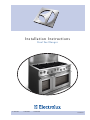
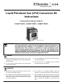
Electrolux E36DF76EPS Installation Instructions Manual
- Category
- Ovens
- Type
- Installation Instructions Manual
This manual is also suitable for
Electrolux E36DF76EPS is a dual fuel range that combines the precision of gas cooktops with the even heating of electric ovens. It offers a variety of features to make cooking easier and more enjoyable, including:
- Five gas burners: The gas cooktop features five burners, including a powerful 15,000 BTU burner for rapid boiling and a 5,000 BTU simmer burner for delicate sauces.
- Two electric ovens: The electric ovens offer a total of 6.6 cubic feet of cooking space, providing ample room for large meals and multiple dishes. The ovens feature convection cooking for faster and more even cooking, as well as a self-cleaning cycle for easy cleanup.


-
 1
1
-
 2
2
-
 3
3
-
 4
4
-
 5
5
-
 6
6
-
 7
7
-
 8
8
-
 9
9
-
 10
10
-
 11
11
-
 12
12
-
 13
13
-
 14
14
-
 15
15
-
 16
16
-
 17
17
-
 18
18
-
 19
19
-
 20
20
-
 21
21
-
 22
22
-
 23
23
-
 24
24
-
 25
25
-
 26
26
-
 27
27
-
 28
28
-
 29
29
-
 30
30
-
 31
31
-
 32
32
-
 33
33
-
 34
34
-
 35
35
-
 36
36


Electrolux E36DF76EPS Installation Instructions Manual
- Category
- Ovens
- Type
- Installation Instructions Manual
- This manual is also suitable for
Electrolux E36DF76EPS is a dual fuel range that combines the precision of gas cooktops with the even heating of electric ovens. It offers a variety of features to make cooking easier and more enjoyable, including:
- Five gas burners: The gas cooktop features five burners, including a powerful 15,000 BTU burner for rapid boiling and a 5,000 BTU simmer burner for delicate sauces.
- Two electric ovens: The electric ovens offer a total of 6.6 cubic feet of cooking space, providing ample room for large meals and multiple dishes. The ovens feature convection cooking for faster and more even cooking, as well as a self-cleaning cycle for easy cleanup.
Ask a question and I''ll find the answer in the document
Finding information in a document is now easier with AI
Related papers
-
Electrolux E36DF76EPS Installation guide
-
Electrolux E36GF75GPS User manual
-
Electrolux EW30ES65GSF Installation guide
-
Electrolux E48WV12EPS User manual
-
Electrolux 5995447108 User manual
-
-
-
-
Electrolux E36GC75GSS User manual
-
Other documents
-
Koala Kare 1064-KIT-C Operating instructions
-
Cosmo 850SLTX-E User guide
-
Dacor ER30DSR User manual
-
-
Thermador PRG304 User manual
-
Thermador Range PRDS48 User manual
-
-
Jenn-Air JDR8880RDB1 Installation guide
-
-
Dacor ERD30S06NG Installation guide