Gembird EG-PMS2 User manual
- Category
- Surge protectors
- Type
- User manual
This manual is also suitable for

USER MANUAL
HANDBUCH
HANDLEIDING
MANUEL DESCRIPTIF
РУКОВОДСТВО ПОЛЬЗОВАТЕЛЯ
КЕРІВНИЦТВО КОРИСТУВАЧА
EG-PMS2 PROGRAMMABLE USB SURGE
PROTECTOR

2
EG-PMS2
PROGRAMMABLE USB SURGE PROTECTOR
All brands and logos are registered trademarks of their respective owners
PROGRAMMABLE SURGE PROTECTOR
PROGRAMMIERBARE STECKDOSENLEISTE
PROGRAMMEERBARE STEKKERDOOS
PARASURTENSEUR PROGRAMMABLE
ПРОГРАММИРУЕМЫЙ СЕТЕВОЙ ФИЛЬТР
ПРОГРАМОВАНИЙ СЕТЕВОЙ ФІЛЬТР
Do not plug several sockets in line
Do not use if covered
De-energized only if power plug is unplugged
NEVER connect appliances which does not allow unattained
operation !

3
EG-PMS2
PROGRAMMABLE USB SURGE PROTECTOR
All brands and logos are registered trademarks of their respective owners
1. Introduction
Congratulations with your purchase of this Energenie Power
Manager. Your EG-PMS2 is an advanced surge protector with power
management features. Four sockets are individually manageable by the
computer via USB interface.
The sockets can be switched on/off by a timer schedule, by user or
different events. It is also possible to pre-program the unit event timer
schedule (hardware schedule) and then disconnect EG-PMS2 from the
managing computer. The device can be used as an advanced standby-
killer.
1.1. Features
The main rocker switch enables switching all the sockets on and off
In addition to it every manageable socket can be switched on and off
via the software control window
The unit can be pre-programmed via hardware-based schedule. The
hardware schedule will work even when the managing computer is
switched off
The unit will keep performing the programmed hardware time
schedule even after EG-PMS2 is disconnected from the power for
some time

4
EG-PMS2
PROGRAMMABLE USB SURGE PROTECTOR
All brands and logos are registered trademarks of their respective owners
The manageable sockets can then be switched on and off by the
schedule, simple typical applications could be: “switch my
peripherals on every working day at 8:50 AM” etc.
The manageable sockets can also be programmed with Power
Manager software to react whenever a certain event occurs
(Windows or other programs start-up/shutdown), simple typical
applications could be: “switch my scanner on when I want to scan”
or “switch my printer off whenever I exit Windows”
1.2. Specifications
Input voltage: max 250 VAC, 50 – 60 Hz
Maximum load current: 10 A
Maximum power consumed by EG-PM2: 2.5 W
Built-in power supply
Surge: Type3, Up = 1.2 kV for L-N, Uoc = 4 kV for L-N Uo = 230 V
Uc = 250V Ucs = 1.1 x 230 V = 253 V
Hardware schedule features:
Maximum number of independent hardware schedule events – 16
per socket
Time interval between the events – from 1 minute to 180 days
Timer accuracy: no more than 2 seconds error per day providing
power is always present. Otherwise there can be an additional (up to
2 seconds) error per each power off.

5
EG-PMS2
PROGRAMMABLE USB SURGE PROTECTOR
All brands and logos are registered trademarks of their respective owners
Indoor use.
Dimensions: 378 x 98 x 55 mm
Net weight: 1 kg
1.3. Hardware requirements
Computer running Windows® 2000/XP/Vista/7 or Windows 8 is
required for using the Power Manager software
One free USB port
1.4. Package contents
The package contains:
EG-PMS2
User manual
USB cable
CD with Power Manager software for Windows

6
EG-PMS2
PROGRAMMABLE USB SURGE PROTECTOR
All brands and logos are registered trademarks of their respective owners
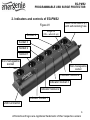
2. Indicators and controls of EG-PMS2
Figure #1
Main rocker switch (Z)
with self-restoring fuse
Indicator Socket 3
Non-manageable
socket
Indicator Socket 4
Indicator Socket 2
Indicator Socket 1
Non-manageable
socket
Socket 4
Socket 3
Socket 2
Socket 1
USB Connector
Surge Ok
(Ok – when lit up)

7
EG-PMS2
PROGRAMMABLE USB SURGE PROTECTOR
All brands and logos are registered trademarks of their respective owners
2.1. Indicators
Main rocker switch Z with built in self recovering fuse (see Figure #1
above) is lit – this means that EG-PMS2 is connected to the power
supply and active
The indicator Socket 1 (2,3,4) (see Figure #1 above) is lit – this
means that this particular socket is switched on
The indicator Surge Ok (see Figure #1 above) stays on if the surge
protection is well functioning and non-manageable sockets (first and
last) are switched on
3. Installation
It is strongly recommended to avoid damp or wet places for
installation.
EG-PMS2 should be connected to the European AC wall socket of
the standard DIN 49 440.
Do not plug several sockets in line
Do not use if covered
De-energized only if power plug is unplugged
NEVER connect appliances which does not allow unattained
operation !

8
EG-PMS2
PROGRAMMABLE USB SURGE PROTECTOR
All brands and logos are registered trademarks of their respective owners
3.1. Getting started
Connect EG-PMS2 to the wall socket first and then to the USB
socket of the manageable computer.
EG-PMS2 can now be switched on and off by means of the Main
rocker switch (Z).
Two (the first and the last) sockets of EG-PMS2 are switched on and
off by means of the Main rocker switch (Z) and cannot be managed
by the computer – so they are called non-manageable sockets in
this manual.
If EG-PMS2 is switched on then the Surge OK indicator is lit. In this
case both non-manageable sockets are now live and connected to
the power supply.
The sockets: Socket 1, Socket 2, Socket 3 and Socket 4 can be
managed or pre-programmed by computer via USB. They are called
manageable sockets in this manual.
The manageable sockets of EG-PMS2 can be programmed to be on
or off. The current status of each manageable socket is represented
by the corresponding indicator which will be lit if the socket has
power to it.
If the Main rocker switch (Z) (see figure #1 above) is turned off then
the manageable sockets cannot be switched on by either Power
manager software or the hardware schedule.

9
EG-PMS2
PROGRAMMABLE USB SURGE PROTECTOR
All brands and logos are registered trademarks of their respective owners
As soon as you turn the Main rocker switch (Z) on then the Power
manager software or the hardware schedule will be able to turn the
manageable sockets on and off.
To protect the connected devices from possible high current and
short circuit EG-PMS2 is equipped with the automatic circuit breaker.
NOTE: If the total power consumption (or peak power) of the devices,
connected to EG-PMS2 exceeds 2200 Watts, the circuit breaker may
power EG-PMS2 off. In this case, please, remove the excessive load
first and then (after 2-3 minutes) press the main rocker switch (Z) to
restore the power supply.
3.2. Power Manager installation
Insert the Power Manager CD into a PC CD-ROM drive.
If for any reason the automatic setup does not work, then open CD-ROM
drive in the My Computer window and launch SETUP.EXE from the CD
Follow instructions of the installation software
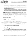
4. Power Manager software
The Power Manager software is designed to support not only EG-
PMS2 but also other energy management products of the EnerGenie

10
EG-PMS2
PROGRAMMABLE USB SURGE PROTECTOR
All brands and logos are registered trademarks of their respective owners
family. After a successful installation a socket icon will appear in
your system tray.
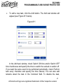
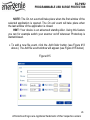
4.1. Managing EG-PMS2
Double click on the socket icon in the system tray or select Open
from the popup menu, you will get the windows with device list (see
Figure #2 below).
Figure #2

11
EG-PMS2
PROGRAMMABLE USB SURGE PROTECTOR
All brands and logos are registered trademarks of their respective owners
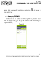
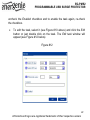
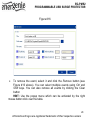
Push the Device settings button (bottom right here) to set the device-
specific options (see Figure #3 below)
Figure #3
Double click on the device and you will get the window of the main
control panel shown on the Figure #4 below.

12
EG-PMS2
PROGRAMMABLE USB SURGE PROTECTOR
All brands and logos are registered trademarks of their respective owners
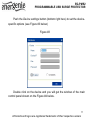
Figure #4
Double click on each socket will switch it on or off (green color
means the socket is switched on; red color means the socket is switched

13
EG-PMS2
PROGRAMMABLE USB SURGE PROTECTOR
All brands and logos are registered trademarks of their respective owners
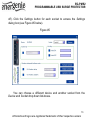
off). Click the Settings button for each socket to access the Settings
dialog box (see Figure #5 below).
Figure #5
You can choose a different device and another socket from the
Device and Socket drop down list-boxes.

14
EG-PMS2
PROGRAMMABLE USB SURGE PROTECTOR
All brands and logos are registered trademarks of their respective owners
It is possible to give a name to the device and socket (for example
Printer or Scanner) using the Rename button
Check the System tray checkbox if you want to put the icon of the
socket into the system tray. You can choose the icon from drop
down list box. Such icon is a fast way to switch the device connected
to the socket on/off or check the device status
You can also assign a hot key to switch the socket on/off. Check the
Switch ON and Switch OFF checkboxes and specify the hot keys
To switch the socket on/off on Windows startup (wake up), check the
On Windows startup checkbox and choose the required action
To switch the socket on/off on the Windows shutdown (sleep), check
the On Windows shutdown checkbox and choose the required action.

15
EG-PMS2
PROGRAMMABLE USB SURGE PROTECTOR
All brands and logos are registered trademarks of their respective owners
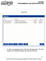
4.2. Setting up the hardware schedule
Using the Hardware schedule button available from the Settings
window you can create the hardware timer schedule (see Figure #6
below). To add a new record, click the Add button.
Figure #6

16
EG-PMS2
PROGRAMMABLE USB SURGE PROTECTOR
All brands and logos are registered trademarks of their respective owners
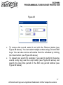
The window Add entry will appear (see Figure #7 below). In the
dialog box, specify the required time and the action
Figure #7
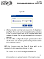
To edit the record, select it and click the Edit button or just double
click on the entry. The window Edit entry will appear (see Figure #8
below)

17
EG-PMS2
PROGRAMMABLE USB SURGE PROTECTOR
All brands and logos are registered trademarks of their respective owners
Figure #8
To remove the record, select it and click the Remove button (see
Figure #6 above). You can select multiple entries using Ctrl and Shift
keys. You can also remove all entries from the schedule by clicking
the Clear button (see Figure #6 above)
To repeat your event (for example if you want to perform the same
events every day) use the Loop button (see Figure #6 above) and
specify the loop time period in the Edit loop period window (see
Figure #9 below)

18
EG-PMS2
PROGRAMMABLE USB SURGE PROTECTOR
All brands and logos are registered trademarks of their respective owners
Figure #9
After the schedule record has been created, click the Apply button
(see Figure #6 above) to save the hardware timer schedule changes.
In case of incorrect entries, these will be highlighted and an error
message will appear. Click the Apply button again after correcting all
the errors
Use Sync button (see Figure #6 above) to synchronize device timer
with PC clock. Note that after synchronization past entries will be
removed from the schedule
HINT: Use the popup menu (see Figure #6 above) which can be
activated by the right mouse button click over the table.
The following are the rules for creating a correct schedule:

19
EG-PMS2
PROGRAMMABLE USB SURGE PROTECTOR
All brands and logos are registered trademarks of their respective owners
The new event time should be in the future
There can not be a duplicate entry
The total quantity of events can not exceed 16 per socket
The total quantity of events also depends on the total execution
period of the schedule
The interval between the present and the last entry can not exceed
180 days
Without loop the total execution period of the schedule can not
exceed 215 days
Loop period can not exceed 180 days
NOTE: If the device is powered off the hardware schedule is still in
the device memory and will be resumed when the power supply is
restored. However the whole schedule will be then delayed with the
power cutoff time. You can adjust the schedule eliminating the delay.
Alternatively create and upload a new schedule using the ‘Timer
schedule’ dialog box.

20
EG-PMS2
PROGRAMMABLE USB SURGE PROTECTOR
All brands and logos are registered trademarks of their respective owners
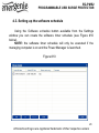
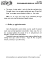
4.3. Setting up the software schedule
Using the Software schedule button available from the Settings
window you can create the software timer schedule (see Figure #10
below).
NOTE: the software timer schedule will only be executed if the
managing computer is on and the Power Manager is launched.
Figure #10
Page is loading ...
Page is loading ...
Page is loading ...
Page is loading ...
Page is loading ...
Page is loading ...
Page is loading ...
Page is loading ...
Page is loading ...
Page is loading ...
Page is loading ...
Page is loading ...
Page is loading ...
Page is loading ...
Page is loading ...
-
 1
1
-
 2
2
-
 3
3
-
 4
4
-
 5
5
-
 6
6
-
 7
7
-
 8
8
-
 9
9
-
 10
10
-
 11
11
-
 12
12
-
 13
13
-
 14
14
-
 15
15
-
 16
16
-
 17
17
-
 18
18
-
 19
19
-
 20
20
-
 21
21
-
 22
22
-
 23
23
-
 24
24
-
 25
25
-
 26
26
-
 27
27
-
 28
28
-
 29
29
-
 30
30
-
 31
31
-
 32
32
-
 33
33
-
 34
34
-
 35
35


Gembird EG-PMS2 User manual
- Category
- Surge protectors
- Type
- User manual
- This manual is also suitable for
Ask a question and I''ll find the answer in the document
Finding information in a document is now easier with AI
Related papers
-
Energenie EGM-PWM User manual
-
Gembird EG-PM2 User manual
-
Energenie EG-PM2 User manual
-
Energenie EG-SMS User manual
-
Energenie EGM-PWML User manual
-
-
Energenie EG-SP5-U6B-RM User manual
-
Energenie SPG-RM User manual
-
Gembird MUSG-02 User manual
-
Energenie EG-UPS-033 User manual
Other documents
-
Energenie EG-PMS2-LAN Datasheet
-
-
Roche BenchMark XT/LT Interpretation Guide
-
-
Energenie EG-PMS2-WLAN Datasheet
-
-
Hitachi 61HDX98B User manual
-
Pyle PMS2 User manual
-
Energenie EG-PM1W-001 User manual
-
Hitachi 57GWX20B Training