Extron electronics MLA-VC10 User manual

Category
Power supply units
Type
User manual

This manual is also suitable for

1
MLA VC10 Plus • Setup Guide
The Extron MLA VC10 Plus Volume Control Module converts RS-232 commands from a
control system into voltage or impedance changes to control audio amplifiers with volume
and mute control ports. The MLA VC10 Plus mutes or makes level changes on an Extron
MPA Series or half rack XTRA
Series amplifier from a TouchLink
Touchpanel system, an
RS-232-capable MediaLink
®
Control Processor, or a third-party control system. The control
module also supports third-party amplifiers that use either variable voltage or 10 kilohm
potentiometer control.
This setup guide provides instructions for quick installation and configuration of the
MLA VC10 Plus with Extron products or some common third-party amplifiers. Installation
and service must be performed by experienced installers only. For complete features,
functions, and configuration instructions, read the user guides that come with your control
processor and amplifier and see the MLA VC10 Plus User Guide, which is available at
www.extron.com.
CONFIG
RELAY
MUTE
MLA VC10 Plus
R
a
b
c
e
d
RS-232
RELAY
V-DC
R
Tx Rx GG GVC
NO NCC
POWER
0.3A MAX
12V
CONTROL
OUTPUT
REMOTE
fg jih
Front Panel
a
Power and Activity LED
b
Mute LED
c
Relay LED
d
USB Configuration Port
e
Reset Button
Rear Panel
f
Power input
g
RS-232 Control
h
Variable Voltage Control
i
Resistance (Potentiometer)
Control
j
Relay Control
MLA VC10 Plus • Setup Guide (Continued)
2
Application Diagram
RS-232
RELAY
V-DC
R
Tx Rx G G GV C
NO NCC
POWER
0.3A MAX
12V
CONTROL
OUTPUT
REMOTE
CONFIG
DISPLAY
VOLUME
1
2
3
4
ON
OFF
MLC 104 IP PLUS
VCR
DVD
PC
XPA 1002
1 2
LIMITER/PROTECT
SIGNAL
OVER
TEMP
Extron
MLC 104 IP Plus
MediaLink
Controller
Extron
MLA VC10 Plus
Volume Control Module
RS-232
Variable
Impedance
Output
Extron
XPA 1002
Power
Amplier
Extron
SI 26
Surface-mount
Speakers
Installation
Decide where the unit will be installed. Read the “Mounting” section of the MLA VC10 Plus
User Guide for mounting options.
NOTES: The majority of amplifiers researched and tested by Extron work with
the MLA VC10 Plus default settings as the unit is shipped, with no further
configuration needed.
To avoid picking up background noise in the cable, use shielded cable, such
as Extron STP 22 cable (see www.extron.com) and place the MLA VC10 Plus
as close as possible to the amplifier. The recommended cable length between
the MLA VC10 Plus and the amplifier should be six feet or less.
3
Remote Volume Control Connections to Ampliers
The following examples show how to wire the resistance control terminals of the
MLA VC10 Plus to an Extron MPA or XPA Series amplifier, or some common third-party
amplifiers.
Other amplifiers not shown here require similar connections but you must read the
appropriate user guides to ensure the wiring is correct.
Extron MPA or XPA Series Amplier
1. Connect the reference voltage
wire (V) of the MLA VC10 Plus
to the reference terminal of the
amplifier (10V on the MPA; V on
the XPA).
2. Connect the ground wire (G) of
the MLA VC10 Plus to the ground
terminal on the amplifier (
on
the MPA; G on the XPA).
3. Connect the control signal wire
(C) of the MLA VC10 Plus to the
control signal terminal of the
amplifier (Vol/Mute on the MPA;
C on the XPA).
Third-party Amplier (Three-pin Connection)
This example shows the MLA VC10 Plus
connected to an Ashly NE Series amplifier.
1. Connect the reference voltage wire (V) from
the MLA VC10 Plus to the reference voltage
terminal (+5V) on the amplifier.
2. Connect the ground wire (G) from the
MLA VC10 Plus to the ground terminal (Gnd)
on the amplifier.
3. Connect the control signal wire (C) from the
MLA VC10 Plus to the control signal terminal
(Ch 1) on the amplifier.
Third-party Amplier (Two-pin Connection)
This example shows the MLA VC10 Plus connected to
a TOA 900 Series amplifier.
1. Connect the ground wire (G) from the
MLA VC10 Plus to the left Remt Vol terminal on
the amplifier.
2. Connect both the reference wire (V) and the
control signal wire (C) from the MLA VC10 Plus
to the right Remt Vol terminal on the amplifier.
Ground
Reference
Extron MLA VC10 Plus
Ashly NE serie
s
CH 4
CH 3
CH 2
GND
+5V
CH 1
Control (variable)
G
C
V
R
GVC
Ground
Reference
Control (variable)
G
C
V
G
C
V
Extron
MLA VC10 Plus
REMOTE
VOL/MUTE
10V 50mA
Extron MPA
Amplifier
R
GVC
Extron
Half-rack
XPA Series
Amplifier
10V 50mA
GVC
G
STANDBY
OR
G Ground
REMT
VOL
MUTE
1
MUTE
2
GND
C Control (variable)
Extron MLA VC10 Plus
TOA 900 Series
Amplifier
Connect the signal (C) and reference (V)
terminals of the MLA VC10 Plus.
Connect the signal (C) terminal to the amplifier.
R
GVC
MLA VC10 Plus • Setup Guide (Continued)
4
Connecting the RS-232 Controller
Connect the RS-232 pins to the control processor. This example
shows the connections to an Extron MLC 104 IP Plus. If you are
using a different control processor, read the appropriate user
guide to be certain you are making the correct connections.
If using an Extron MLC, use the following RS-232 protocol
parameters:
z 9600 bps
z 8 data bits
z 1 stop bit
z no parity
Simple Instruction Set (SIS
) Commands for Volume and Mute
Control
A serial driver is also available on the Extron website (www.extron.com) that allows Extron
control processors to issue the commands shown below to the MLA VC10 Plus without
needing to enter them manually. For example, this will allow you to exercise serial control
over the MLA VC10 Plus volume by turning a knob on an MLC.
Using the driver requires the control processor to be configured with the appropriate
Extron configuration software (see the user guide for the control processor and the help
file for the software).
Setting SIS Command Response Comment
Increase volume by 1 step
+V
Vol
X!]
NOTE:
X!
is 0 to 100:
volume level steps
(0 = mute)
Decrease volume by 1 step
-V
Vol
X!]
Set volume
Example: set volume to 82
X! V
82V
VolX!]
Vol082]
View volume level
V
Vol
X!]
Mute on
1Z
Amt1
]
NOTE:
X@
is
0 = unmuted,
1 = muted
Mute off
0Z
Amt0
]
View mute status
Z
Amt
X@]
MLC 104 IP Plus
Serial Port
RS-232 12V
MLS PWR
AB
Rx
Tx
GROUND
GROUND
+12V IN
Extron MLA VC10 Plus
RS-232
Tx Rx G
5
Power Connection
Use the 2-pole, 3.5 mm captive screw power connector to connect a power supply (not
provided). The MLA VC10 Plus can share a power supply with an Extron control processor. If
you are using a third-party controller, the MLA VC10 Plus must be connected to the Extron
external 12 VDC, 1 A power supply (part number 70-775-01), which must be purchased
separately.
CAUTIONS: For proper start up, the MLA VC10 Plus must be completely powered
off before connecting it to the 12 VDC power supply.
Read the caution in the “Power Connections” section of the
MLA VC10 Plus User Guide for important information about power
supplies and sharing a power supply between the MLA VC10 Plus and
the MLC 104 IP Plus.
Additional Setup and Conguration
Connecting the Relay (Optional)
By default, the relay is used for the auto mute
function. The relay automatically triggers on
whenever the volume level on the MLA is 0 (see the
MLA VC10 Plus User Guide for more information
about this function). For a third-party amplifier that
has contact closure terminals, the relay can be used
to mute the audio.
This example shows how to set up the relay with
a TOA 900 Series amplifier. Connections to other
amplifiers are similar but see the user guide for your
amplifier for details.
1. Connect the ground (Gnd) of the TOA 900 Series
amplifier to the common (C) pin of the MLA VC10 Plus.
2. Connect the Mute 1 and Mute 2 terminals of the TOA 900 to the Normally Open (NO)
pin of the MLA VC10 Plus.
The relay can be used for other, general purpose control once the auto mute function has
been disabled. One example is to place the amplifier in standby mode to conserve power
when it is idle. See the MLA VC10 Plus User Guide for examples and instructions.
C Common
REMT
VOL
MUTE
1
MUTE
2
GND
RELAY
NO NCC
Extron MLA VC10 Plus
TOA 900 Series
Amplifier
MLA VC10 Plus • Setup Guide (Continued)
6
68-1828-50
Rev. D
06 12
Using Variable Voltage to Control Volume
A few amplifiers cannot be controlled by the potentiometer and must, instead, be
controlled by variable DC voltage. This example shows how to connect the MLA VC10 Plus
to an amplifier that requires a maximum output voltage of 10 VDC.
1. Connect the USB port of the MLA VC10 Plus to a computer with the Extron DataViewer
software installed to send the following SIS commands.
NOTE: See the MLA VC10 Plus User Guide for information about downloading
and installing DataViewer on your computer.
Whenever possible, Extron recommends configuring the MLA VC10 Plus
before connecting the unit to the amplifier.
For a complete description of SIS commands, see the MLA VC10 Plus User
Guide, which is available on the Extron website (www.extron.com).
2. Set the MLA VC10 Plus control mode to voltage, using the following command:
EM*1VLCM}
3. Ensure that you know the maximum control voltage for your amplifier. In this example,
the maximum voltage output is 10 VDC.
For more information, see the user guide for the amplifier or measure the voltage, as
described in the MLA VC10 Plus User Guide.
4. For other amplifiers, it may be necessary to set the maximum voltage output.
For example, to set the voltage to 7.5 V, using the following command:
EV*7.50VLCM}
NOTE: You must include the final 0 in 7.50. The leading 0 (07.50) is optional.
5. Disconnect the USB connection to the computer.
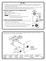
6. Connect the MLA VC10 Plus variable voltage ports to the
amplifier:
z Connect the ground (G) terminal of the MLA VC10 Plus to
the ground (Gnd) terminal of the amplifier.
z Connect the control signal voltage (+) terminal of the
MLA VC10 Plus to the signal voltage (Vc) terminal of the
amplifier.
7. Connect the RS-232 controller (see page 4) and power (see
page 5).
Extron USA Headquarters
+800.633.9876 (Inside USA/Canada Only)
Extron USA - West Extron USA - East
+1.714.491.1500 +1.919.850.1000
+1.714.491.1517 FAX +1.919.850.1001 FAX
Extron Europe
+800.3987.6673 (Inside Europe Only)
+31.33.453.4040
+31.33.453.4050 FAX
Extron India
1800.3070.3777 (Inside India Only)
+91-80 3055.3777
+91 80 3055 3737 FAX
Extron Japan
+81.3.3511.7655
+81.3.3511.7656 FAX
Extron China
+4000.EXTRON
+4000.398766
Inside China Only
+86.21.3760.1568
+86.21.3760.1566 FAX
Extron Asia
+800.7339.8766
Inside Asia Only
+65.6383.4400
+65.6383.4664 FAX
Extron Middle East
+971.4.2991800
+971.4.2991880 FAX
Extron Korea
+82.2.3444.1571
+82.2.3444.1575 FAX
© 2012 Extron Electronics All rights reserved. www.extron.com
GND Vc
+10V
+ to Vc
G to GND
Extron
MLA VC10 Plus
V-DC
G
Amplifier
  • Page 1 1
  • Page 2 2
  • Page 3 3
  • Page 4 4
  • Page 5 5
  • Page 6 6

Extron electronics MLA-VC10 User manual

Category
Power supply units
Type
User manual
This manual is also suitable for

Ask a question and I''ll find the answer in the document

Finding information in a document is now easier with AI