Page is loading ...

Installing and Maintaining
the C7004/C150 System

Notes, Cautions, and Warnings
NOTE: A NOTE indicates important information that helps you make better use of your computer.
CAUTION: A CAUTION indicates potential damage to hardware or loss of data if instructions are not
followed.
WARNING: A WARNING indicates a potential for property damage, personal injury, or death.
Information in this publication is subject to change without notice.
© 2014 Dell. All rights reserved.
Reproduction of these materials in any manner whatsoever without the written permission of Dell Inc. is strictly forbidden.
© 2014 Dell Inc.
Copyright © 2014 Dell Inc. All rights reserved. This product is protected by U.S. and international copyright and intellectual property laws. Dell and the Dell
logo are trademarks of Dell Inc. in the United States and/or other jurisdictions. All other marks and names mentioned herein may be trademarks of their respective
companies.
April 2014

Contents | 3
Contents
1 About this Guide
Information Symbols and Warnings . . . . . . . . . . . . . . . . . . . . . . . . . . . . . . . . . . . . . . 7
Related Documents. . . . . . . . . . . . . . . . . . . . . . . . . . . . . . . . . . . . . . . . . . . . . . . . . . . 8
2 Overview
C7004/C150 System Installation Process Overview. . . . . . . . . . . . . . . . . . . . . . . . . . 9
3 Preparing the Site
Site Selection Criteria . . . . . . . . . . . . . . . . . . . . . . . . . . . . . . . . . . . . . . . . . . . . . . . . 11
Preparing the Equipment Rack. . . . . . . . . . . . . . . . . . . . . . . . . . . . . . . . . . . . . . . . . 11
Power Requirements. . . . . . . . . . . . . . . . . . . . . . . . . . . . . . . . . . . . . . . . . . . . . . . . . 12
Shipping and Storing Components . . . . . . . . . . . . . . . . . . . . . . . . . . . . . . . . . . . . . . 12
4 Installing the C7004/C150 Chassis
Safety Considerations. . . . . . . . . . . . . . . . . . . . . . . . . . . . . . . . . . . . . . . . . . . . . . . . 15
Installing the Chassis into an Equipment Rack. . . . . . . . . . . . . . . . . . . . . . . . . . . . . 16
5 RPMs and Line Cards
Route Processor Modules. . . . . . . . . . . . . . . . . . . . . . . . . . . . . . . . . . . . . . . . . . . . . 19
RPM Label and LEDs . . . . . . . . . . . . . . . . . . . . . . . . . . . . . . . . . . . . . . . . . . . . 19
Line Cards. . . . . . . . . . . . . . . . . . . . . . . . . . . . . . . . . . . . . . . . . . . . . . . . . . . . . . . . . 20
Blank Panels. . . . . . . . . . . . . . . . . . . . . . . . . . . . . . . . . . . . . . . . . . . . . . . . . . . . . . . 20
Installing RPMs and Line Cards . . . . . . . . . . . . . . . . . . . . . . . . . . . . . . . . . . . . . . . . 21
Removing RPMs and Line Cards . . . . . . . . . . . . . . . . . . . . . . . . . . . . . . . . . . . . . . . 24
6 Management Cable Pinout
Connecting the Console Port . . . . . . . . . . . . . . . . . . . . . . . . . . . . . . . . . . . . . . . . . . 25
Cable and Adapter Pin Assignments . . . . . . . . . . . . . . . . . . . . . . . . . . . . . . . . . . . . 25
Accessing the Console with a DB-9 Adapter. . . . . . . . . . . . . . . . . . . . . . . . . . . 26
Accessing the Console with a DB-25 Adapter. . . . . . . . . . . . . . . . . . . . . . . . . . 26
7 AC Power Supply Units
Power Over Ethernet. . . . . . . . . . . . . . . . . . . . . . . . . . . . . . . . . . . . . . . . . . . . . . . . . 31
. . . . . . . . . . . . . . . . . . . . . . . . . . . . . . . . . . . . . . . . . . . . . . . . . . . . . . . . . . . . . . . . . 32
7 Installing Power Supply Units

4 | Contents
www.dell.com | support.dell.com
Removing AC Power Supply Units . . . . . . . . . . . . . . . . . . . . . . . . . . . . . . . . . . . . . . 33
Power Cord Requirements. . . . . . . . . . . . . . . . . . . . . . . . . . . . . . . . . . . . . . . . . 34
8 Installing DC Power Entry Modules
Recommended Normal Operating Conditions . . . . . . . . . . . . . . . . . . . . . . . . . . . . . 35
Redundancy . . . . . . . . . . . . . . . . . . . . . . . . . . . . . . . . . . . . . . . . . . . . . . . . . . . . . . . 35
Cable and Connector Requirements. . . . . . . . . . . . . . . . . . . . . . . . . . . . . . . . . . . . . 35
Installing a DC PEM . . . . . . . . . . . . . . . . . . . . . . . . . . . . . . . . . . . . . . . . . . . . . . . . . 36
Status LED . . . . . . . . . . . . . . . . . . . . . . . . . . . . . . . . . . . . . . . . . . . . . . . . . . . . . . . . 39
Removing a DC PEM . . . . . . . . . . . . . . . . . . . . . . . . . . . . . . . . . . . . . . . . . . . . . . . . 39
9 Powering Up
10 Fan Tray
Installing the Fan Tray. . . . . . . . . . . . . . . . . . . . . . . . . . . . . . . . . . . . . . . . . . . . . . . . 46
Removing the Fan Tray. . . . . . . . . . . . . . . . . . . . . . . . . . . . . . . . . . . . . . . . . . . . . . . 46
Fan Speed . . . . . . . . . . . . . . . . . . . . . . . . . . . . . . . . . . . . . . . . . . . . . . . . . . . . . 46
11 Removing and Replacing Components
Removing and Replacing the Fan Tray. . . . . . . . . . . . . . . . . . . . . . . . . . . . . . . . . . . 47
Removing and Replacing Power Supply Units . . . . . . . . . . . . . . . . . . . . . . . . . . . . . 48
Removing and Replacing a Line Card . . . . . . . . . . . . . . . . . . . . . . . . . . . . . . . . . . . 49
Removing and Replacing an RPM . . . . . . . . . . . . . . . . . . . . . . . . . . . . . . . . . . . . . . 49
12 System Boot
Booting from the BOOT_USER Prompt . . . . . . . . . . . . . . . . . . . . . . . . . . . . . . . . . . 51
13 The Compact Flash Card
Inserting the Compact Flash Card . . . . . . . . . . . . . . . . . . . . . . . . . . . . . . . . . . . . . . 55
Removing the Compact Flash Card . . . . . . . . . . . . . . . . . . . . . . . . . . . . . . . . . . . . . 55
Formatting the Compact Flash Card. . . . . . . . . . . . . . . . . . . . . . . . . . . . . . . . . . . . . 56
Alarms
AC Power Supplies and Alarms . . . . . . . . . . . . . . . . . . . . . . . . . . . . . . . . . . . . . . . . 58
B System Specifications
Physical Design. . . . . . . . . . . . . . . . . . . . . . . . . . . . . . . . . . . . . . . . . . . . . . . . . . . . . 59
Component Power Requirements. . . . . . . . . . . . . . . . . . . . . . . . . . . . . . . . . . . . . . . 62
Agency Compliance . . . . . . . . . . . . . . . . . . . . . . . . . . . . . . . . . . . . . . . . . . . . . . . . . 63
Safety Standards and Compliance Agency Certifications. . . . . . . . . . . . . . . . . . . . . 65
Electromagnetic Compatibility (EMC) . . . . . . . . . . . . . . . . . . . . . . . . . . . . . . . . 65

Contents | 5
Product Recycling and Disposal . . . . . . . . . . . . . . . . . . . . . . . . . . . . . . . . . . . . 65
Contacting Technical Support
The iSupport Website . . . . . . . . . . . . . . . . . . . . . . . . . . . . . . . . . . . . . . . . . . . . . . . . 67
Accessing iSupport Services . . . . . . . . . . . . . . . . . . . . . . . . . . . . . . . . . . . . . . . 67
Contacting the Technical Assistance Center . . . . . . . . . . . . . . . . . . . . . . . . . . . . . . 67
Locating Serial Numbers . . . . . . . . . . . . . . . . . . . . . . . . . . . . . . . . . . . . . . . . . . 68
Requesting a Hardware Replacement . . . . . . . . . . . . . . . . . . . . . . . . . . . . . . . . . . . 68

6 | Contents
www.dell.com | support.dell.com

About this Guide | 7
1
About this Guide
This guide provides site preparation recommendations and instructions for installing the Dell Networking
C7004/C150 chassis, fan tray, power supply units (PSUs), route processor modules (RPMs), and line
cards.
The C-series system is packaged with all of the necessary components, including slot blanks for RPMs,
power supplies, and line cards.
Information Symbols and Warnings
The following graphic symbols are used in this document to bring attention to hazards that exist when
handling the C7004/C150 and its components. Please read these alerts and heed their warnings and
cautions.
Table 1-1
describes symbols contained in this guide.
WARNING: The installation of this equipment shall be performed by trained and qualified personnel only.
Read this guide before installing and powering up this equipment. This equipment contains two AC power
cords. Disconnect both power cords before servicing.
WARNING: Class 1 laser product.
ATTENTION: Produit laser de classe 1
WARNUNG: Laserprodukt der Klasse 1
WARNING: This equipment contains optical transceivers, which comply with the limits of Class 1 laser
radiation. Visible and invisible laser radiation may be emitted from the aperture of the optical transceiver ports
when no cable is connected. Avoid exposure to laser radiation and do not stare into open apertures.
Table 1-1. Information Symbols
Symbol Warning Description
Note This symbol informs you of important operational information.
Caution This symbol informs you that improper handling and installation could result in equipment damage
or loss of data.
Warning This symbol signals information about hardware handling that could result in injury.

8 | About this Guide
www.dell.com | support.dell.com
WARNING: Building Supply Notice for AC Power Supply Use: This product relies on the building's installation
for short-circuit (overcurrent) protection. Ensure that a fuse or circuit breaker no larger than 120 VAC, 15A
U.S. (240 VAC, 10A international) is used on the phase conductors (all current-carrying conductors).
ATTENTION: Pour ce qui est de la protection contre les courts-circuits (surtension), ce produit dépend de
l'installation électrique du local. Vérifier qu'un fusible ou qu'un disjoncteur de 120 V alt., 15 A U.S. maximum
(240 V alt., 10 A international) est utilisé sur les conducteurs de phase (conducteurs de charge).
WARNUNG:Dieses Produkt ist darauf angewiesen, daß im Gebäude ein Kurzschluß- bzw.
Überstromschutz installiert ist. Stellen Sie sicher, daß eine Sicherung oder ein Unterbrecher von nicht mehr
als 240 V Wechselstrom, 10 A (bzw. in den USA 120 V Wechselstrom, 15 A) an den Phasenleitern (allen
stromführenden Leitern) verwendet wird.
WARNING: Building Supply Notice for DC Power Supply Use: An external disconnect must be provided and
be easily accessible. Dell Networking recommends the use of a 60A circuit breaker.
ATTENTION: Un interrupteur externe doit être fournis et doit être facilement accessible. Dell Networking
recommande l'utilisation d'un disjoncteur de 60Ampères.
WARNUNG: Eine leicht zugängliche Tren Dell Networking nvorrichtung muss in der Verdrahtung eingebaut
sein. Dell Networking empfiehlt einen 60A Sicherungsautomaten zu benutzen.
CAUTION: Wear grounding wrist straps when handling this equipment to avoid ESD damage.
CAUTION: Earthing (AKA grounding) connection essential before connecting supply. Always make the
ground connection first and disconnect it last.
CAUTION: Disposal of this equipment should be handled according to all national laws and regulations. See
Product Recycling and Disposal on page 65
.
CAUTION: This unit has more than one power supply connection; all connections must be removed to
remove all power from the unit.
ATTENTION: Cette unité est équipée de plusieurs raccordements d'alimentation. Pour supprimer tout courant
électrique de l'unité, tous les cordons d'alimentation doivent être débranchés.
WARNUNG: Diese Einheit verfügt über mehr als einen Stromanschluß; um Strom gänzlich von der Einheit
fernzuhalten, müssen alle Stromzufuhren abgetrennt sein.
CAUTION: Lithium Battery Notice: Danger of explosion if battery is replaced with incorrect type. Replace only
with the same type recommended by the manufacturer. Dispose of used batteries according to the
manufacturer's instructions.
ACHTUNG: Explosionsgefahr wenn die Battery in umgekehrter Polarität eingesetzt wird. Nur miteinem
gleichen oder ähnlichen, vom Hersteller empfohlenen Typ, ersetzen. Verbrauchte Batterien müssen per den
Instructionen des Herstellers verwertet werden.
ATTENTION: Il y a danger d'explosion s'il a remplacement incorrect de la batterie. Remplacer uniquement
avec une batterie du meme type ou d'un type equivalent recommande par le constructeur. Mettre au rebut les
batteries usagees conformement aux instructions du fabricant.
NOTE: Other cautionary statements appear in context elsewhere in this book.
Related Documents
For information about the Dell Networking OS, refer to the following documents:
• Dell Networking OS Command Reference for C-Series
• Dell Networking OS Configuration Guide for C-Series

Overview | 9
2
Overview
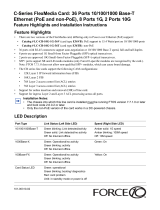
The C7004/C150 is a high performance switch/router. This 6-slot system contains two slots for Route
Processor Modules (RPMs) and four slots for line cards (
Figure 2-1
).
Figure 2-1. C7004/C150 Chassis (Front View)
C7004/C150 System Installation Process Overview
The Dell Networking recommended installation process is summarized below.
Table 2-1. C7004/C150 Component Requirements
Component Minimum Maximum Field-Replaceable
Backplane (factory installed) 1 1 No
Fan tray 1 1 Yes
RPM 1 2 Yes
Line card 1 4 Yes
AC Power Supply 1 6 Yes
Step Task Relevant Section in the Manual
1 Prepare the site.
Site Selection Criteria on page 11
2 Unpack the chassis and components.
Shipping and Storing Components on page 12
BLNK
Reset
RJ-45
Console
Compact Flash
Status Master
SFM
ACTIVE
Alarm
Reset
RJ-45
Console
Compact Flash
Status Master
SFM
ACTIVE
Alarm
BLNK
0
1
2
3
R0
R1
Power Supply Unit
Fan Tray
Front Mount Bracket
8
-Port 10G Fiber Line Card
Route Processor
Module
Line Card Blank
Power Supply
Unit Blank
48-Port 1G Line Ca
rd

10 | Overview
www.dell.com | support.dell.com
3 Install the chassis in a rack.
Installing the Chassis into an Equipment Rack on page 16
4 Install the fan tray.
Fan Tray on page 45
5 Install the RPMs and line cards.
RPMs and Line Cards on page 19
6 Connect console and management cables.
Management Cable Pinout on page 25
7 Install the power supplies.
AC Power Supply Units on page 29
8 Switch on all of the power supplies.
Powering Up on page 41
Step Task Relevant Section in the Manual

Preparing the Site | 11
3
Preparing the Site
Site Selection Criteria
Before beginning the installation process, make sure that the area where you intend to install your C7004/
C150 meets the following safety requirements:
• It is in a restricted access area.
• It is in a dry, clean, well-ventilated, temperature-controlled room, that is away from heat sources such as
hot air vents or direct sunlight.
• It is away from sources of severe electromagnetic noise.
• It is near an adequate power source.
• The AC power supply cord is used as the main disconnect device; ensure that the socket outlet is
located/installed near the equipment and is easily accessible.
• Connect the C7004/C150 to the appropriate branch circuit protection, as defined by local
electrical codes.
• It is positioned in a rack with adequate space in the front, rear, and sides of the unit for proper
ventilation, access to cables, and maintenance access.
• Allow at least six inches (16 cm) of clearance around the side intake and exhaust vents.
• Allow at least 12 inches (30.5 cm) between two C7004/C150s or a C7004/C150 and another side
airflow chassis.
• Allow at least 18 inches in the front and rear of the rack.
NOTE: The C-Series does not have an air filter, so take special care in making sure that the installation site
and the chassis itself are cleaned regularly.
Preparing the Equipment Rack
When you prepare your equipment rack:
• Make sure that the rack is bolted to the floor and braced to a wall or ceiling.
• Make sure that the rack is permanently grounded to earth ground. The equipment rack must be grounded
to the same ground point used by the power service in your area.
• The AC power cord is the primary ground.
When you install the chassis, use a level to ensure that the chassis is installed level.

12 | Preparing the Site
www.dell.com | support.dell.com
Power Requirements
There are two types of power supplies: Power Supply 1200W-AC and Power Supply 1600W-AC. The
minimum and the redundant power supplies required to operate is listed in the table below. Dell
Networking recommends the redundancy configuration.
The C7004/C150 needs at least one power supply to operate. However, Dell Networking recommends a
one-plus-one redundancy configuration. That is, use a minimum of two AC or DC power supplies; one is
for redundancy.
The C7004/C150 power requirements are given below:
Shipping and Storing Components
If you do not install your C7004/C150 system and components immediately, Dell Networking
recommends you properly store components (including all extra field-replaceable parts) until you are
ready to install them.
Follow these indoor storage guidelines:
• Storage temperature should remain constant ranging from -40°F to 158°F (-40°C to 70°C).
• Non-condensing relative humidity should be maintained with 5 to 95%.
• Store on a dry floor, away from direct sunlight, heat, and air conditioning ducts.
• Store in a dust-free environment.
Voltage Minimum PSUs
Minimum with
Redundant PSUs
Power Supply 1200W-AC/Power Supply
1600W-AC
100-120 1 2
Power Supply 1200W-AC 200-240 1 2
Power Supply 1600W-AC 200-240 1 2
Table 3-1. System Specifications
Parameter Specifications
Nominal Input Voltage 100-240 V 50/60 Hz
Maximum AC Power Supply Input Current
(Based on 1200 W output for 100/120 V and
1600 W 200/240 V lines)
14 A @ 100 V per AC Power Supply
11 A @ 120 V per AC Power Supply
9 A @ 200 V per AC Power Supply
7 A @ 240 V per AC Power Supply
Maximum System Power Input 6,897 KVA @ 100/120 V
7,315 KVA @ 200/240 V
Maximum Thermal Output at 100/120V 5,618 BTU/hour
Maximum Thermal Output at 200/240V 5,304 BTU/hour

Preparing the Site | 13
Save the protective packaging in which your line cards, RPMs, power supplies, and fan tray arrived. The
packaging can be used in case you experience trouble with a component and must return it to Dell
Networking. Place the components in their original protective shipping packaging and original shipping
position.
NOTE: Do not transport the chassis with the components (line cards, power supplies, and RPMs) installed.
Place the components in their original protective shipping packaging and original shipping position. Shipping
components installed in the chassis or without their protective packaging, might damage the components or
the backplane.

14 | Preparing the Site
www.dell.com | support.dell.com

Installing the C7004/C150 Chassis | 15
4
Installing the C7004/C150 Chassis
Safety Considerations
NOTE: Use an equipment lift or pallet jack when lifting or moving the chassis. Install the chassis into the rack
before inserting chassis components. Lift the C7004/C150 chassis only from the bottom. Lifting by the chassis
shelves or power supply openings might damage the chassis.
WARNING: To prevent bodily injury when mounting or servicing this unit in a rack, you must take special
precautions to ensure that the system remains stable. The following guidelines are provided to ensure your
safety:
• This unit should be mounted at the bottom of the rack if it is the only unit in the rack.
• When mounting this unit in a partially filled rack, load the rack from the bottom to the top with the heaviest
component at the bottom of the rack.
• If the rack is provided with stabilizing devices, install the stabilizers before mounting or servicing the unit in
the rack.
ATTENTION: Pour éviter toute blessure corporelle pendant les opérations de montage ou de réparation de
cette unité en casier, il convient de prendre des précautions spéciales afin de maintenir la stabilité du
système. Les directives ci-dessous sont destinées à assurer la protection du personnel:
• Si cette unité constitue la seule unité montée en casier, elle doit être placée dans le bas.
• Si cette unité est montée dans un casier partiellement rempli, charger le casier de bas en haut en plaçant
l'élément le plus lourd dans le bas.
• Si le casier est équipé de dispositifs stabilisateurs, installer les stabilisateurs avant de monter ou de
réparer l'unité en casier.
WARNUNG: Zur Vermeidung von Körperverletzung beim Anbringen oder Warten dieser Einheit in einem
Gestell müssen Sie besondere Vorkehrungen treffen, um sicherzustellen, daß das System stabil bleibt. Die
folgenden Richtlinien sollen zur Gewährleistung Ihrer Sicherheit dienen:
• Wenn diese Einheit die einzige im Gestell ist, sollte sie unten im Gestell angebracht werden.
• Bei Anbringung dieser Einheit in einem zum Teil gefüllten Gestell ist das Gestell von unten nach oben zu
laden, wobei das schwerste Bauteil unten im Gestell anzubringen ist.
• Wird das Gestell mit Stabilisierungszubehör geliefert, sind zuerst die Stabilisatoren zu installieren, bevor
Sie die Einheit im Gestell anbringen oder sie warten.

16 | Installing the C7004/C150 Chassis
www.dell.com | support.dell.com
Installing the Chassis into an Equipment Rack
Follow these steps to install the chassis into a 19-inch equipment rack:
Step Task
1 Dell Networking recommends that you install a equipment rack bar. This bar enables you to easily position the
chassis into the rack and stabilizes the chassis.
• Orient the equipment rack bar at the desired location in the rack, with the arrows pointing up and the smooth
side facing outward.
Figure 4-1. Installing the Equipment Rack Bar
2 Attach the bar to the rack (
Figure 4-1
) using the mounting screws provided with your rack.
3 Use an equipment lift to align the chassis rack-mount holes with the equipment rack holes, and situate the chassis
on top of the equipment rack bar.


18 | Installing the C7004/C150 Chassis
www.dell.com | support.dell.com

RPMs and Line Cards | 19
5
RPMs and Line Cards
The C7004/C150 system accommodates four line cards and two Route Processor Modules (RPMs).
Route Processor Modules
The C7004/C150 system requires the installation of at least one RPM; two are recommended.
• One RPM provides each line card with 48 Gigabits of backplane bandwidth.
• Two RPMs provides each line card with 96 Gigabits of backplane bandwidth.
RPMs can be installed in either the R0 or R1 slot as shown in
Figure 2-1 on page 9
. Do not force RPMs
into card slots. RPMs are keyed differently than line cards to prevent improper installation.
The RPM must be running Dell Networking OS version 7.6.1.0 or later.
NOTE: RPMs are hot-swappable. High Availability is supported.
NOTE: If your system contains two RPMs, both RPMs must have the same software image.
NOTE: RPMs are interchangeable between the C7008/C300 and the C7004/C150 only if they are running
Dell Networking OS version 7.6.1.0 or later.
RPM Label and LEDs
NOTE: RPMs are hot-swappable. High Availability is supported.
Table 5-1
describes the RPM LED states and the RPM front panel.
Table 5-1. RPM Front Panel and LED Descriptions
Section Label Description
Management Console Port Use this RJ-45 jack for the initial system boot, as well as system configuration and
monitoring. A modem connection is not available.
10/100/1000
Ethernet
Use this non-routable Ethernet port to download images and manage the system. FTP and
Telnet operations are supported. This port is an RJ-45.
Port LEDs:
Link/Activity:
Blinking Amber: 100M speed
Solid Amber: 1G speed
Off: 10M speed
Speed:
Blinking Green: Link detected/ Activity
Solid Green: Link detected/ No Activity
Off: No Link/ Card Offline

20 | RPMs and Line Cards
www.dell.com | support.dell.com
Line Cards
Line cards are hot-swappable. Any line card can be inserted into any line card slot. Line card slots are
numbered 0 to 3; the number label is on the fan tray. The LC-CB-GE-48P and LC-CB-10GE-8P line
cards can only be installed in a chassis running Dell Networking OS version 7.6.1.0 or later.
NOTE: The LC-CB-GE-48P and LC-CB-10GE-8P line cards are interchangeable between the C7008/C300
and C7004/C150 only if the chassis is running Dell Networking OS version 7.6.1.0 or later.
Line card LEDs are described in the documentation specific to each line card. Refer to the installation
documentation that came with the card for to understand LED appearance and meaning.
Blank Panels
Blanks are required in empty slots to control airflow for adequate system cooling, personal safety, and
EMI containment during operation.
The blank panels do not have board components or connector pins. Align the blank with the guides and
gently slide toward the backplane (
Figure 5-5
and
Figure 5-6
).
NOTE: All chassis slots must be installed with operational modules or blanks. Always replace cards and blank
panels immediately.
Alarm LED Red: Major Alarm—a critical condition exists (such as a severe over-temperature condition).
See
Appendix , Alarms, on page 57
for more information.
Flashing red: Minor Alarm—a serious condition exists (such as a single fan failure or a line
card failure). See
Appendix , Alarms, on page 57
for more information.
Unlit: No alarm conditions.
Flash Slot Use the compact flash card (external compact flash memory card) slot to store and retrieve
boot and system images.
In Use LED Green: The flash memory card is in the process of a read or write process. Do not remove the
flash card when the In Use LED is lit.
Unlit: Not in use
Master LED Indicates that this RPM is the Primary RPM
Green: Primary
Unlit: Secondary/ fatal error/ booting
Reset Button Use this recessed reset switch to reset the RPM by inserting a small object, such as a pen tip,
to depress the button.
SFM Active Green: Switch Fabric is active
Unlit: Switch Fabric is inactive
Status LED Green: Operational
Red: Card problem state
Flashing green: Booting/ diagnostics
Unlit: In standby mode, or power is off
Table 5-1. RPM Front Panel and LED Descriptions (continued)
Section Label Description
/