
Model 12630
Telescopic Crane
Owner’s Manual
Stellar Industries, Inc.
190 State Street
PO Box 169
Garner, IA 50438
800-321-3741
Fax: 641-923-2811
www.stellarindustries.com
Subject to Change without Notication.
© 2016 Stellar Industries, Inc. Last Revision: 02/01/16
Installation • Assembly Drawings • Parts
Notice: A copy of this manual must remain with the equipment at all times.
For a printable download copy, please visit: www.stellarindustries.com
®
TM
Plus

Page ii | Stellar® 12630 Telescopic Crane Owner’s Manual
Model 12630 Manual Revisions
MODEL NO.SERIAL NO.
DATE
MADE IN THE U.S.A. BY STELLAR INDUSTRIES, INC.
PN C5942
®
PATENT INFORMATION
http://www.stellarindustries.com/ip
MODEL NO.SERIAL NO.
DATE
MADE IN THE U.S.A. BY STELLAR INDUSTRIES, INC.
PN C5942
®
PATENT INFORMATION
http://www.stellarindustries.com/ip
Serial Tag
Location
Date of Revsion Section Revised Description of Revision
3/23/15 Chapter 3:
Assembly Drawings
New Base, Gear Bearing, Mast
Assemblies.

Stellar® 12630 Telescopic Crane Owner’s Manual | Page iii
Table of Contents
Introduction .........................................................................................................iv
Chapter 1 - Specications ..................................................................................... 1
Model 12630 Specications ...............................................................................1
Capacity Chart - Decal PN 71161 .....................................................................2
Dimensional Drawing 1 .......................................................................................3
Dimensional Drawing 2 .......................................................................................4
Chapter 2 - Installation .......................................................................................... 5
General Installation .............................................................................................5
Installer Notice ...................................................................................................5
Torque Data Chart ............................................................................................6
Installation Overview ........................................................................................7
Control Kit - PN 75051 ..........................................................................................8
Electrical Circuit Grounding ...............................................................................9
Hydraulic Kit - PN 72759 ....................................................................................10
Valve Bank - PN 52265 .......................................................................................11
Hydraulic Installation .........................................................................................12
Winch Case Drain Installation ..........................................................................13
Hydraulic System ...............................................................................................14
Face Seal/O-Ring Size Chart ............................................................................15
Stability Procedure ............................................................................................16
Crane Load Level Indicator .............................................................................17
Decal Kit - PN 71159 ..........................................................................................18
Chapter 3 - Assembly Drawings ......................................................................... 19
Base Assembly - PN 71166 ................................................................................19
Gear Bearing - PN 71041 ..................................................................................20
Mast Assembly - PN 70807 ................................................................................21
Winch - PN 57920 ...............................................................................................22
Main Boom Assembly - PN 70806 .....................................................................23
Extension Boom Assembly - PN 75100 .............................................................24
Main Cylinder Assembly - PN 71162 ................................................................25
Extension Cylinder Assembly - PN 71455 .........................................................26
Snatch Block Assembly - PN 55898 ..................................................................27

Page iv | Stellar® 12630 Telescopic Crane Owner’s Manual
Introduction
A copy of this manual is provided with every crane and can be found in the hard plastic
manual case that is installed on the chassis. A copy of this manual shall remain with the
crane at all times.
Throughout the manual, three signal words will be used to bring attention to important
items:
A NOTICE signal word indicates a practice not related to physical injury.
A WARNING signal word indicates a hazardous situation which, if not
avoided, could result in death or serious injury.
A DANGER signal word indicates a hazardous situation which, if not
avoided, will result in death or serious injury.
Information contained within this manual does not cover operation, maintenance, or
troubleshooting. Please refer to the General Light Duty Crane Manual for details on these
items.
This manual is not binding. Stellar Industries, Inc. reserves the right to change, at any
time, any or all of the items, components, and parts deemed necessary for product
improvement or commercial/production purposes. This right is kept with no requirement or
obligation for immediate mandatory updating of this manual.
In closing:
If more information is required or technical assistance is needed, or if you feel that any
part of this manual is unclear or incorrect, please contact the Stellar Customer Service
Department by phone at 800-321-3741 or email at [email protected].
WARNING
NOTICE
DANGER
For Technical Questions, Information, Parts, or Warranty, Call Toll-Free at
800-321-3741
Hours: Monday - Friday, 8:00 a.m. - 5:00 p.m. CST
Or email at the following addresses:
Technical Questions, and Information [email protected]
Order Parts [email protected]
Warranty Information [email protected]

Stellar® 12630 Telescopic Crane Owner’s Manual | Page 1
Model 12630 Crane
Specifications Sheet
Page: 1 of 4
Crane Rating*:
77,800 ft-lbs (10.76 TM)
Standard Boom Length:
13' 4" (4.06 m) from CL of Crane
Boom Extension:
Hydraul
ic 100" (254 cm)
Hydraulic 100" (254 cm)
Maximum Horizontal Reach:
30' (9.14 m) from CL of Crane
Maximum Vertical Lift:
31' 9" (9.68 m) from Crane Base
Stowed Height (Crane Only):
37.75" (95.5 cm)
Required Mounting
Space:
20"
x 21" (50.8 cm x 53.3 cm)
Approximate Crane Weight:
Controls:
Radio control standard for all functions.
Wire Rope:
7/16"
(1.11 cm) 6X19 IWRC-DGXXIP X 120' (36.58 m)
Boom Elevation:
-10º to +80º
Line Pull Speed:
55 ft/min (16.76 m/min)
Max. Single Part Line:
6,000 lbs (2,720 kg)
Max. Double Part Line:
12,000 lbs (5,440 kg)
Rotation (Worm Gear):
400º Power
Lifting Capacity**:
12,000 lbs @ 6' 5" (5,440 kg @ 1.97 m)
2,590
lbs @ 30' (1,175 kg @ 9.14 m)
Power Supply:
2,580 lbs (1,170 kg)
12630 Standard
1st Stage:
2nd Stage:
PTO & Pump:
8 gpm @ 3,000 psi
(30.3
lpm @ 207 bar)
Winch Specifications
*Crane rating in Boost Mode. Normal crane rating is 66,000 ft-lbs (9.13 TM).
**Maxim
um capacities in Boost Mode.
Chapter 1 - Specications
Model 12630 Specications

Page 2 | Stellar® 12630 Telescopic Crane Owner’s Manual
Model 12630 Crane
Specifications Sheet
Page: 2 of 4
Crane Rating*:
Standard Boom Length:
Boom Extension:
Maximum Horizontal Reach:
Maximum Vertical Lift:
Stowed Height (Crane Only):
Required Mounting Space:
Approximate Crane Weight:
Controls:
Wire Rope:
Boom Elevation:
Line Pull Speed:
Max. Single Part Line:
Max. Double Part Line:
Rotation (Worm Gear):
Lifting Capacity**:
Power Supply:
1st Stage:
2nd Stage:
Winch Specifications
PN 71161 - Rev A
0’
2.4 m1.8 m1.2 m0.6 m
2’ 4’ 6’ 8’
3.1 m
10’
3.7 m
12’
4.3 m
14’
4.9 m
16’
5.5 m
18’
6.1 m
20’
6.7 m
22’
7.3 m
24’
7.9 m
26’
8.5 m
28’
13’4”
4.06 m
21’8”
6.60 m
30’
9.14 m
-10º
80º
0º
15º
30º
45º
60º
2.4 m
1.8 m
6’
8’
3.1 m
10’
3.7 m
12’
4.3 m
14’
4.9 m
16’
5.5 m
18’
6.1 m
20’
6.7 m
22’
7.3 m
24’
7.9 m
26’
8.5 m
28’
9.8 m
32’
10.4 m
34’
9.1 m
30’
0'
12000 lbs
5445 kg
12000 lbs
5445 kg
12000 lbs
5445 kg
9900 lbs
4490 kg
7000 lbs
3175 kg
5715 lbs
2590 kg
4950 lbs
2245 kg
3045 lbs
1380 kg
2200 lbs
1000 kg
4400 lbs
1995 kg
3110 lbs
1410 kg
2540 lbs
1150 kg
2275 lbs
1030 kg
3150 lbs
1430 kg
3515 lbs
1595 kg
4305 lbs
1950 kg
6090 lbs
2760 kg
11670 lbs
5295 kg
8250 lbs
3740 kg
6735 lbs
3055 kg
5835 lbs
2645 kg
5025 lbs
2280 kg
5925 lbs
2690 kg
3090 lbs
1400 kg
3645 lbs
1655 kg
2230 lbs
1010 kg
2630 lbs
1190 kg
3590 lbs
1630 kg
2590 lbs
1175 kg
3715 lbs
1685 kg
2680 lbs
1215 kg
4145 lbs
1880 kg
2990 lbs
1355 kg
5075 lbs
2300 kg
3665 lbs
1660 kg
7180 lbs
3256 kg
5185 lbs
2350 kg
5125 lbs
2325 kg
6040 lbs
2740 kg
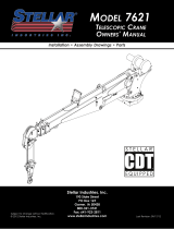
Weight of load handling devices are
part of the load lifted and must be
deducted from the capacity.
Maximum 1 - part line capacity is
6000 lbs (2720 kg). For greater
loads, use 2 - part line.
Boost
(If Equipped)
Standard
Capacity Chart - Decal PN 71161

Stellar® 12630 Telescopic Crane Owner’s Manual | Page 3
Model 12630 Crane
Specifications Sheet
Page: 3 of 4
Crane Rating*:
Standard Boom Length:
Boom Extension:
Maximum Horizontal Reach:
Maximum Vertical Lift:
Stowed Height (Crane Only):
Required Mounting Space:
Approximate Crane Weight:
Controls:
Wire Rope:
Boom Elevation:
Line Pull Speed:
Max. Single Part Line:
Max. Double Part Line:
Rotation (Worm Gear):
Lifting Capacity**:
Power Supply:
1st Stage:
2nd Stage:
Winch Specifications
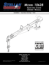
31'10"
9.70m
23'8"
7.21m
15'5"
4.70m
3'5"
1.04m
0.54m
1'9"
6'4"
1.93m
13'3"
4.04m 21'7"
6.58m 29'11"
9.12m
1.47m
4'10"
1'1"
0.33m
Dimensional Drawing 1

Page 4 | Stellar® 12630 Telescopic Crane Owner’s Manual
Model 12630 Crane
Specifications Sheet
Page: 4 of 4
Crane Rating*:
Standard Boom Length:
Boom Extension:
Maximum Horizontal Reach:
Maximum Vertical Lift:
Stowed Height (Crane Only):
Required Mounting Space:
Approximate Crane Weight:
Controls:
Wire Rope:
Boom Elevation:
Line Pull Speed:
Max. Single Part Line:
Max. Double Part Line:
Rotation (Worm Gear):
Lifting Capacity**:
Power Supply:
1st Stage:
2nd Stage:
Winch Specifications
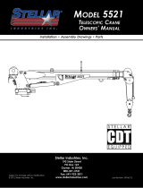
13'-3"
[ 4.03m ]
12.19in
0.31m
52.73in
1.34m
20.29in
0.52m
42.00in
1.07m
24.54in
0.62m
CG
0.98m
38.57in
14'-11"
[ 4.54m ]
Dimensional Drawing 2

Stellar® 12630 Telescopic Crane Owner’s Manual | Page 5
Installer Notice
According to Federal Law (49 cfr part 571), each nal-stage manufacturer shall complete
the vehicle in such a manner that it conforms to the standards in effect on the date of
manufacture of the incomplete vehicle, the date of nal completion, or a date between
those two dates. This requirement shall, however, be superseded by any conicting
provisions of a standard that applies by its terms to vehicles manufactured in two or more
stages.
Therefore, the installer of Stellar® Cranes and Bodies is considered one of the manufacturers
of the vehicle. As such a manufacturer, the installer is responsible for compliance with all
applicable federal and state regulations. They are required to certify that the vehicle is in
compliance with the Federal Motor Vehicle Safety Standards and other regulations issued
under the National Trafc and Motor Vehicle Safety Act.
Please reference the Code of Federal Regulations, title 49 - Transportation, Volume 5 (400-
999), for further information, or visit http://www.gpoaccess.gov/nara/index.html for the full
text of Code of Federal Regulations.
Chapter 2 - Installation
General Installation
This chapter is designed to serve as a general guide for the installation of a Stellar 12630
Crane on a Stellar Service Body. Each installation is considered unique so certain portions
of this chapter may or may not apply to your direct application. If a question should arise
during the installation process, please contact Stellar Customer Service at (800) 321 3741.
This crane is designed for use with a Stellar Service Body installed on a vehicle that meets
the minimum chassis requirements of the crane. It is the installer’s responsibility to assure
that the crane is mounted on a platform that will support the maximum crane rating of this
crane.
Do not install this crane on a body not capable of handling the loads
imposed on it. Failure to do so may result in serious injury or death.
When installing welder units to the service bodies, it is highly
recommended that a surge protector is installed on the chassis batteries to protect the
crane radio receiver, wiring and other electronic devices from an unexpected electrical
spike or surge. Failure to do so could result in extensive damage to the service body and
crane electrical circuit.
WARNING
NOTICE

Page 6 | Stellar® 12630 Telescopic Crane Owner’s Manual
When using the torque data in the
chart, the following rules should be
observed:
• Bolt manufacturer’s particular
specications should be consulted
when provided.
• Flat washers of equal strength
must be used.
• All torque measurements are
given in foot-pounds. To convert
to inch-pounds, multiply by 12.
• Torque values specied are for
bolts with residual oils or no special
lubricants applied. If special
lubricants of high stress ability,
such as Never-Seez compound
graphite and oil, molybdenum
disulphite, colloidal copper or white lead are applied, multiply the torque values in the
charts by the factor .90. The use of Loctite does not affect the torque values listed above.
• Torque values for socket-head capscrews are the same as for Grade 8 capscrews.
• Do not use these values if a different torque value or tightening procedure is given for
a specic application. Torque values listed are for general use only. Check tightness of
fasteners periodically.
• Shear bolts are designed to fail under predetermined loads. Always replace shear bolts
with identical grade.
• Fasteners should be replaced with the same or higher grade. If higher grade fasteners
are used, these should only be tightened to the strength of the original.
• Tighten plastic insert or crimped steel-type lock nuts to approximately 110 percent of the
dry torque values shown in the chart below, applied to the nut, not to the bolt head.
Tighten toothed or serrated-type lock nuts to the full torque value. Note: “Lubricated”
means coated with a lubricant such as engine oil, or fasteners with phosphate and oil
coatings. “Dry” means plain or zinc plated without lubrication. Tighten lubricated bolts
to approximately 80% of dry bolts.
Size Bolt DIA Plain Plated Plain Plated Plated
(DIA-TPI) (Inches) (Ft-Lb) (Ft-Lb) (Ft-Lb) (Ft-Lb) (Ft-Lb)
5/16-18 0.3125 17 13 25 18 22
3/8-16 0.3750 31 23 44 33 39
7/16-14 0.4375 49 37 70 52 63
1/2-13 0.5000 75 57 105 80 96
9/16-12 0.5625 110 82 155 115 139
5/8-11 0.6250 150 115 220 160 192
3/4-10 0.7500 265 200 375 280 340
7/8-9 0.8750 395 295 605 455 549
1-8 1.000 590 445 910 680 823
1 1/8-7 1.1250 795 595 1290 965 1167
1 1/4-7 1.2500 1120 840 1815 1360 1646
1 3/8-6 1.3750 1470 1100 2380 1780 2158
1 1/2-6 1.500 1950 1460 3160 2370 2865
GRADE 5 GRADE 8 GRADE 9
Torque Data Chart

Stellar® 12630 Telescopic Crane Owner’s Manual | Page 7
1. Determine that the mounting location for the 12630 crane is at least 20” x 21” (50.8 x 50.8
cm).
2. Use the detail below to drill 1.06” diameter holes into the mounting plate. Run tap on the
threads of the base to be sure they are clean.
3. Use a crane or lifting device capable of lifting the weight of the Stellar® Crane. The
Stellar® 12630 weighs approximately 2975 lbs (1350 kg). Note: cranes are shipped
with rotation positioned at 200 degrees of 400 degree system. This will allow for easy
installation of the crane and permanent connection of all hydraulic and electrical
components prior to repositioning into the crane saddle.
4. Connect straps or chain from the lifting device to the lifting rings on the Stellar 12630.
5. Use six (6) 3” x 1” #8 bolts and six (6) #8 at washers.
6. Install a washer on each bolt.
7. Apply Loctite Thread locker #277 to the bolts.
8. Using the lifting device, lower the Stellar® 12630 just above the crane compartment
and start the bolts. Have someone assist in leveling the crane. Note: the rotation motor
should be to the door side of crane compartment and the boom should be extended
back over the rear bumper.
9. Secure the crane using the mounting hardware provided. Note: longer or shorter cap
screws may be required – recommended thread engagement into crane base is 1.75” –
use grade 8, zinc plated cap screws only.
10. Torque the cap screws to 680 ft-lbs.
11. Remove supporting crane.
12. Hook-up hydraulics and electrical using the schematics provided in this chapter.
Installation Overview
2
1
FRONT
Motor
Hole Mounting Detail
Ø1.063
7.38
14.75
7.38
14.75
Ø6.00
4 Places
65382
ITEM NO. PART NO.
15199
QTY.
WASHER 1.00 SAE FLAT YELLOW GR8
CAP SCR 1.00X8X3.00 HHGR8 ZY
DESCRIPTION
4
4

Page 8 | Stellar® 12630 Telescopic Crane Owner’s Manual
PN 75051
RECEIVER - RADIO (PART OF 1)
RADIO CONTROLLER ASSEMBLY
VALVE CONTROL MODULE (PART OF 1)
TRANSMITTER - RADIO (PART OF 1)
INCLINOMETER
5
A2B
SWITCH
CORD REEL
POWER
CTRL OUTPUT
GROUND
ENG START
ENG STOP
CPRSR ON/OFF
SPEED CTRL
EXTENSION SENSOR
WIRE HARNESS CRANE CDT PLUS
4
CHASSIS
CAN BUSE LINK
CAN BUS
OPTION 1
DOCKING STATION RADIO TRANSMITTER
CTRL PWR JUMPER
3
INCLINOMETER 60 DEG PENNY AND GILES
SWITCH LIMIT E1161-B9111-6C
CORD REEL ASM 28/30 FT CRANE
SENSOR TAPE POSITION 6M CANOPEN
TRANSDUCER PRESSURE 5000 PSI
8
9
10
11
CABLE ASM BACKUP CDTPLUS MOD
E
FB
D
ECA
F
A
C
D
B
PD2
PD1
12121 2 12
12
1 21 21 2 1 2
A
B
2
MAIN CYL
MANIFOLD
PD1
PD2
BASE
ENDROD
END
7
21
12
OPTION 2
GROUND
IGN PWR SUPPLY
ROTROT
PROPORTIONAL
CW CCW
VALV E
MAIN
DOWN
EXT.
RETRACT
MAIN
UP
EXTE ND
WINCH
DOWN
WINCH
UP
EXT
6
DOCKING STATION
#1 / BLK SUPPLY (-)
#2 / RED SUPPLY (+) 12V/24V
#3 / GRN ALARM DISABLE GND INPUT
WHT OPTION OUTPUT
TRANSMITTER
RECEIVER
VCM
BATTERY RECHRG CDT PLUS (PART OF 1)
Control Kit - PN 75051
Any modication to the crane
control system (electrical and/or
hydraulic) must be approved by
Stellar.
NOTICE

Stellar® 12630 Telescopic Crane Owner’s Manual | Page 9
Electrical Circuit Grounding
When installing the crane, always locate a good source for grounding the circuit. A
majority of electrical failures are due to poor grounding. Poor grounding can cause
intermittent operation of the equipment, electrical component failures and cause the
equipment to not operate at all.
Chassis manufacturers usually will have a ground strap which ties into the truck frame
from the battery, but it is always a good idea to check each individual model to verify
where the ground is located. Never use the mechanic body as a ground source. Make
sure the electrical grounds are routed to either the chassis frame rail or the chassis’s main
grounding source.
Stellar provides a stud (PN 40992) for grounding the crane to the chassis frame rail:
• Drill the hole to the frame rail in accordance with the chassis body
builder’s guide.
• Hole size: 21/64”
• The hole location should allow for the shortest length of ground wire while keeping
enough slack for exibility.
• Be sure to grind the frame rail around the hole to ensure a proper ground connection.
• Frame rail thickness may require additional at washers (as shown).
• Use an electrical coating on hardware to prevent corrosion.
Inside Frame Rail Outside Frame Rail
WARNING

Page 10 | Stellar® 12630 Telescopic Crane Owner’s Manual
NOTE: USE 12" OF HOSE PROTECTOR
P/N 17288 OVER THE 3 WINCH HOSES
NOTE: USE 32" OF HOSE PROTECTOR
P/N 17288 OVER THE ROTATION HOSES
PN 72759
Hydraulic Kit - PN 72759

Stellar® 12630 Telescopic Crane Owner’s Manual | Page 11
PN 52265
NOTE: PN's 24960 & 25371 DO NOT INCLUDE COIL PN 44532
2
4
4
4
1
3
4
4
4
4
4
3
3
4
3
HYDRAULIC SCHEMATIC
YTQNOITPIRCSEDTRAPMETI
125367 RELIEF VALVE 24685/246901
25368 SEAL KIT 25367
224960 VALVE FLW CTRL PRP/JP04C3150N 0-81
25369 SEAL KIT 24960/25381
325371 VALVE SOLND 3 POS 4 WAY TA ND G045714
25373 SEAL KIT 25371/25372
444532 COIL 12VDC DUETSCH CAP012H9
Valve Bank - PN 52265

Page 12 | Stellar® 12630 Telescopic Crane Owner’s Manual
1. After mounting, locate the pressure and return
lines. Note: Pressure line is 3/8” hose; Winch
Case Drain Line is 3/8” hose; Return line is 1/2”
hose. Hoses are terminated using swivel fittings.
2. Install hydraulic lines per diagram below. See
next page for Case Drain Installation. Note:
Stabilizer valve supplies oil to crane using the
Power Beyond feature.
3. Install hydraulic reservoir with return filter. Attach
pump pressure line to valve, return link to tank.
4. Fill system with hydraulic oil (See Stellar®
Lubrication Recommendations for fluid details).
(Blue)
Stabilizer Functions
Stabilizer Functions
Typical Stabilizer Valve
with Power Beyond Capabilities
Follow the instructions presented
on this page. Failure to follow
these instructions may result in
death or serious injury.
WARNING
Hydraulic Installation

Stellar® 12630 Telescopic Crane Owner’s Manual | Page 13
Installing the winch case drain
1. The winch case drain must run directly to the reservoir to ensure no back pressure in the line.
2. Use 3/8” hydraulic hose and fittings rated for a minimum of 300 psi.
3.
4. Attach one end of the winch case drain to 3/8 swivel fitting located in step 3.
5. Route the winch case drain hose directly to the reservoir.
6. Connect the second end of the winch case drain to unshared fitting on the top of the reservoir as
shown in Fig 2.
Fig.1 Fig. 2
Locate the winch case drain line at the bottom of the crane base as shown in Fig. 1 (Blue Hose).
Note: Both the main pressure and winch case drane line use a 3/8” swivel fitting. Verify the winch
case drain is attached to the hose that is connected to the winch motor.
(Blue)
Follow the instructions presented
on this page. Failure to follow
these instructions may result in
death or serious injury.
WARNING
Winch Case Drain Installation

Page 14 | Stellar® 12630 Telescopic Crane Owner’s Manual
Hydraulic System

Stellar® 12630 Telescopic Crane Owner’s Manual | Page 15
Face Seal (A)
Stellar® PN
Hose
Size
Fitting
Size Stellar® PN
O-ring Boss (B)
#4 C2027 D1245
#6 C2028 D1246
#8 C2029 D1247
#10 32223 D1248
#12 D1244 D1249
#161”
3/4”
5/8”
1/2”
3/8”
1/4”
D1250
B
A
Face Seal/O-Ring Size Chart

Page 16 | Stellar® 12630 Telescopic Crane Owner’s Manual
Denition of Stability for the Stellar Telescopic Crane Products:
A truck is stable until the load cannot be lifted off the ground with the winch, without
tipping over the truck. Every Stellar crane installed must be tested for stability to determine
the actual load capacity of the nal truck package. The actual test data must be
recorded and supplied with the truck at the time of in-service and should be kept with
the truck at all times. The following procedure will test the truck package for stability and
will provide a stability capacity chart. The load limit information shown on the stability
capacity chart is formulated on 85% tipping.
Set Up:
1. Locate the truck on a test course in position for loading and engage travel brakes.
2. Set stabilizers so that they make contact with rm, level footing.
3. Operate the crane under partial load to assure operator prociency and proper
machine function.
4. Put the radio into Stability Test Mode:
A. Push the middle four crane function switches up and hold until all lights come on
(approximately 5 seconds.)
B. At this point,the crane will have enough capacity to handle the weight for the
stability test.
C. The radio will timeout of stability mode after 30 minutes or when the E-Stop button
is pushed.
Note: The radio can only be put into stability mode ve times. After that, the radio would
have to be returned to Stellar to be reprogrammed to allow additional stability testing. All
other radio functions will work properly even if stability mode is not available.
Stability Procedure
Page is loading ...
Page is loading ...
Page is loading ...
Page is loading ...
Page is loading ...
Page is loading ...
Page is loading ...
Page is loading ...
Page is loading ...
Page is loading ...
Page is loading ...
Page is loading ...
-
 1
1
-
 2
2
-
 3
3
-
 4
4
-
 5
5
-
 6
6
-
 7
7
-
 8
8
-
 9
9
-
 10
10
-
 11
11
-
 12
12
-
 13
13
-
 14
14
-
 15
15
-
 16
16
-
 17
17
-
 18
18
-
 19
19
-
 20
20
-
 21
21
-
 22
22
-
 23
23
-
 24
24
-
 25
25
-
 26
26
-
 27
27
-
 28
28
-
 29
29
-
 30
30
-
 31
31
-
 32
32


stellar labs 10621 Owner's manual
- Type
- Owner's manual
Ask a question and I''ll find the answer in the document
Finding information in a document is now easier with AI
Related papers
Other documents
-
 KVH TracPhone Fleet One, FB250 & FB150 Installation guide
-
 Ultra-tow Hydraulic Pickup Truck Crane Owner's manual
-
 Ultra-tow Pickup Truck Crane Owner's manual
-
 Ultra-tow Hydraulic Pick-Up Truck Crane Owner's manual
-
 Ultra-tow Hydraulic Hitch-Mount Truck Crane Owner's manual
-
 Stellar Industries TELESCOPIC CRANE 7621 User manual
-
 Stellar Industries 12621 User manual
-
 Stellar Industries 7628 User manual
-
 Stellar Industries Telescopic Crane 10628 User manual
-
 Stellar Industries 5521 User manual


