FE PUMB User manual

Category
Electrical relays
Type
User manual

FE PUMB is a multi-loop module type temperature controller that offers precise temperature control for various industrial applications. It features:

  • Easy installation and wiring with clear instructions and necessary accessories included.
  • Reliable operation with built-in protective circuits to prevent accidents and equipment damage.
  • Versatile input and output options for different sensor types and control requirements.
  • User-friendly interface with LED indicators for operational status and error notifications.
Thank you for purchasing the Fuji module type temperature controller.
Once you have conrmed that this is the product you ordered, please use it in
accordance with the following instructions.
For detailed information on operating this equipment, please refer to the separate
user's manual.
In addition, please keep this instruction manual within easy reach of the actual person
using this equipment.
Model : PUMA/B
Multi-loop module type Temperature Controller
Control Module
Instruction Manual (Installation)
CAUTION
The contents of this manual are subject to change without notice.
This manual is complied with possible care for the purpose of accuracy, however,
Fuji Electric shall not be held liable for any damages, including indirect damage,
caused by typographical errors,
absence of information or use of information in this manual.
Conrming Specications and Accessories
Before using the product, conrm that it
matches the type ordered.
(For model code, please refer to page 4.)
Conrm that all of the following
accessories are included.
Temperature Controller Control Module 1 Unit
Instruction Manual 1 copy
I/V unit (250 ohm resistance)
1 unit per voltage/current input
Related Information
Refer to "Module Type Temperature
Controller Control Module User's Manual"
for details about the items described in
this manual.
Content Material
name Material No.
Specication Catalog ECNO 1162
Operating
instruction Control
module
User's
manual
INP-
TN5A0198-E
Tool PUM
parameter
loader
INP-
TN5A0201-E
Please Read First (Safety Warnings)
Please read this section thoroughly before using and observe the mentioned safety
warnings fully.
Safety warnings are categorized as "Warning" or "Caution".
Caution Improper use of the equipment may result in death or serious injuries.
Warning Improper use of the equipment may cause injury to the user or property
damage.
1 Warning
1-1 Installation and Wiring
• This equipment is intended to be used under the following conditions.
Ambient temperature -10 to 50 degree C
Ambient humidity 90% RH or below (with no condensation)
Vibration 10 to 70Hz less than 9.8m/s² (1G)
Warm-up time 30 min. or more
Installation category IEC1010-1: class II
Pollution level IEC1010-1: degree 2
• Between the temperature sensor and the location where the voltage reaches or
generates the values described below, secure clearance space and creepage
distance as shown in the table below.
If such space cannot be secured, the EN61010 safety compliance may become
invalid
Voltage used or generated
by any assemblies Clearance Space [mm] Creepage Space [mm]
Up to 50 Vrms or Vdc 0.2 1.2
Up to 100 Vrms or Vdc 0.2 1.4
Up to 150 Vrms or Vdc 0.5 1.6
Up to 300 Vrms or Vdc 1.5 3.0
Above 300 Vrms or Vdc Please consult our distributor
• For the above, if voltage exceeds 50Vdc (called danger voltage), basic insulation is
required between the earth and all terminals of the equipment.
Note that the insulation class for this equipment is as follows. Before installing,
please conrm that the insulation class for the equipment meets usage requirements.
Power
Loader communication port
RS-485 communication port
CT Input (CT1A, B - CT4A,B)
OUT1 (relay contact output)
OUT2 (relay contact output)
OUT4 (relay contact output)
OUT3 (relay contact output)
PV1 Input
PV2 Input
PV3 Input
PV4 Input
OUT1 (SSR drive, current)
OUT2 (SSR drive, current)
OUT3 (SSR drive, current)
OUT4 (SSR drive, current)
Basic insulation (1500Vac)
Functional insulation (500Vac)
Functional insulation (1000Vac)
-In cases where damage or problems with this equipment may lead to serious
accidents, install appropriate external protective circuits.
-To prevent damage and failure of the equipment, provide the rated power voltage.
-To prevent electric shock and equipment failure, do not turn the power ON until all
wiring is complete.
-Before turning the power ON, conrm that clearance space has been secured to
prevent shock or re.
-Do not touch the terminal while the machine is ON. Doing so risks shock or
equipment errors.
-Never disassemble, convert, modify or repair this equipment. Doing so risks abnormal
operation, shock or re.
1-2 Maintenance
-When installing or removing the equipment, turn the power OFF. Otherwise, shock,
operational errors or failures may be caused.
-Periodic maintenance is recommended for continuous and safe use of this
equipment.
-Some parts installed on this equipment have a limited life and/or may deteriorate with
age.
-The warranty period for this unit (including accessories) is one year, if the product is
used properly.
2 Caution
2-1 Cautions when Installing
Please avoid installing in the following locations.
-Locations in which the ambient temperature falls outside the range of 0 to 50 degrees
C when equipment is in use.
-Locations in which the ambient humidity falls outside the range of 45 to 85% RH
when equipment is in use.
-Locations with rapid temperature changes, leading to dew condensation
-Locations with corrosive gases (especially sulde gas, ammonia, etc.) or ammable
gases.
-Locations with vibration or shock directly.
-Locations in contact with water, oil, chemicals, steam or hot water.
(If the equipment gets wet, there is a risk of electric shock or fire, so have it
inspected by Fuji distributor.)
-Locations with high concentrations of atmospheric dust, salt or iron particles.
-Locations with large inductive interference, resulting in static electricity, magnetic
elds or noise.
-Locations in direct sunlight.
-Locations that build up heat from radiant heat sources, etc.
2-2 Cautions when Mounting to Cabinets / DIN rails
-In case of mounting the temperature controllers to DIN rails, remember to push up
the locking tabs to fasten the controllers onto DIN rail.
-To connect controllers, rst release all locking tabs. Then, connect controllers and
push up all locking tabs. Make sure that all locking tabs are fastened.
-Never fail to turn the power OFF, before detaching the terminal block or removing the
main unit from the base part.
-In order to aid heat dissipation, do not block the top and the bottom of the equipment.
-When mounting / dismounting controllers to / from DIN rails, 30mm of clearance
above and under the controllers should be provided.
-Use terminal screws in this product only.
2-3 Cautions for Wiring
-For thermocouple input, use the designated compensation lead. For resistance bulb
input, use wires with small lead wire resistance and without any resistance difference
among three wires.
-To avoid the inuence of inductive noise, input signal wires should be separated from
electric power lines or load lines.
-Input signal wire and output signal wire should be separated from each other. And
both should be shielded.
-If the output operation frequency is high, selecting a SSR/SSC drive output type is
recommended.
[Proportionate cycles] Relay output: 30 sec. or more, SSR/SSC drive output: 1sec.
or more
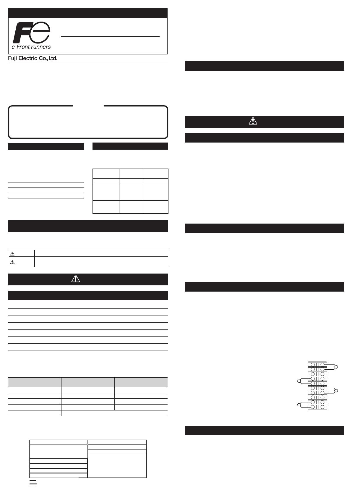
-When inductive loads such as magnetic opening/closing equipment, etc. as relay
output equipment are connected, use of "Z-trap," manufactured by Fuji Electric
Device Technology Co., Ltd., is recommended in order to protect the contacts against
opening/closing surges and to ensure long-term use.
Model names : ENE241D-07A (For 100V power
voltage)
: ENE471D-07A (For 200V power
voltage)
Attachment position : Please connect between the
relay control output contacts.
-To comply with CE marking (EMC), we recommend to
attach ferrite core to communication cable and power
cable.
-For wiring to the terminal block, apply crimp type
terminals size M3.
Screw size : M3 x 7 (with square washer)
Screw tightening torque : 0.78N-m (8kgf-cm)
2-4 Error Operation
-The alarm function does not work properly when an error occurs unless the settings
are made correctly. Always verify its setting before operation.
-In case of error input, PWR LED will ash. When replacing the sensor, make sure to
turn the power OFF.
- 1 -
INP-TN1PUMAa-E
11
12
13
14
15
16
17
18
19
20
21
22
23
24
25
26
27
28
29
30
Z-trap connecting diagram
LED indicator
Six LED lamps indicate the following operational conditions.
LED LED Status Color Operational condition
PWR
Illuminated green Normal operation
(Slave station of internal communication)
Blinking green Normal operation
(Master station of internal communication)
Illuminated red System fault
(A/D converter error, internal communication
error)
Blinking red Input error
COM Illuminated green RS-485 receiving
Illuminated orange RS-485 transmitting
OUT1 - 4 Illuminated green Corresponding channel outputting
Illuminated red Corresponding channel input error
-Actions to be displayed for COM and OUT1 -4 can be allocated by programming.
Setting
-Setting Station No.
Set Station No. of each controller before mounting.
Apply a ne tip at-head screwdriver to turn the Station No. conguration switch.
Rotary SW setting Station No.
0 1
1 2
2 3
34
45
5 6
6 7
7 8
8 9
9 10
A 11
B 12
C 13
D14
E 15
F 16
-Each of connected controllers must have a different Station No. from other
controllers. Duplicate Station No. may cause malfunction of the equipment.
LOADER
PUM-A
PWR
COM
OUT1
OUT2
OUT3
OUT4
STATION
4
3
2
1
0
F
E
D
C
B
A
9
8
7
6
5
Station No.
Configuration switch
Mounting
-Dimensions
LOADER
PUM-A
PWR
COM
OUT1
OUT2
OUT3
OUT4
STATION
1.5 6
30
85
(10)
(8)
(30)
100
5
50
6.1
Front screw terminal cover
(optional)
When locking tab is released
(when mounting /
dismounting to / from DIN rails)
Main unit
(when detached from the base part)
Terminal block
(when detached from the main unit)
DIN rail
Base part
(when detached from
the main unit)
[mm]
Terminal
Screw size M3
Terminal
Screw size M3
Cautions when mounting
In order to aid heat dissipation, 30mm of clearance (50mm recommended) above and
under the controllers should be provided.
30 or more30 or more
[mm]
-Mounting to DIN rails
1. Pull down the locking tab of the
base part. Hook the back of the
controller onto the upper part of
DIN rail.
2. Push the controller in the
direction of arrow 2.
3. Push up the locking tab to fasten
the controller onto DIN rail.
-When connecting controllers after
mounting to DIN rail, push up the
locking tab after doing so.
-Attaching end plates
When mounting controllers to DIN rails, we recommend to attach side connecting
terminal covers (right and left 1set), then end plates (optional) to the ends of the
rightmost and leftmost controllers.
LOADER
PUM-A
PWR
COM
OUT1
OUT2
OUT3
OUT4
STATION
4
3
2
1
0
F
E
D
C
B
A
9
8
7
6
5
LOADER
PUM-E
PWR
COM
STATION
4
3
2
1
0
F
E
D
C
B
A
9
8
7
6
5
Di1
Di2
Di3
Di4
Di5
Di6
Di7
Di8
Do1
Do2
Do3
Do4
Do5
Do6
Do7
Do8
LOADER
PUM-E
PWR
COM
STATION
4
3
2
1
0
F
E
D
C
B
A
9
8
7
6
5
Di1
Di2
Di3
Di4
Di5
Di6
Di7
Di8
Do1
Do2
Do3
Do4
Do5
Do6
Do7
Do8
LOADER
PUM-E
PWR
COM
STATION
4
3
2
1
0
F
E
D
C
B
A
9
8
7
6
5
Di1
Di2
Di3
Di4
Di5
Di6
Di7
Di8
Do1
Do2
Do3
Do4
Do5
Do6
Do7
Do8
LOADER
PUM-E
PWR
COM
STATION
4
3
2
1
0
F
E
D
C
B
A
9
8
7
6
5
Di1
Di2
Di3
Di4
Di5
Di6
Di7
Di8
Do1
Do2
Do3
Do4
Do5
Do6
Do7
Do8
Side connecting terminal cover
(right & left 1 set)
DIN rail mounting
end plate
DIN rail mounting
end plate
- 2 -
Hook the back
of controller
DIN rail
Locking tab
Part names and Functions
-Main unit
LOADER
PUM-A
PWR
COM
OUT1
OUT2
OUT3
OUT4
STATION
4
3
2
1
0
F
E
D
C
B
A
9
8
7
6
5
LED indicator
Loader communication port
Station No.
Configuration switch
See [Setting]
CT connector
See [Wiring]
Input/output
terminal block
See [Wiring]
-Base part
Mounting screw hole
Module connector
Mounting screw hole
See [Mounting]
Locking tab
RS-485 terminal block
See [Wiring]
Power terminal block
See [Wiring]
Module connector
(Connect controllers
laterally)
2-5 Others
-Please do not wipe the equipment with organic solvents such as alcohol or benzene,
etc. If wiping is necessary, use a neutral cleaning agent.
-Do not use mobile phones near this equipment (within 50cm). Otherwise a
malfunction may result.
-Malfunctions may occur if the equipment is used near a radio, TV, or wireless device.
-This equipment requires approx. 20 seconds before it starts to output.
-Before installing and wiring, take necessary measures for electrostatic discharge
(ESD).
- 3 -
-Fixing with screws
When mounting controllers inside a cabinet with screws, connect the base parts of
controllers rst.
-Fixing screws are not included. Please prepare screws as required.
1. Refer to the gure below for the mounting screw hole
size to decide the mounting position.
2. Remove the main unit from the base part.
See [How to detach the base part]
3. Connect base parts. Push up to fasten all the locking tabs.
4. Fixate the base parts onto the mounting position inside the cabinet with screws.
5. Attach the main unit to the base parts.
-Connecting controllers
1. Check that locking tabs are pulled down
(released).
2. Connect controllers with each other using
side connectors.
3. After mounting controllers onto DIN rail,
make sure to push up all locking tabs.
Controllers are fastened to DIN rail and to
each other.
4. All connected controllers are connected
to power supply and RS-485 via side
connectors if one of controllers is directly
connected to them.
Wiring
-Front terminal block (1ch type / 2ch)
LOADER
PUM-A
PWR
COM
OUT1
OUT2
OUT3
OUT4
STATION
4
3
2
1
0
F
E
D
C
B
A
9
8
7
6
5
11
12
13
14
15
16
17
18
19
20
21
22
23
24
25
26
27
28
29
30
Relay contact
output
11
12
SSR drive
output
11
12
11
12
13
14
13
15
14
13
15
16
17
16
17
16
17
18
19
20
*In case of currenet input, attach I/V unit which comes with the controller to the voltage input terminal.
19
18
20
19
18
20
CH1
CH2
14
15
Control output 1
Process value
input 1
Control output 2
Process value
input 2
Current
output
Relay contact
output
SSR drive
output
Current
output
Thermocouple
input
Resistance
bulb input
Voltage/Current
input*
Thermocouple
input Resistance
bulb input
Voltage/Current
input*
-Front terminal block (3ch, 4ch)
CH3
CH4
LOADER
PUM-A
PWR
COM
OUT1
OUT2
OUT3
OUT4
STATION
4
3
2
1
0
F
E
D
C
B
A
9
8
7
6
5
11
12
13
14
15
16
17
18
19
20
21
22
23
24
25
26
27
28
29
30
28
27
26
27
26
28
26
27
28
23
21
22 22
21
23
21
22
23
29
30
29
30
29
30
24
25
24
25
24
25
Relay contact
output
SSR drive
output
Control output 3 Process value
input 3
Control output 4 Process value
input 4
Current
output
Relay contact
output
SSR drive
output
Current
output
Thermocouple
input
Resistance
bulb input
Voltage/Current
input*
Thermocouple
input
Resistance
bulb input
Voltage/Current
input*
*In case of currenet input, attach I/V unit which comes with the controller to the voltage input terminal.
-Base part (power terminal, RS-485 terminal)
RS-485 terminal
A (+)
B (-)
SG
DC 24V (-)
Power terminal
DC 24V (+)
All connected controllers are connected to power supply and RS-485 via side connectors
if one of controllers is directly connected to them.
-CT input terminal
LOADER
PUM-A
PWR
COM
OUT1
OUT2
OUT3
OUT4
STATION
4
3
2
1
0
F
E
D
C
B
A
9
8
7
6
5
CN1 CN2
Terminal
layout Terminal
layout
*Pin No. 2,4, 6,8 of CN1 and CN2 are connected inside the equipment.
*CN2 cannot be used for PUMB.
LOADER
PUM-A
PWR
COM
OUT1
OUT2
OUT3
OUT4
STATION
4
3
2
1
0
F
E
D
C
B
A
9
8
7
6
5
LOADER
PUM-A
PWR
COM
OUT1
OUT2
OUT3
OUT4
STATION
4
3
2
1
0
F
E
D
C
B
A
9
8
7
6
5
Side
connector Locking tab
LOADER
PUM-A
PWR
COM
OUT1
OUT2
OUT3
OUT4
STATION
4
3
2
1
0
F
E
D
C
B
A
9
8
7
6
5
LOADER
PUM-A
PWR
COM
OUT1
OUT2
OUT3
OUT4
STATION
4
3
2
1
0
F
E
D
C
B
A
9
8
7
6
5
LOADER
PUM-A
PWR
COM
OUT1
OUT2
OUT3
OUT4
STATION
4
3
2
1
0
F
E
D
C
B
A
9
8
7
6
5
(30)
9
0.2
±
88.5
0.2
±
(100)
(3)
30
+0.7
+0.2
2-M3
[mm]
How to detach the base part
1. Press the lock lever on the top of the
main unit.
2. Pull down the upper part of main unit.
3. Detach the cutout on the lower end of
back of main unit from the projection
on the base part.
-When attaching the main unit to the
base part, take the reverse procedure
to removing the main unit from the
base part.
-Make sure that the lock lever of the
main unit is tted into the base part.
Lock lever
Main unit
Projection
- 4 -
Specication
General Specication
Power Supply : DC24V±10%
Power Consumption : Maximum 3.2W (135mA) [when DC24V is applied]
Dimensions : 30 (W)×100 (H)×85 (D) mm (excluding terminal cover and projection)
Weight : Approx.200g
Installation method : DIN rail mounting or mounting inside a cabinet with M3 screws
Ambient temperature* : -10 to 50 degrees C
* "Ambient temperature" is the temperature underneath the controller
inside the equipment or the cabinet where the controller is installed.
Ambient humidity : 90% RH or less (non condensing)
Process value input
No. of input : 2 or 4 points (1point/channel)
Input signal : Thermocouple K, J, T, E, R, B, S, N, PL-II
Resistance bulb Pt100, JPt100
DC voltage or DC current :
0 to 5Vdc, 0 to 10Vdc, 2 to 10Vdc,
0 to 20mAdc, 4 to 20mAdc
Input impedance : Thermocouple input, voltage input : 1M ohm or more
- Voltage input (V) : Approx. 1M ohm
- Current input : 250 ohm
Signal source resistance - Thermocouple : 0.3%FS ± 1 digit per 100 ohm
- Voltage input (V) : 0.3%FS ± 1 digit per 500 ohm
Allowable wiring resistance - Resistance bulb input : 10 ohm or less per wire
Heater break detector (CT) input
No. of input : 4 or 8 points (2 points/control channel)
Input type : Single-phase type CT/point 1 to 30A : CTL-6-S-H
20 to 50A : CTL-12-S36-8
Connection method : Special connector for Heater break detector (optional)
Control output
No. of output : 2 points (1 point/control channel) or 4 points (2 points/control channel)
Control output behavior : Heat (reverse action) or Cool (direct action)
or Heat/cool (control output 2points/control channel required)
Output type a) Relay contact output
- Proportion cycle : 1 to 150 sec.
- Contact structure : SPST contact
- Contact capacity :
220Vac / 30Vdc, 3A (resistance load)
220Vac / 30Vdc, 1A (inductive load)
- Minimum switching current : 100mA (24Vdc)
- Mechanical life : 20,000,000 switching
or more (100/min.)
- Electric life : 100,000 switching
or more (rated load)
b) SSR/SSC drive output
- Proportion cycle : 1 to 150 sec.
- Minimum resolution : 5ms
- ON Voltage : 10Vdc (8 to 12Vdc)
- OFF Voltage : 0.5Vdc or less
- Maximum Current : 20mAdc (per point)
- Load resistance : 500 ohm or more
c) Current output (4-20mAdc, 0-20mAdc)
- Actual output range : 0mA to 20.6mAdc
- Accuracy : ±0.3%FS (1mA or less : ±5%FS)
- Linearity : ±0.3%FS (1mA or less : ±5%FS)
- Resolution : 5000 or more
- Ripple current : P-P0.3mA or less
- Load resistance : 300 ohm or less
Analog re-transmission output
No. of output : 2 points (OUT3, OUT4 applied)
Output type : Current output (4-20mAdc, 0-20mAdc)
Communication functions
RS-485 interface
Communication standard : RS-485
Communication, synchro
method : Two-wire, half-duplex, asynchronous cycle
Communication speed : 9.6k, 19.2k, 38.4k, 115.2kbps
Data form : data bit ; 8, parity ; even/odd/none
Communication distance : 1km (38.4kbps or less), 250m (115.2kbps)
Connectable units : 33 units (both master and slave units included)
(32 units if any modules other than PUM series is included in slaves)
Protocol : Modbus RTU compatible
Loader (RS-232C) interface
Communication standard : RS-232C
Communication, synchro
method : Half-duplex, asynchronous cycle
Communication speed : 19.2kbps (xed)
Data form : data bit 8, no parity
Protocol : Modbus RTU compatible
Crimp terminal size
Please prepare power cables and crimp terminals of the size indicated below.
Power cable
Cable type Size
Thermocouple (Compensation lead wire) 1.25mm2 or less
Power supply 1.25mm2 or less
Crimp terminal
Cable size Screw tightening torque
0.25 to 1.25mm20.8Nm
Model code
Control module (4ch)
1 2 3 4 5 6 7 8 9 10 11 12 13
P U 1 0 0 0 Description
M
Module type
A 4ch control module
Input type
T Thermocouple / resistance bulb [all channels]
A
C
Voltage / current [all channels]
Thermocouple / resistance bulb [ch1,2],
voltage / current [ch3,4]
OUT1,2 output type
A Relay output
C SSR drive output
E Current output
OUT3,4 output type
A Relay output
C SSR drive output
E Current output
Operation Manual
A Japanese
B English
Option 1
Y Not fitted
C CT input (8 points)
Control module (2ch)
1 2 3 4 5 6 7 8 9 10 11 12 13
P U 1 0 0 0 Description
M
Module type
B 2ch control module
Input type
T Thermocouple / resistance bulb [all channels]
AVoltage / current [all channels]
OUT1,2 output type
A Relay output
C SSR drive output
E Current output
OUT3,4 output type
Y Not fitted
A Relay output
C SSR drive output
E Current output
Operation Manual
A Japanese
B English
Option 1
Y Not fitted
C CT input (4 points)
Accessories (optional)
12345678
P U M Z *Description
A 0 1 RS-485 terminating resistance
A 0 2 DIN rail mounting end plate
A 0 3 Side conneting terminal cover (right & left 1 set)
A 0 4 Front face screw terminal cover
L01 Loader connecting cable (RS-232C)
C 0 1 CT input terminal cable (for 4 points) [l=1m]
C 0 3 CT input terminal cable (for 4 points) [l=3m]
C 0 5 CT input terminal cable (for 4 points) [l=5m]
C T 1 CT for 1 to 30A (CTL-6-S-H)
C T 2 CT for 2 to 50A (CTL-12-S36-8)
3.2mm
Ring crimp terminal Y crimp terminal
3.2mm
6.0mm or less
6.0mm or less
Gate City Ohsaki, East Tower, 11-2, Osaki 1-chome,
Shinagawa-ku, Tokyo 141-0032, Japan
http://www.fujielectric.com
Phone: 81-3-5435-7280, 7281 Fax: 81-3-5435-7425
http://www.fujielectric.com/products/instruments/
International Sales Div
Sales Group
  • Page 1 1
  • Page 2 2
  • Page 3 3
  • Page 4 4

FE PUMB User manual

Category
Electrical relays
Type
User manual

FE PUMB is a multi-loop module type temperature controller that offers precise temperature control for various industrial applications. It features:

  • Easy installation and wiring with clear instructions and necessary accessories included.
  • Reliable operation with built-in protective circuits to prevent accidents and equipment damage.
  • Versatile input and output options for different sensor types and control requirements.
  • User-friendly interface with LED indicators for operational status and error notifications.

Ask a question and I''ll find the answer in the document

Finding information in a document is now easier with AI