Tripp Lite CS16AC Owner's manual

Category
Interface hubs
Type
Owner's manual
Table of Contents
1. Important Safety Instructions 2
2. Overview 2
3. Feature Identification 3
4. Enclosure Installation 4
4.1 Preparation 4
4.2 Unpacking 4
4.3 Ground Connection 4
5. Wall-Mounting the Enclosure 5
5.1 Mounting the 16-Port Models 5
5.2 Mounting the 32-Port and 5
48-Port Models
6. Enclosure Configuration 6
6.1 Door Locks 6
6.2 Cable Access and Management 6
7. 16-Port USB Charger/Hub 7
7.1 USB Charger/Hub Features 7
7.2 Connecting Devices to the 7
USB Charger/Hub
7.3 Connecting a Computer to the 7
USB Charger/Hub
8. Adjusting Storage Shelf Dividers 8
8.1 Adjusting the 16-Port Models’ 8
Shelf Dividers
8.2 Adjusting the 32-Port and 8
48-Port Models’ Shelf Dividers
9. Specifications 8
10. Optional Casters and Handle 9
11. Storage and Service 9
12. Warranty and Product Registration 9
Español 10
Français 19
Tablet Charge and Sync Station
16-Port Models: CS16USB, CS16USBW
32-Port Models: CS32USB, CS32USBW
48-Port Models: CS48USB, CS48USBW
Owner’s Manual
1111 W. 35th Street, Chicago, IL 60609 USA • www.tripplite.com/support
Copyright © 2015 Tripp Lite. All trademarks are the sole property of their respective owners.
PROTECT YOUR INVESTMENT!
Register your product for quicker service and ultimate peace of mind.
You could also win an ISOBAR6ULTRA surge protector—a $50 value!
www.tripplite.com/warranty
2
1. Important Safety Instructions
2. Overview
SAVE THESE INSTRUCTIONS
This Manual contains instructions and warnings that must be followed during the installation and operation of the product described in this manual.
Failure to comply may invalidate the warranty and cause property damage or personal injury.
USB Charger/Hub Unit:
To remove the USB Charger/Hub from the supply mains, the appliance inlet serves as a disconnect device.
If any of the following situations arise, schedule an appointment to have your equipment inspected by a service technician:
The equipment has been exposed to moisture
The equipment has been dropped and damaged
The equipment shows obvious signs of breakage
The equipment is not functioning properly or is not functioning according to the instructions described in this Owner’s Manual
Use of this equipment in life support applications where failure of this equipment can reasonably be expected to cause the failure of the life support
equipment or to significantly affect its safety or effectiveness is not recommended.
Do not use this equipment in the presence of a flammable anesthetic mixture with air, oxygen or nitrous oxide.
Enclosure Unit:
Keep the enclosure in a controlled indoor environment away from moisture, temperature extremes, flammable liquids and gasses, conductive
contaminants, dust and direct sunlight.
Leave adequate space at the front and rear of the enclosure for proper ventilation. Do not block, cover or insert objects into the external ventilation
openings of the enclosure.
The enclosure is extremely heavy. Use caution when handling the enclosure. Do not attempt to unpack, move or install it unassisted. Use a
mechanical device such as a forklift or pallet jack to move the enclosure in the shipping container.
Do not place any object on the enclosure, especially containers of liquid, and do not attempt to stack the enclosures.
Inspect the shipping container and the enclosure for shipping damage. Do not use the enclosure if it is damaged.
Leave the enclosure in the shipping container until it has been moved as close to the final installation location as possible.
For wall-mounted installations, first make sure that the wall surface can safely support the combined load of the enclosure, equipment and all
attached hardware and components.
For floor installations, make sure the unit is placed in a structurally sound area capable of bearing the weight of the enclosure, all equipment that
will be installed, and any other enclosures and/or equipment that will be installed nearby.
Enclosure must be installed by a qualified technician.
Use suitable mounting means when installing to cinder block, concrete, drywall or wood studs.
Use caution when cutting packing materials. The enclosure could be scratched, causing damage not covered by the warranty.
Save all packing materials for later use. Repacking and shipping the enclosure without the original packing materials may cause product damage
that will void the warranty.
If installing optional CSHANDLEKIT caster and handle kit—see section 10 for caster installation:
Do not push the enclosure from the side panels to move it. Pushing from the side panels will cause a tipping hazard.
When rolling the enclosure on its casters, always push it from behind; never pull it toward you.
A rolling enclosure can cause personal injury and property damage if not properly supervised. If rolling the enclosure down a ramp is required, use
extreme caution. Do not attempt to use ramps that have a slope grade greater than 12%.
Your tablet charging station is an all-in-one solution for storing, syncing and high-speed USB charging for up to 16, 32 or 48 tablets, including iPad
®
and Android™ models. Housed in a standard 19-inch rack enclosure, your tablet charging station can be conveniently mounted to walls, as well as
configured for desktop or floor placement (with optional rolling casters, sold separately). To prevent theft and device tampering, your tablet charging
station enclosure comes equipped with locking steel doors and side panels.
3
3. Feature Identification
CS16USB(W)
1
Locking Front Door
2
Horizontal Rails
3
Vertical Mounting Rails
4
Secure Top and Bottom Cable Access Plates
5
Vents
6
Locking/Removable Side Panels
7
Mounting Notches (found on the enclosure’s back panel)
8
Mounting Plate (separate piece)
9
Mounting Hooks (found on the Mounting Plate)
10
1U Rack-Mountable 16-Port USB Charger/Hub
11
Adjustable 16-tablet Storage Shelf
CS32USB(W)
1
Locking Rear Door
2
Locking/Reversible Front Door
3
Horizontal Rails
4
Vertical Mounting Rails
5
Secure Top and Bottom Cable Access Plates
6
Vents
7
Locking/Removable Side Panels
8
1U Rack-Mountable 16-Port USB Charger/Hub
9
Adjustable 16-tablet Storage Shelf
CS48USB(W)
1
Locking Rear Door
2
Locking/Reversible Front Door
3
Horizontal Rails
4
Vertical Mounting Rails
5
Secure Top and Bottom Cable Access Plates
6
Vents
7
Locking/Removable Side Panels
8
1U Rack-Mountable 16-Port USB Charger/Hub
9
Adjustable 16-tablet Storage Shelf
2
3
4
4
6
6
7
8
9
3
1
10
11
5
2
1
2
8
8
9
9
9
9
9
8
8
8
3
3
7
7
7
7
4
4
4
4
5
5
1
6
6
5
5
4
4. Enclosure Installation
Caution! Read All Instructions and Warnings Before Installation!
Warning: Rack enclosures can be extremely heavy. Do not attempt to unpack, move or install the enclosure without assistance.
Use extreme caution when handling the enclosure and be sure to follow all handling and installation instructions. Do not
attempt to install equipment without first stabilizing the enclosure.
4.1 Preparation
The enclosure must only be mounted to wall surfaces that can safely support the combined weight of the enclosure, equipment and all attached
hardware and components, or floor areas capable of handling the full enclosure load and contents as well as any other enclosures and/or equipment
that will be installed nearby. Before unpacking the enclosure, you should transport the shipping container close to the final installation location to
minimize the distance you will need to move the unit after the protective packaging has been removed. If you plan to store the enclosure for an
extended period before installation, follow the instructions in the Storage and Service section.
You need several tools:
• Level
Phillips-head screwdriver
Appropriate tools for wall mounting
You also need the following hardware:
Appropriate hardware for wall mounting (not included)
4.2 Unpacking
Use at least two people to unpack the enclosure.
Warning: Never attempt to lift or install without adequate help.
Do not try lifting the enclosure alone.
Note: The enclosure should be moved close to its installation location inside its shipping container before it is unpacked. For mobile applications, use the CSHANDLEKIT caster and
handle accessory kit.
1
Move shipping pallet to a firm, level surface.
2
Open box and remove the corner protectors. Upon unpacking, examine the inside of the cabinet for any additional packing material. Make sure to
remove all packing materials from the interior and exterior of the unit. Save all packing materials for later use unless you are certain they will not
be required. Packing materials are recyclable.
3
With one person on each side, carefully lift the enclosure out of the box and place on a firm, level surface.
4
Examine the enclosure for any damage or loose parts. Confirm all parts are present. If anything is missing or damaged, contact Tripp Lite for
assistance. Do not attempt to use the enclosure if it has been damaged.
4.3 Ground Connection
All parts of the enclosure are grounded to the
frame of the enclosure. Connect your facility’s
earth ground connection to the provided ground
stud
A
using an 8 AWG (3.264 mm) wire.
Warning: Attach each enclosure to earth
ground separately. Do not use the
enclosure without an earth ground
connection.
EARTH
GROUND
EARTH
GROUND
A
CS32USB(W)/CS48USB(W)CS16USB(W)
A
5
5. Wall-Mounting the Enclosure
Before mounting, use a level and tape measure to position your mounting area precisely. Be sure to
use appropriate fasteners (not included) to secure the enclosure to the wall. Warning: The area
you plan to mount the enclosure to must be able to withstand the weight of the
enclosure and all mounted equipment.
1
Using user-supplied hardware, attach the mounting plate to a wall or other suitable mounting
surface. Each mounting hole can accommodate an M8 or 5/16” bolt. The holes are spaced 16"
apart to accommodate standard stud placement as reflected in the diagram.
Note: When mounting the mounting plate to the wall, be sure the three mounting hooks are facing outwards and
away from the wall.
2
After the mounting plate has been securely attached to the mounting surface, hang the
enclosure’s three mounting notches onto the three mounting hooks on the plate attached to the
wall. The notches will fit over the hooks. The enclosure should slide down onto the hooks until
secure.
Note: Mounting notches exist on both the upper and lower rails of the back panel. This allows for mounting in the
standard or reversed positions.
3
After the mounting plate has been secured and the enclosure hung properly, secure the
enclosure to the mounting plate by installing the three supplied screws in the holes on the
mounting hooks as shown.
5.1 Mounting the 16-Port Models
5.2 Mounting the 32-Port and 48-Port Models
Warning: Do not attempt to mount the tablet charge and sync station to the wall with
any tablets or other personal electronic devices inside.
There are 16 keyhole cutouts on the back door of the enclosures. Each keyhole can accommodate
an M10 or 3/8” bolt (for the 32-port models) or an M5 or 3/16” bolt (for the 48-port models).
Each of the four keyhole sets are centered 16” apart horizontally and are spaced in 2.25”
increments toward the outer edges (see corresponding model diagrams for exact keyhole
measurements).
Using a level, measure to position your mounting areas precisely. Use appropriate fasteners (not
included) to secure the enclosure to the wall. Once the enclosure is safely hanging on the fasteners
and secured to the wall, open the unit from the rear door and tighten all mounting hardware.
Note: The tablet charge and sync station enclosure must be installed by a qualified technician. Before mounting, use a
level and tape measure to position your mounting area precisely. Use appropriate fasteners (not included) to secure the
tablet charge and sync station to the wall. Use suitable mounting means when installing to cinder block, concrete,
drywall or wood studs. Warning: The supporting surface must be able to safely support the combined load
of the equipment and all attached hardware and components. Go to the Specifications section on page 8
for more information on your model’s weight and dimensions.
16”
2.75”
2.75”
16”
A
A
B
B
C
C
1
2
3
17.858”
17.125”
19.375”
14.875”
16”
16”
16”
16”
12.625”
16”
28.4”
16”
28.4”
CS48USB(W)
CS32USB(W)
6
6. Enclosure Configuration
6.1 Door Locks
6.2 Cable Access and Management
The front and back doors have locks that are accessible using the included keys.
Note: Model CS16USB(W) does not contain a locking back door.
Each side panel locks using an L-shaped lever on the inside of the enclosure.
1
To unlock and remove the side panels, lift the shorter leg of the “L” up and pull it away from the
side panel. Pull the tab on the side panel and remove it from the enclosure.
2
To re-lock the side panels, secure it in the proper position, lift the shorter leg of the “L” up and
push it toward the side panel, back into the hole that it was in initially. Once it is in place, push
the shorter leg of the “L” down to lock it.
Note: To lock and unlock the side panels, you will need to have access to the interior of the enclosure.
To connect the tablet charge and sync station to a power outlet, run the power cord through the top
or bottom cable access plate containing a cord grommet by unlocking the front door and removing
one or both of the side panels (as shown in section 6.1)
1
. Then push the input plug through the
top or bottom cord grommet
2
and run the cord to your nearest 3-prong, grounded wall outlet
3
.
1
2
3
2
CS32USB(W)
7
Professional-grade USB charger/hub charges and syncs up to 16 USB devices, including iPads
®
, iPods
®
and iPhones
®,
as well as Android™ tablets
and smartphones.
Provides each USB port with an optimum charge level for a particular device (up to 2.4 amps).
Allows syncing to be performed with any device designed for USB data communications, per compatible file management software.
Syncs Apple
®
devices via iTunes
®
software or Apple Configurator.
Mini-USB Firmware Upgrade Port enables future software upgrades to support newer devices.
1U rack-mountable housing can be configured for professional, educational or personal installations.
IEC C14 inlet makes power connections easy, regardless of region or voltage requirement.
7.1 USB Charger/Hub Features
7. 16-Port USB Charger/Hub
A
2.4A USB Device Ports with LED Indicator Lights (16 total)
B
Computer Sync Port
C
Firmware Upgrade Port
D
Mounting Ears (Detachable)
Each storage shelf features 16 strain relief bushings that prevent the USB cable’s device
connectors from slipping through the bushing
A
. Using a user-supplied or device manufacturer’s
shielded USB cable, connect the USB cable to the device to be charged. Then pass the cable end
through the strain relief bushing on the storage shelf and connect the USB connector to a USB
charging port
B
. Repeat for all devices.
Tripp Lite offers individual and 10-pack cables for Apple
®
devices using USB to 30-Pin or USB to
Lightning™ cables, as well as individual and 10-pack cables for USB 3.0 or 2.0 devices using USB
A (male) to 5-Pin Micro B (male) cables.
Cable Type
Individual Cable
Model Number
10-Pack Cable
Model Number
Apple USB to 30-Pin Connector, 10” M110-10N-BK M110-10N-BK-10
Apple USB to 8-Pin Lightning Connector, 10" M100-10N-BK M100-10N-BK-10
USB 3.0 SuperSpeed A (Male) to 5-Pin Micro-B (Male), 1' U326-001-BK U326-001-BK-10
USB 2.0 Reversible A (Male) to 5-Pin Micro-B (Male), 1’ UR050-001* UR050-001-10*
* Features a reversible USB A (male) connector for simplified installations.
Visit www.tripplite.com for more information on our selection of premium USB cables.
7.2 Connecting Devices to the USB Charger/Hub
7.3 Connecting a Computer to the USB Charger/Hub
In addition to device charging, the USB Charger/Hub is equipped with a hub function that syncs devices and their respective software applications via a
connected computer. To enable the hub function, use the included USB cable to connect the USB B connector into the unit’s Computer Sync Port and
the USB A connector into a computer’s USB port.
Note: When a computer connection is established and multiple devices are connected to the USB Charger/Hub (Model: U280-016-RM), the charge rate will reduce during syncing and
resume to the normal charge rate upon completion.
Note: The Firmware Upgrade Port requires a mini-USB connection (cable not included).
A
BCD D
A
B
8
9. Specifications
8. Adjusting Storage Shelf Dividers
Your tablet charging station comes with one, two or three storage shelves with adjustable dividers
that can each accommodate up to 16 personal electronic devices per shelf.
8.1 Adjusting the 16-Port Models’ Shelf Dividers
Remove any personal electronic devices stored on the shelf tray. Then remove the shelf tray from
the cabinet by unscrewing the four fasteners attached to the two front rack rails. Once the shelf is
removed, rearrange the dividers by pulling them out or snapping them into the shelf tray.
8.2 Adjusting the 32-Port and 48-Port Models’ Shelf Dividers
Remove any personal electronic devices stored on the shelf tray. Then unlock and open the rear
door to the cabinet. From the front or rear of the cabinet, rearrange the dividers by pulling them out
or snapping them into the shelf tray. Repeat as necessary for additional shelf trays.
Model CS16USB/CS16USBW CS32USB/CS32USBW CS48USB/CS48USBW
Dimensions (H x W x D) 14.5 x 23.63 x 17.5”
(368 x 600 x 445 mm)
21.6 x 23.63 x 21.6”
(549 x 600 x 549 mm)
35.6 x 23.6 x 21.6”
(905 x 600 x 549 mm)
Unit Weight
29 lb. (13 kg) 55 lb. (25 kg)
96 lb. (43.5 kg)
Load Capacity* 200 lb. (90 kg)
Stationary or Rolling
200 lb. (90 kg)
Stationary or Rolling
250 lb. (113 kg)
Stationary or Rolling
Cabinet Mounting Depth
(Adjustable)
3” to 16.5” (76 to 419 mm) 3” to 20.5” (76 to 521 mm) 3" to 20.5" (76 to 521 mm)
Charger/Hub Ports 16 x USB 2.0 A (Female)
1 x USB 2.0 B (Female)
1 x USB 2.0 mini (Female)
32 x USB 2.0 A (Female)
2 x USB 2.0 B (Female)
2 x USB 2.0 mini (Female)
48 x USB 2.0 A (Female)
3 x USB 2.0 B (Female)
3 x USB 2.0 mini (Female)
Transmission Speed Up to 480 Mbps Up to 480 Mbps Up to 480 Mbps
Power Requirement Input: 100-240V, 2.5A, 50/60 Hz
Output: 5.0V, 2.4A Max (per USB
port)
Input: 100-240V, 2.5A, 50/60 Hz
Output: 5.0V, 2.4A Max (per USB
port)
Input: 100-240V, 2.5A, 50/60 Hz
Output: 5.0V, 2.4A Max (per USB
port)
Operating Temperature 32° to 104° F
0° to 40° C
32° to 104° F
0° to 40° C
32° to 104° F
0° to 40° C
Operating Humidity 5 to 95% RH, Non-Condensing 5 to 95% RH, Non-Condensing 5 to 95% RH, Non-Condensing
Number of Charger/Hub Units 1 2 3
Charger/Hub Dimensions per Unit
(H x W x D)
1.75 x 17.5 x 9.5”
(45 x 445 x 240 mm)
1.75 x 17.5 x 9.5”
(45 x 445 x 240 mm)
1.75 x 17.5 x 9.5”
(45 x 445 x 240 mm)
Enclosure Material Metal Metal Metal
Regulatory Approvals UL 60950, TUV (US and Canada),
NOM (Mexico) and RoHS
UL 60950, TUV (US and Canada),
NOM (Mexico) and RoHS
UL 60950, TUV (US and Canada),
NOM (Mexico) and RoHS
*Full wall-mount load capacity requires a mounting surface capable of bearing the full load of the tablet charge and sync station and all connected components. Rolling applications
require optional CSHANDLEKIT accessory kit. Specifications are subject to change without notice.
9
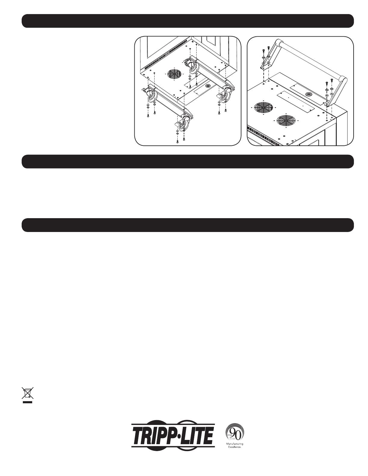
For applications requiring extra mobility, an
optional caster and handle accessory kit
(Model: CSHANDLEKIT) contains two swivel/
locking casters, two swivel-only casters and a
handle that attaches to the top of a charging
station unit. For further installation instructions,
refer to the manual included with the
CSHANDLEKIT.
2-Year Limited Warranty
Seller warrants this product, if used in accordance with all applicable instructions, to be free from original defects in material and workmanship for a period of 2 years from the date of initial purchase. If the product
should prove defective in material or workmanship within that period, Seller will repair or replace the product, at its sole discretion.
THIS WARRANTY DOES NOT APPLY TO NORMAL WEAR OR TO DAMAGE RESULTING FROM ACCIDENT, MISUSE, ABUSE OR NEGLECT. SELLER MAKES NO EXPRESS WARRANTIES OTHER THAN THE WARRANTY
EXPRESSLY SET FORTH HEREIN. EXCEPT TO THE EXTENT PROHIBITED BY APPLICABLE LAW, ALL IMPLIED WARRANTIES, INCLUDING ALL WARRANTIES OF MERCHANTABILITY OR FITNESS, ARE LIMITED IN DURATION
TO THE WARRANTY PERIOD SET FORTH ABOVE; AND THIS WARRANTY EXPRESSLY EXCLUDES ALL INCIDENTAL AND CONSEQUENTIAL DAMAGES. (Some states do not allow limitations on how long an implied
warranty lasts, and some states do not allow the exclusion or limitation of incidental or consequential damages, so the above limitations or exclusions may not apply to you. This warranty gives you specific legal
rights, and you may have other rights which vary from jurisdiction to jurisdiction).
WARNING: The individual user should take care to determine prior to use whether this device is suitable, adequate or safe for the use intended. Since individual applications are subject to great variation, the
manufacturer makes no representation or warranty as to the suitability or fitness of these devices for any specific application.
Product Registration
Visit www.tripplite.com/warranty today to register your new Tripp Lite product. You’ll be automatically entered into a drawing for a chance to win a FREE Tripp Lite product!*
* No purchase necessary. Void where prohibited. Some restrictions apply. See website for details.
Regulatory Compliance Identification Numbers
For the purpose of regulatory compliance certifications and identification, your Tripp Lite product has been assigned a unique series number. The series number can be found on the product nameplate label, along
with all required approval markings and information. When requesting compliance information for this product, always refer to the series number. The series number should not be confused with the marketing name
or model number of the product.
FCC Notice, Class B
This device complies with part 15 of the FCC Rules. Operation is subject to the following two conditions: (1) This device may not cause harmful interference, and (2) this device must accept any interference
received, including interference that may cause undesired operation.
Note: This equipment has been tested and found to comply with the limits for a Class B digital device, pursuant to part 15 of the FCC Rules. These limits are designed to provide reasonable protection against
harmful interference in a residential installation. This equipment generates, uses and can radiate radio frequency energy and, if not installed and used in accordance with the instructions, may cause harmful
interference to radio communications. However, there is no guarantee that interference will not occur in a particular installation. If this equipment does cause harmful interference to radio or television reception,
which can be determined by turning the equipment off and on, the user is encouraged to try to correct the interference by one or more of the following measures:
• Reorient or relocate the receiving antenna.
• Increase the separation between the equipment and receiver.
• Connect the equipment into an outlet on a circuit different from that to which the receiver is connected.
• Consult the dealer or an experienced radio/TV technician for help.
Any changes or modifications to this equipment not expressly approved by Tripp Lite could void the user’s authority to operate this equipment.
WEEE Compliance Information for Tripp Lite Customers and Recyclers (European Union)
Under the Waste Electrical and Electronic Equipment (WEEE) Directive and implementing regulations, when customers buy new electrical and electronic equipment from Tripp Lite they are entitled to:
• Send old equipment for recycling on a one-for-one, like-for-like basis (this varies depending on the country)
• Send the new equipment back for recycling when this ultimately becomes waste
Tripp Lite has a policy of continuous improvement. Specifications are subject to change without notice.
11. Storage and Service
10. Optional Caster and Handle Accessory
12. Warranty and Product Registration
Storage
The enclosure should be stored in a controlled indoor environment away from moisture, temperature extremes, flammable liquids and gasses,
conductive contaminants, dust and direct sunlight. Store the enclosure in its original shipping container if possible.
Service
The enclosure is covered by the limited warranty described in this manual. For more information, visit www.tripplite.com/support.
1111 W. 35th Street, Chicago, IL 60609 USA • www.tripplite.com/support
28
1111 W. 35th Street, Chicago, IL 60609 USA • www.tripplite.com/support
15-04-288 93-3448_RevA
  • Page 1 1
  • Page 2 2
  • Page 3 3
  • Page 4 4
  • Page 5 5
  • Page 6 6
  • Page 7 7
  • Page 8 8
  • Page 9 9
  • Page 10 10
  • Page 11 11
  • Page 12 12
  • Page 13 13
  • Page 14 14
  • Page 15 15
  • Page 16 16
  • Page 17 17
  • Page 18 18
  • Page 19 19
  • Page 20 20
  • Page 21 21
  • Page 22 22
  • Page 23 23
  • Page 24 24
  • Page 25 25
  • Page 26 26
  • Page 27 27
  • Page 28 28

Tripp Lite CS16AC Owner's manual

Category
Interface hubs
Type
Owner's manual

Ask a question and I''ll find the answer in the document

Finding information in a document is now easier with AI