Page is loading ...

Installation Instructions
8302472A
IMPORTANT:
Installer: Leave Installation
Instructions with the homeowner.
Homeowner: Keep Installation
Instructions for future reference.
Save Installation Instructions for local
electrical inspector’s use.
IMPORTANT:
Read and save these
instructions.
Part No. 8302472 Rev. A
IMPORTANT:
Installer: Leave Installation
Instructions with the homeowner.
Homeowner: Keep Installation
Instructions for future reference.
Save Installation Instructions for local
electrical inspector’s use.
Write down the model and serial
numbers before installing range.
Both numbers are on the model/serial
rating plate, located on the surface below
the control panel.
Model # _______________________________
Serial #________________________________
Questions regarding features,
operation, performance, parts or
service? Call 1-800-422-1230 or visit
our web site at www.kitchenaid.com.
IMPORTANT:
Read and save these
instructions.
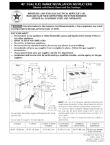
48" (121.9 cm) Commercial Style Dual Fuel Range
with self-cleaning thermal/convection oven
for residential use only
O
F
F
O
F
F
O
F
F
OF
F
O
F
F
OF
F
O
F
F
OF
F
O
F
F
OFF
O
F
F
O
F
F
O
F
F
OFF
O
FF
OFF
O
FF
OFF
O
F
F
O
F
F
O
F
F
OFF
O
F
F
O
F
F
backguard
(required for some installations)
For the way it’s made
®
®
WARNING
Tip Over Hazard
Achild or adult can tip the range and
be killed.
Connect anti-tip bracket to rear
range foot.
Reconnect the anti-tip bracket, if the
range is moved.
Failure to follow these instructions can
result in death or serious burns to
children and adults.

Before you start...
It is the customer’s responsibility:
• To contact a qualified electrical installer.
• To assure that electrical installation is
adequate and in conformance with
National Electrical Code, ANSI/NFPA
70 — latest edition**, or CSA Standard,
C22.1 Canadian Electrical Code, Part 1 —
latest edition*, and all local codes and
ordinances.
Cabinet opening dimensions shown must
be used. Given dimensions are minimum
clearances.
When installing a range under existing
cabinets and installation does not meet
the minimum cabinet clearances, install a
range hood above the range to avoid
burn hazards.
NOTE: Some cabinet and building
materials are not designed to withstand
the heat produced by the oven for baking
and self-cleaning. Check with your
builder or cabinet supplier to make sure
that the materials used will not discolor,
delaminate or sustain other damage.
All openings in the wall or floor where
the range is to be installed must be
sealed.
It is recommended that a range hood be
installed above this range.
IMPORTANT: Observe all governing
codes and ordinances.
NOTE: The range cooktop is
manufactured for use with Natural gas.
To convert to L.P./Propane gas, see the
Gas Conversion instructions provided in
literature package.
Proper gas and electrical supply
connections must be available. See “Gas
supply requirements,” Page 4 and
“Electrical requirements,” Page 5.
Do not obstruct flow of combustion and
ventilation air.
Proper installation is your responsibility.
Have a qualified technician install this
range. Make sure you have everything
necessary for correct installation. It is the
installer's responsibility to comply with
the installation clearances specified on
the gas information label. The gas
information label and model/serial rating
plate are located on the surface below
the control panel.
This installation must conform with all
local codes and ordinances. In the
absence of local codes, installation must
conform with American National
Standard, National Fuel Gas Code ANSI
Z223.1 — latest edition* or CAN/CGA —
B149 — latest edition* installation codes.
WARNING: If the
information in this manual
is not followed exactly, a
fire or explosion may result
causing property damage,
personal injury or death.
— Do not store or use
gasoline or other
flammable vapors and
liquids in the vicinity of
this or any other
appliance.
— WHAT TO DO IF YOU
SMELL GAS
• Do not try to light any
appliance.
• Do not touch any
electrical switch.
• Do not use any phone in
your building.
• Immediately call your
gas supplier from a
neighbor’s phone. Follow
the gas supplier’s
instructions.
• If you cannot reach your
gas supplier, call the fire
department.
— Installation and service
must be performed by a
qualified installer, service
agency or the gas
supplier.
2
Copies of the standards listed may be
obtained from:
*CSA International
8501 East Pleasant Valley Road
Cleveland, Ohio 44131-5575
** National Fire Protection Association
One Batterymarch Park
Quincy, Massachusetts 02269
WARNING
Your safety and the safety of
others are very important.
You can be killed or seriously injured
if you don't follow
instructions.
You can be killed or seriously injured
if you don't follow instructions.
We have provided many important safety
messages in this manual and on your
appliance.Always read and obey all
safety messages.
This is the safety alert symbol.
This symbol alerts you to
potential hazards that can kill
or hurt you and others.
All safety messages will follow the safety
alert symbol and either the word
“DANGER” or “WARNING.”These
words mean:
All safety messages will tell you what the
potential hazard is, tell you how to
reduce the chance of injury, and tell you
what can happen if the instructions are
not followed.
immediately
DANGER
In the State of Massachusetts, the
following installation instructions
apply:
• Installations and repairs must be
performed by a qualified or licensed
contractor, plumber, or gasfitter
qualified or licensed by the State of
Massachusetts.
• If using a ball valve, it shall be a
T-handle type.
• A flexible gas connector, when used,
must not exceed 3 feet.

Parts supplied for
installation
3
Product
dimensions
48" (121.9 cm)
cooktop width
48" (121.9 cm)
width
13-1/2"
(34.3 cm)
anti-tip
brackets
1-3/4"
(4.4 cm)
1"
(2.5 cm)
2 - #10 x 2"
phillips head screws
36" (91.4 cm)
cooktop
height with
feet
loosened
3/4 turns
NOTE:
regulator
located at
center bottom
of range.
48" (121.9 cm) range
with all sealed burners
shown
49-1/2"
(125.7 cm)
overall height
13" (33 cm) max.
upper cabinet depth
1/4" (6.4 mm)
spacer
26-1/2" (67.3 cm)
width with
control panel
• Anti-tip bracket must be securely
attached to a wall stud. Thickness of
finished wall may require using
longer screws to anchor the
bracket.
• L.P. conversion kit is included in
literature package.
• Backguard and island trim. The
backguard included with the range
must be installed when a standard
24” (61 cm) deep base cabinet is
used and there is zero clearance
between the back edge of range
and combustible rear wall.
For island installations or other
installations with more than 7"
(17.8 cm) clearance to back wall, use
the optional stainless steel island
trim, included with the range, to
cover the backguard mounting
flanges.
48" (121.9 cm) min.
upper cabinet width
48-1/4" (122.6 cm)
opening width
20"
(50.8 cm)
12"
(30.5 cm)
5-1/2" (14 cm)
8"
(20.3 cm)
18" (45.7 cm)
upper cabinet
to countertop
gas line opening to be
located in this area
junction box to be
located in this area
12" (30.5 cm) min.
clearance from both
sides of range to side
wall or other
combustible material
above cooking surface
0" (0 cm) clearance from
both sides and back of
range to adjacent
combustible construction
below cooking surface
*NOTE: 49" (124.5 cm) min. when bottom of wood
or metal cabinet is protected by not less than 1/4"
(6.4 mm) flame retardant millboard covered with
not less than No. 28 MSG sheet steel, 0.015"
(0.4 mm) stainless steel, 0.024" (0.6 mm)
aluminum or 0.020" (0.5 mm) copper.
55" (139.7 cm) min. clearance between the top of
the cooking platform and the bottom of an
unprotected wood or metal cabinet.
For minimum
clearance to top of
range, see NOTE.*
40"
(101.6 cm)
4"
(10.2 cm)
3" (7.6 cm) maximum
gas line height
3-1/2" (8.9 cm)
maximum junction
box height
Cabinet opening dimensions

4
Gas supply requirements
Observe all governing codes and
ordinances.
IMPORTANT: Range cooktop must be
connected to a regulated gas supply.
A.This installation must conform with
local codes and ordinances. In the
absence of local codes, installations must
conform with American National
Standard, National Fuel Gas Code
ANSI Z223.1 — latest edition* or
CAN/CGA-B149 — latest edition*
installation codes.
B.Input ratings shown on the
model/serial rating plate are for
elevations up to 2,000 feet (610 m). For
elevations above 2,000 feet (610 m),
ratings are reduced at a rate of 4% for
each 1,000 feet (305 m) above sea level.
(Not applicable for Canada.)
Copies of the standards listed may be
obtained from:
*CSA International
8501 East Pleasant Valley Road
Cleveland, Ohio 44131-5575
D.Provide a gas supply line of 3/4"
(1.9 cm) rigid pipe to the range location.
A smaller size pipe on long runs may
result in insufficient gas supply. Pipe-
joint compounds, appropriate for use
with L.P. gas, must be used. With L.P. gas,
piping or tubing size can be 1/2" (1.3 cm)
minimum. L.P. gas suppliers usually
determine the size and materials used on
the system.
L.P. Gas:
No attempt shall be made to convert the
cooktop from the gas specified on the
model/serial rating plate for use with a
different gas without consulting the
serving gas supplier. Conversion must be
done by a qualified service technician. To
convert to L.P. gas, use L.P. gas
conversion kit part no. 8301282. The parts
for this kit are in the literature package
supplied with range.
E. If local codes permit, a new AGA or
CSA design-certified, 4-5 foot (122-152.4
cm) long, 5/8" (1.6 cm) I.D., flexible metal
appliance connector is recommended for
connecting this range to the gas supply
line. Do not kink or damage the flexible
tubing when moving the range. A 1/2"
(1.3 cm) male pipe thread is needed for
connection to pressure regulator female
pipe threads.
F. The supply line must be equipped
with an approved manual gas shutoff
valve. This valve should be located in the
same room, but external to the range,
and should be in a location that allows
ease of opening and closing. Do not
block access to the shutoff valve.
to range
shutoff valve
“open” position
G.If rigid pipe
is used as a gas
supply line, a combination of pipe
fittings must be used to obtain an in-
line connection to the range. All strains
must be removed from the supply and
fuel lines so range will be level and in
line.
gas supply line
H.The regulator must be checked at a
minimum 1-inch (25.4 mm) water column
above the set pressure. The inlet pressure
to the regulator should be as follows for
operation and checking the regulator
setting:
NATURAL GAS:
Manifold pressure –
5 inches (12.7 cm) W.C.
Maximum pressure –
14 inches (35.6 cm) W.C.
L.P. GAS:
Manifold pressure –
10 inches (25.4 cm) W.C.
Maximum pressure –
14 inches (35.6 cm) W.C.
I.Line pressure testing:
Testing above 1/2 psi (3.5 kPa) (gauge):
The range and its individual manual gas
shutoff valve must be disconnected from
the gas supply piping system during any
pressure testing of that system at test
pressures greater than 1/2 psig (3.5 kPa).
Testing at 1/2 psi (3.5 kPa) (gauge)
or lower:
The range must be isolated from the gas
supply piping system by closing its
individual manual shutoff valve during
any pressure testing of the gas supply
piping system at test pressures equal to
or less than 1/2 psig (3.5 kPa).
C.The range is equipped for use with
Natural gas. It is design-certified by
International Approval Services (I.A.S.)
for Natural and L.P. gases with
appropriate conversion. The model/serial
rating plate, located on the surface below
the control panel, has information on the
type of gas that can be used. If this
information does not agree with the type
of gas available, check with the local gas
supplier.
WARNING
Explosion Hazard
Use a new AGA or CSA approved gas
supply line.
Install a shutoff valve.
Securely tighten all gas connections.
If connected to LP, have a qualified
person make sure gas pressure does
not exceed 14" (35.6 cm) water column.
Examples of a qualified person
include:
licensed heating personnel,
authorized gas company
personnel, and
Failure to do so can result in death,
explosion, or fire.
authorized service personnel.

4.Carefully move range close to the
cabinet opening. Place the rack in oven.
Place level on rack, first side to side; then
front to back.
If the range is not level, adjust the feet
up or down. Turn leveling leg sleeves to
level range and to raise or lower range to
the desired countertop height.
5
remove
screws
bottom
vent
leveling leg
sleeves
Electrical requirements
F. Connection at connection block must
be copper wire only.
If the house has aluminum wiring, follow
the procedure below:
a) Connect the aluminum wiring to the
copper wiring using special connectors
designed and Underwriters
Laboratories-listed for joining copper
to aluminum. Follow the electrical
connector manufacturer’s
recommended procedure.
b) Aluminum/copper connection must
conform with local codes and industry-
accepted wiring practices.
Copies of the standards listed may be
obtained from:
* National Fire Protection Association
One Batterymarch Park
Quincy, Massachusetts 02269
** CSA International
8501 East Pleasant Valley Road
Cleveland, Ohio 44131-5575
If codes permit and a separate ground
wire is used, it is recommended that a
qualified electrician determine that the
ground path and wire gauge are in
accordance with local codes.
Do not ground to a gas pipe.
Check with a qualified electrician if you
are not sure the range is properly
grounded.
Do not have a fuse in the neutral or
ground circuit.
This range must be connected to a
grounded metal, permanent wiring
system.
A.A four-wire or three-wire, single
phase, 240-volt, 60-Hz, AC-only electrical
supply is required on a separate,
50 amp circuit, fused on both sides of the
line. A time-delay fuse or circuit breaker
is recommended. The fuse size must not
exceed the circuit rating of the range
specified on the model/serial rating plate
located on the horizontal surface below
the control panel.
B.Wire sizes and connections must
conform to the requirements of the
National Electrical Code ANSI/NFPA 70 –
latest edition*, or CSA Standards C22.1-
94, Canadian Electrical Code, Part 1 and
C22.2 No. 0-M91 - latest edition** and all
local codes and ordinances.
C.The range should be connected
directly to the fused disconnect or circuit
breaker box through flexible, armored or
non-metallic sheathed, copper cable. The
flexible, armored cable extending from
the fuse box or circuit breaker box
should be connected directly to the
junction box.
D.Locate the junction box to allow as
much slack as possible between the
junction box and the range so that the
range can be moved if servicing is ever
necessary. Do not cut the conduit.
E.A U.L.- or CSA-listed conduit
connector must be provided at each end
of the power supply cable (at the range
and at the junction box).
Installation
1.Remove shipping materials, tape
and protective film from range. Keep
shipping pallet under range. Unpack the
burner grates, burner caps, simmer plate,
grille grate, drip tray, spill guard, wave
tray, wave plate, tile bezels, regulator,
backguard and island trim. Items are
either packaged in the range or on the
range. Parts shipped with range depend
on model ordered.
2.Remove the two side trim pieces by
removing the 4 screws (2 per side).
Remove the bottom vent by removing
the 4 screws (2 on the top and 2 on the
side of the bottom vent). Slide the vent
down and pull toward you. Carefully lay
the parts to the side to avoid scratching
the stainless steel.
3.Lay a piece of cardboard from side
packing on the floor behind range. Using
2 or more people, firmly grasp each side
of range. Lift range up about 3 inches (8
cm) and move it back until the range is
off shipping pallet. Set range on
cardboard to avoid damaging floor.
5.Choose the correct bracket for your
installation.
• If the wall behind the range has no
baseboard or a baseboard up to 3/8"
(9.5 mm) thick, use the shorter 1"
(2.5 cm) anti-tip bracket.
• If the wall behind the range has a
baseboard thicker than 3/8" (9.5 mm),
use the longer 1-3/4" (4.4 cm) anti-tip
bracket.
Locate a stud in wall behind range.
Measure distance from top of rear brace
to floor. Add 5/16" (7.9 mm) to
measurement to allow anti-tip bracket to
slide over rear brace. Use this final
measurement and mark a horizontal line
on wall where stud is located.
write down
this distance
rear
brace
WARNING
ExcessiveWeight Hazard
Use two or more people to move and
install range.
Failure to do so can result in back or
other injury.

6
6.Position top of anti-tip bracket at
line marked in step 5 and mark holes.
Drill two 1/8" (3 mm) holes. Use screws
provided to fasten anti-tip bracket to wall.
NOTE: Anti-tip bracket must be mounted
securely to stud in wall behind the range.
Depending on thickness of the wall
covering, longer screws may be required.
7.Make electrical connection.
If your house has aluminum wiring, see
“Electrical requirements” page 5.
wall stud
line
mounting
screws
anti-tip
bracket
This range must be connected to a
grounded, metallic permanent wiring
system or a ground connector should be
connected to the ground terminal or wire
lead on the range.
This range is manufactured with a frame-
connected, bare or green ground wire.
Connect the range cable to the junction
box through the U.L.- or CSA-listed
conduit connector. Complete electrical
connection according to local codes and
ordinances.
7A.Where local codes do not permit
connecting the frame-ground conductor
to the neutral (white) junction box wire
(also used for Canadian installations):
1. Disconnect power.
2. Connect the flexible, armored cable
from the range to the junction box
using a U.L.- or CSA-listed conduit
connector. Tighten screws on conduit
connector.
junction box
4-wire cable from power supply
twist-on
connector
black wires
U.L.- or CSA- listed
conduit connector
4-wire cable from range
bare or green
wires
white wires
red wires
Figure 1
Ungrounded neutral
7B.Where local codes permit
connecting the frame-ground conductor
to the neutral (white) junction box wire
(not used for Canadian installations):
Figure 2
Grounded neutral
junction
box
red
wires
white
wire
white and bare
or green wires
3-wire cable from
power supply
black
wires
4-wire cable from range
U.L.- or CSA-
listed conduit
connector
1. Disconnect power.
2. Connect the flexible, armored cable
from the range to the junction box
using a U.L.- or CSA-listed conduit
connector. Tighten screws on conduit
connector.
3. Connect the two black wires together;
the two red wires together; and the
bare or green and white cooktop cable
wires to the white (neutral) wire in the
junction box using twist-on
connectors. (See Figure 2.)
3. Connect the two black wires
together; and the two red wires
together using twist-on connectors.
(See Figure 1.)
4. Connect the two white wires
together using twist-on connector.
5. Connect the bare or green ground
wire from the range cable to the
grounded wire in the junction box or
other grounded connector using
twist-on connector. (See Figure 1.)
Do not connect bare ground wire to
neutral (white) wire in junction box.
WARNING
Tip Over Hazard
Achild or adult can tip the range and
be killed.
Connect anti-tip bracket to rear
range foot.
Reconnect the anti-tip bracket, if the
range is moved.
Failure to follow these instructions can
result in death or serious burns to
children and adults.
Electrical Shock Hazard
Disconnect power before servicing.
Use 8 gauge copper wire.
Electrically ground range.
Failure to follow these instructions can
result in death, fire, or electrical shock.
WARNING

8.Using 2 or more people, remove
cardboard or hardboard from under range.
7
9.Attach the backguard or island trim
as required for your installation.
Attachment screws are in the literature
package.
10.Slide range completely back so
anti-tip bracket is over rear brace of
range.
11.Make gas connection. Assemble
flexible connector from gas supply pipe
to pressure regulator located in the
middle front of the range. Apply pipe-
joint compound made for use with L.P.
gas to the smaller thread ends of the
flexible connector adapters. Attach one
adapter to the pressure regulator elbow
and the other adapter to the gas shutoff
valve. Tighten both adapters.
13.Leak testing of the appliance
shall be conducted according to the
following instructions:
Test all connections using an approved
non-corrosive leak-detection solution.
Bubbles will show a leak. Correct any
leak found.
14.Put a burner cap on each burner
base. Place burner grates over burner
bases and caps.
15.Reconnect power. “PF” should
appear in the clock displays. (Refer to
your Use and Care Guide for instructions
on using the electronic control.)
12.Open manual shutoff valve in
gas supply line. Wait a few minutes for
gas to move through the line.
attaching the
backguard
attaching the
island trim
center hole
not used
3 front screws
(4 rear screws required
but not shown)
use pipe-joint
compound
flexible
connector
1/2" flare
union adapter
manual gas
shutoff valve
1/2" to 3/4"
gas pipe
a 1/2" male pipe thread is needed for connection
to pressure regulator female pipe threads
regulator
burner cap
burner
base
ignitor
electrode
gas tube
opening
to range
shutoff valve
“open” position
gas supply line

8
16A.Push in and turn the surface
burner knobs to the “LITE” position. The
surface burner flame should light within
4 seconds.
After lighting the burners, turn the
control knobs to "OFF".
If burners do not light properly, turn
control knob to the “OFF” position. Check
that burner cap is in the proper position.
Check that circuit breaker has not tripped
or house fuse has not blown. Check that
the manual gas shutoff valve is in the
“ON” position. Check operation again.
If a surface burner does not light at this
point, contact your KitchenAid dealer for
assistance.
cooktop
burners
valve
stem
16C. Check flame on “HI” for a
blue color. It should be clean and soft in
character. No yellow tip, blowing or
lifting of flame should occur. Occasional
orange flashes are normal and reflect
different elements in the air or gas.
16B.Adjusting the surface burner
or grille flame:
NOTE: there is no adjustment for the
griddle flame. Gas flow is at 100%,
temperature is controlled by thermostat.
Push in and turn each control knob to the
“LO” position. The “LO” setting of each
burner has been factory set to the lowest
position available to provide reliable
reignition of the burner. If it does not
stay lit on the “LO” position, check “LO”
position as follows:
a. Turn control knob to “LITE” until
burner ignites.
b. Quickly turn control knob down to
“LO” position.
c. If burner goes out, readjust valve as
follows:
Remove control knob. Insert a flat-blade
screwdriver into the hollow valve stem
and engage the slotted screw. Flame size
can be increased or decreased by turning
the screw. Adjust flame until you can
quickly turn control knob from “HI” to
“LO” position without extinguishing the
flame. Flame should be as small as
possible without going out.
ports
typical surface
burner flame at
highest setting
16.
Electronic Ignition System —
initial lighting
Surface burners use electronic ignitors in
place of standing pilots. When the
cooktop control knob is pushed in and
turned to the “LITE” position, the system
creates a spark to light the burner. This
sparking continues until the control knob
is turned to the desired setting.
Check the operation of the
surface burners.
17.Check operation of oven element.
Turn oven selector to “BAKE”. “350F” will
show on display. Press “Enter”. First
Preheat light comes on when oven
temperature begins to rise. When second
Preheat light comes on, open oven door
and hold hand above oven floor and feel
for heat. Do not touch oven floor. Press
“Cancel” and turn oven selector to
“Reset”.
18.Check the operation of the broiler
element. Turn oven selector to “BROIL”.
“HI” will show on display. Press “Enter”.
Look through oven window. The top
element should glow red and heat should
be radiating out of the door. Press
“Cancel” and turn oven selector to
“Reset”.
If the oven does not operate, check that
power supply is turned on, that no fuses
are blown, or no circuit breakers are
tripped. If the oven still does not operate,
contact your KitchenAid dealer or
designated service company.
19.Reinstall the bottom vent
pushing it upward until the holes line up
at top of vent. Reattach the vent using
the 4 screws removed in step 2. Reinstall
the 2 side trim pieces using the 4 screws
(2 each side) removed in step 2.
20.Place burner grates over burner
caps. The simmer plate may set on one
of the grates or be stored for future use.
(See Use and Care Guide.)
To get the most efficient use from your
new dual fuel range, read your
KitchenAid Use and Care Guide. Keep
Installation Instructions and Guide close
to the range for easy reference.

9
If range does not operate
Check that the circuit breaker is not
tripped or the house fuse blown.
Check that gas valves are turned to
the “ON” position.
See Use and Care Guide for
troubleshooting list.
✓
✓
✓
Installer checkoff list
Range correctly positioned in
countertop cutout.
Maintained specified distances to
cabinet surfaces.
Range level – front to back – side to
side.
Burner caps positioned properly on
sealed burner bases.
All packing material removed.
Backguard or island trim attached
(see page 3).
Depending on model, grille parts
correctly assembled.
Depending on model, griddle parts
correctly assembled.
✓
✓
✓
✓
✓
✓
✓
✓
If you need assistance
The KitchenAid Customer Interaction
Center will answer any questions about
operating or maintaining your range not
covered in the Installation Instructions.
The KitchenAid Customer Interaction
Center is open 24 hours a day, 7 days a
week. Just dial 1-800-422-1230 — the call
is free within the continental United
States, or visit our web site at
www.kitchenaid.com.
When you call, you will need the range
model number and serial number. Both
numbers can be found on the
model/serial rating plate located on the
surface below the control panel.
If you need service
In the event that your KitchenAid
appliance should need service, call the
dealer from whom you purchased the
appliance or a KitchenAid-designated
service company. A KitchenAid-
designated service company is listed in
the Yellow Pages of your telephone
directory under “Appliances —
Household — Major — Service and
Repair.”
You can also obtain the service
company's name and number by dialing,
free within the continental United States,
the KitchenAid Customer Interaction
Center telephone number, 1-800-422-
1230. A special operator will tell you the
name of your nearest KitchenAid-
designated service company.
Maintain the quality built into your
KitchenAid appliance — call a
KitchenAid-designated service company.
Maintenance
If removing the range is necessary for
maintenance, shut off gas supply.
Disconnect the gas and electric supply.
Finish removing the range.
RANGE
The range is connected only to type
of gas for which it is certified for
use.
✓
GAS SUPPLY

L2
N
L1
R
W
W
W
N
L1
M
TEMP SENSOR
1080
AT 70
°
F (21
°
C)
1654
AT 350
°
F (177
°
C)
~
CONV. FAN
BROIL-3000W
BAKE-2000W
CONV.-1600W
HALOGEN
5W/BULB
LATCH SWITCH
(OPERATED BY MOTOR)
DOOR SWITCH 1
BRN
BU
V
GRN
W
OR
BU
R
Y
R
GY
BK
BK
W
BK
W
t
°
BK
P4-1
P4-2
P7-4
P7-2
P7-3
P3-1
P1-3
P5-4
P5-1
P5-3
P1-1
P1-5
TAN
P7-1
W
W
TAN
TAN
W
R
~
M
BLOWER
DOOR LOCK
MOTOR LATCH
R
V
P7-5
ELECTRONIC CONTROL
LEFT SLAVE
DOUBLE LINE
BREAK RELAY
TOD
NON
RESETTABLE
P9-1
P9-3
(SEE *)
LATCH ASSY
Y
ORG
W
BK
BK
BK
OFF
AUTO
LIGHT
SWITCH
LIGHT POWER SUPPLY
ORG
W
W
W
R
CONTROL POWER
TRANSFORMER
BU
BU
P3-2
P3-3
CONTROL PANEL
THERMAL FUSE -
183
°
F (84
°
C) -
BU
W
W
BK
BU
W
BK
P3-2
P3-3
P9-1
P9-3
Y
ORG
LS2 LS1
M
~
W
BK
Y
Y
ORG
P8-1
P8-3
P8-2
P8-4
W
W
BK
BK
BK
BK
BK
W2
W1
LS4
LS3
WISP CONNECTOR
(MANUFACTURING
USE ONLY)
M
TEMP SENSOR
1080
AT 70
°
F (21
°
C)
1654
AT 350
°
F (177
°
C)
~
CONV. FAN
BROIL-3000W
BAKE-2000W
CONV.-1600W
LATCH SWITCH
(OPERATED BY MOTOR)
DOOR SWITCH 1
BRN
BU
V
GRN
W
OR
BU
R
Y
R
GY
BK
BK
W
BK
W
t
°
BK
P4-1
P4-2
P7-4
P7-2
P7-3
P3-1
P1-3
P5-4
P5-1
P5-3
P1-1
P1-5
TAN
P7-1
W
W
TAN
TAN
R
~
M
BLOWER
DOOR LOCK
MOTOR LATCH
R
V
P7-5
SUPPRESSOR
WP#4451985
ELECTRONIC CONTROL
RIGHT SLAVE
DOUBLE LINE
BREAK RELAY
TOD
NON
RESETTABLE
P9-1
P9-3
(SEE *)
LATCH ASSY
Y
ORG
RS2
RS1
BK
BK
OFF
AUTO
LIGHT
SWITCH
LIGHT POWER SUPPLY
ORG
W
W
W
R
CONTROL POWER
TRANSFORMER
BU
BU
P3-2
P3-3
CONTROL PANEL
THERMAL FUSE -
183
°
F (84
°
C) -
BU
W
W
BK
BK
BU
M
~
W
BK
Y
Y
ORG
P8-1
P8-3
P8-2
P8-4
W
W
BK
W
BK
(*). BLOWER REMAINS OFF UNTIL OVEN REACHES
190
°
F (88
°
C) AND MAY CONTINUE RUNNING UP
TO 45 MINUTES AFTER OVEN HAS TURNED OFF
ELECTRONIC CONTROL
MASTER
HALOGEN
5W/BULB
W
W
BK
BK
BK
BK
BK
Y
ORG
L2
N
VALV E SWITCHES
IGNITOR
ELECTRODES
SPARK
MODULE 2
BRN OR YEL
W
W
W/BLU
GRNR
GND
R
W
R
IGNITOR
ELECTRODES
SPARK
MODULE 1
BRN OR YEL
W/BLU
GRNR
GND
W/BLU
Cooktop schematic
Oven schematic
Part No. 8302472 Rev. A
© 2004 KitchenAid
® Registered Trademark/Trademark of
KitchenAid U.S.A., KitchenAid
Canada licensee in Canada
Prepared by KitchenAid, Benton Harbor, Michigan 49022
Printed in U.S.A.
03/2004
®

L2
NEU.
L1
R
BL
BL
BL
NEU.
L1
M
CAPTEUR DE TEMPÉRATURE
1080
À 21˚
C
(70
˚F
)
1654
À
177˚C (350˚F)
CAPTEUR DE TEMPÉRATURE
1080
À 21˚
C
(70
˚F
)
1654
À
177˚C (350˚F)
~
MOTEUR DU VENTILATEUR
CONVECTION
GRIL-3000W
FOUR-2000W
CONVECTON-1600W
MAR
BU
VI
VERT
BL
OR
BU
R
JA
R
GY
N
N
BL
N
BL
t˚
N
P4-1
P4-2
P7-4
P7-2
P7-3
P3-1
P1-3
P5-4
P5-1
P5-3
P1-1
P1-5
TAN
P7-1
BL
BL
BL
TAN
TAN
BL
R
~
M
VENTILATEUR
MOTEUR DE VERROUILLAGE
DE LA PORTE
MOTEUR DE VERROUILLAGE
DE LA PORTE
R
VI
P7-5
MODULE DE COMMANDE
ÉLECTRONIQUE
CÔTÉ GAUCHE - ASSERVI
P9-1
P9-3
(*)
JA
OR
BL
N
N
N
OFF
AUTO
INTERRUPTEUR -
ÉCLAIRAGE
INTERRUPTEUR -
ÉCLAIRAGE
OR
BL
BL
BL
R
TRANSFORMATEUR -
ALIMENTATION CIRCUITS
DE COMMANDE
BU
BU
P3-2
P3-3
BU
BL
BL
N
BU
BL
N
P3-2
P3-3
P9-1
P9-3
JA
OR
LS2 LS1
M
~
N
JA
JA
OR
P8-1
P8-3
P8-2
P8-4
BL
N
N
NBL
BL
N
N
W2
W1
LS4
LS3
CONNECTEUR WISP
(UTILISÉ EN
FABRICATION
SEULEMENT)
M
~
MOTEUR DU VENTILATEUR
CONVECTION
GRIL-3000W
FOUR-2000W
CONVECTION.-1600W
CONTACTEUR DE VERROUILLAGE
(MANŒUVRE PAR LE MOTEUR)
CONTACTEUR DE VERROUILLAGE
(MANŒUVRE PAR LE MOTEUR)
CONTACTEUR DE PORTE 1
CONTACTEUR DE PORTE 1
MAR
BU
VI
VERT
BL
OR
BU
R
JA
R
GY
N
N
BL
N
BL
t˚
N
P4-1
P4-2
P7-4
P7-2
P7-3
P3-1
P1-3
P5-4
P5-1
P5-3
P1-1
P1-5
TAN
P7-1
BL
BL
TAN
TAN
R
~
M
VENTILATEUR
R
VI
P7-5
SUPPRESSEUR
WP#4451985
MODULE DE COMMANDE
ÉLECTRONIQUE
CÔTÉ DROIT - ASSERVI
RELAIS DISJONCTION
BIPOLAIRE
RELAIS DISJONCTION
BIPOLAIRE
TOD NON
RÉARMABLE
TOD NON
RÉARMABLE
P9-1
P9-3
(*)
SYSTÈME DE
VERROUILLAGE
SYSTÈME DE
VERROUILLAGE
JA
OR
RS2
RS1
N
N
OFF
AUTO
ALIMENTATION
ÉCLAIRAGE
ALIMENTATION
ÉCLAIRAGE
OR
BL
BL
BL
R
TRANSFORMATEUR -
ALIMENTATION CIRCUITS
DE COMMANDE
BU
BU
P3-2
P3-3
FUSIBLE THERMIQUE -
TABLEAU DE COMMANDE
84˚C (183˚F)
FUSIBLE THERMIQUE -
TABLEAU DE COMMANDE
84˚C (183˚F)
BU
BL
W
N
BK
BU
M
~
N
JA
JA
OR
P8-1
P8-3
P8-2
P8-4
BL
BL
BL
N
N
(*). LE VENTILATEUR RESTE HORS SERVICE
JUSQU'À CE QUE LA TEMPÉRATURE DANS
LE FOUR ATTEIGNE 190˚F (88˚C); IL PEUT
CONTINUER À FONCTIONNER PENDANT
45 MINUTES APRÈS L'ARRÊT DU FOUR
MODULE DE COMMANDE
ÉLECTRONIQUE PRINCIPAL
LAMPE À
HALOGÈNE
5W
LAMPE À
HALOGÈNE
5W
BL
BL
N
N
N
N
N
JA
OR
L2
NEU
BL
BL
BL/BU
VERTR
TERRE
R
BL
R
MAR OU JA
BL/BU
VERTR
TERRE
BL/BU
MAR OU JA
MODULE
D’ÉTINCELAGE
MODULE
D’ÉTINCELAGE
ÉLECTRODES
D’ÉTINCELAGE
ÉLECTRODES
D’ÉTINCELAGE
COMMUTATEURS
DES ROBINETS
Schéma de la table
de cuisson
Schéma du four
Pièce n
°
8302472 Rév. A
©2004 KitchenAid
® Marque déposée/marque de commerce
de KitchenAid U.S.A.; emploi sous licence
au Canada par KitchenAid Canada
Préparé par KitchenAid, Benton Harbor, Michigan 49022
Imprimé aux É.-U.
03/2004
®
APPAREILS MÉNAGERS
/