Page is loading ...

2
English
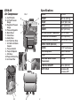
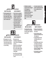
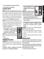
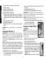
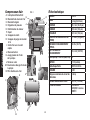
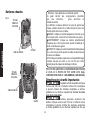
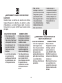
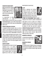
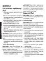
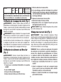
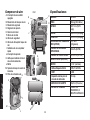
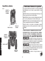
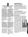
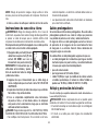
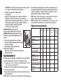
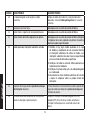
E810-4V
Air Compressor
A. On/Off Switch
B. Air Tank Pressure
Gauge
C. Regulated Pressure
Gauge
D. Pressure Regulator
E. Motor Reset
F. Check Valve
G. Safety Valve
H. Air Tank Drain Valve
I. Air Outlet with Quick
Coupler
J. Pressure Switch
K. Pump Oil Dipstick
L. Site Glass
M. Pump Oil Drain Plug
N. Air Intake Filter
J
D
B
C
A
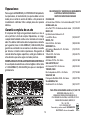
Specifications
MODEL E810-4V
WEIGHT 56.5 lbs. (25.6 kg)
HEIGHT 16.75" (501.7 mm)
WIDTH 18.5" (469.9 mm)
LENGTH 18.0" (457.2 mm)
AIR TANK CAPACITY (GALLONS) 4.0 (15.1 liters)
APPROX CUT-IN PRESSURE
95 PSI (655 kPa)
APPROX. CUT-OUT PRESSURE
125 PSI (861.8 kPa)
SCFM @ 100 PSI (689.5 kPa) 3.8
MOTOR 1.1 HP (continuous)
Volts/Amps/Hertz 120V/14 A/60 Hz.
RPM 3400
Minumum Branch Circuit
Requirement
15 Amp
PUMP OIL CAPACITY 12 oz. (354.9 ml)
DUTY CYCLE 5 minutes ON,
5 minutes OFF
E
K
M
F
N
G
FIG. 1
H
I
L

3
English
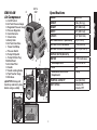
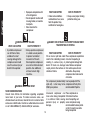
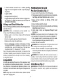
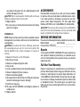
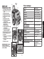
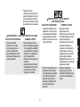
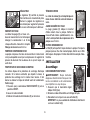
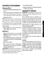
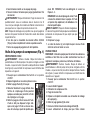
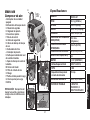
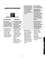
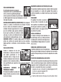
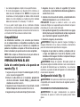
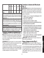
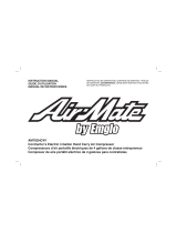
EM810-4M
Air Compressor
A. On/Off Switch
B. Air Tank Pressure Gauge
C. Regulated Pressure Gauge
D. Pressure Regulator
E. Quick Connects
F. Check Valve
G. Safety Valve
H. Air Tank Drain Valve
I. Power Cord Wrap
J. Pressure Switch
K. Pump Oil Dipstick
L. Pump Oil Drain Plug
M. Motor Reset
N. Air Intake Filter
O. Handle
P. Handle Locking Knobs
Q. Top Panel for Cargo
R. Site Glass
CAUTION: Always pull
handle up and lock in place
before using as a dolly.
Specifications
MODEL EM810-4M
WEIGHT 80 lbs. (36.3 kg)
HEIGHT 20.0" (508.0 mm)
WIDTH 18.5" (469.9 mm)
LENGTH 23 .0" (584.2 mm)
AIR TANK CAPACITY (GALLONS) 4.0 (15.1 liters)
APPROX CUT-IN PRESSURE
95 PSI (655 kPa)
APPROX. CUT-OUT PRESSURE
125 PSI (861.8 kPa)
SCFM @ 100 PSI (689.5 kPa) 3.8
MOTOR 1.1 HP (continuous)
Volts/Amps/Hertz 120V/14 A/60 Hz.
RPM 3400
Minumum Branch Circuit
Requirement
15 Amp
PUMP OIL CAPACITY 12 oz. (354.9 ml)
DUTY CYCLE 5 minutes ON,
5 minutes OFF
H
K
P
M
F
L
I
J
A
B
D
C
E
Q
O
NOT A
STEP
G
N
R

4
English
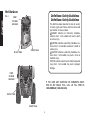
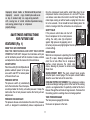
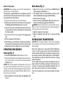
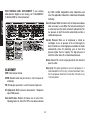
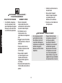
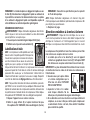
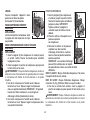
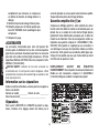
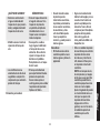
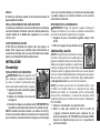
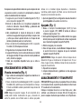
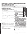
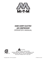
PUMP
CYLNDER
AND HEAD
PUMP
CYLNDER
AND HEAD
Hot Surfaces
FIG. 2
CHECK VALVE
CHECK VALVE
OUTLET TUBE
OUTLET TUBE
Definitions: Safety Guidelines
Definitions: Safety Guidelines
The definitions below describe the level of severity
for each signal word. Please read the manual and
pay attention to these symbols.
DANGER: Indicates an imminently hazardous
situation which, if not avoided, will result in death
or serious injury.
WARNING: Indicates a potentially hazardous situ-
ation which, if not avoided, could result in death or
serious injury.
CAUTION: Indicates a potentially hazardous situ-
ation which, if not avoided, may result in minor or
moderate injury.
NOTICE: Indicates a practice not related to personal
injury which, if not avoided, may result in property
damage.
IF YOU HAVE ANY QUESTIONS OR COMMENTS ABOUT
THIS OR ANY E
M
GLO TOOL, CALL US TOLL FREE AT:
1-888-88EMGLO (1-888-883-6456).

5
English
Important Safety Instructions
This product contains chemicals known to the State
of California to cause cancer, and birth defects or other reproduc-
tive harm. Wash hands after handling.
Some dust contains chemicals known to the State of
California to cause cancer, birth defects or other reproductive harm
such as asbestos and lead in lead based paint.
To reduce the risk of injury, read the
instruction manual.
SAVE THESE INSTRUCTIONS
DANGER: RISK OF EXPLOSION OR FIRE
WHAT CAN HAPPEN HOW TO PREVENT IT
• Itisnormalforelectrical
contacts within the motor
and pressure switch to
spark.
• Alwaysoperatethecom-
pressor in a well ventilated
area free of combustible
materials, gasoline or sol-
vent vapors.
• Ifelectricalsparksfrom
compressor come into
contact with flammable
vapors, they may ignite,
causing fire or explosion.
• Ifsprayingflammablemate-
rials, locate compressor
at least 20' (6.1 m) away
from spray area. An addi-
tional length of hose may be
required.
• Storeflammablematerialsin
a secure location away from
compressor.
• Restrictinganyofthe
compressor ventilation
openings will cause seri-
ous overheating and could
cause fire.
• Neverplaceobjectsagainst
or on top of compressor.
• Operatecompressorin
an open area at least 12"
(30.5 cm) away from any
wall or obstruction that
would restrict the flow of
fresh air to the ventilation
openings.
• Operatecompressorina
clean, dry well ventilated
area. Do not operate unit
indoors or in any confined
area. Store indoors.
• Unattendedoperationof
this product could result in
personalinjuryorproperty
damage. To reduce the
risk of fire, do not allow
the compressor to operate
unattended.
• Always remain in atten-
dance with the product
when it is operating.
• Alwaysturn off and unplug
unit when not in use.

6
English
DANGER: RISK TO BREATHING (ASPHYXIATION)
WHAT CAN HAPPEN HOW TO PREVENT IT
• Thecompressedairdirectly
from your compressor is not
safe for breathing. The air
stream may contain carbon
monoxide, toxic vapors,
or solid particles from the
air tank. Breathing these
contaminant's can cause
seriousinjuryordeath.
• Neveruseairobtained
directly from the compressor
to supply air for human
consumption. The
compressor is not equipped
with suitable filters and in-line
safety equipment for human
consumption.
•Exposuretochemicals
in dust created by
power sanding, sawing,
grinding, drilling, and other
construction activities may
be harmful.
• Sprayedmaterialssuchas
paint, paint solvents, paint
remover, insecticides, weed
killers, may contain harmful
vapors and poisons.
• Workinanareawithgood
cross ventilation. Read and
follow the safety instructions
provided on the label or
safety data sheets for the
materials you are spraying.
Always use certified safety
equipment: OSHA/MSHA/
NIOSH respiratory protection
designed for use with your
specific application.
WARNING: RISK OF BURSTING
On February 26, 2002, the U.S. Consumer Product Safety
Commission published Release # 02-108 concerning air com-
pressor tank safety:
Air compressor receiver tanks do not have an infinite life. Tank
life is dependent upon several factors, some of which include
operating conditions, ambient conditions, proper installations,
field modifications, and the level of maintenance. The exact
effect of these factors on air receiver life is difficult to predict.
If proper maintenance procedures are not followed, internal
corrosion to the inner wall of the air receiver tank can cause
the air tank to unexpectedly rupture allowing pressurized air
to suddenly and forcefully escape, posing risk of injury to
consumers.
Your compressor air tank must be removed from service by the
end of the year shown on your tank warning label.
The following conditions could lead to a weakening of the air
tank, and result in a violent air tank explosion:
WHAT CAN HAPPEN HOW TO PREVENT IT
• Failuretoproperlydrain
condensed water from
air tank, causing rust and
thinning of the steel air tank.
• Drainairtankdailyorafter
each use. If air tank develops
a leak, replace it immediately
with a new air tank or replace
the entire compressor.

7
English
• Modificationsorattempted
repairs to the air tank.
• Neverdrillinto,weld,ormake
any modifications to the
air tank or its attachments.
Never attempt to repair a
damaged or leaking air tank.
Replace with a new air tank.
• Unauthorizedmodifications
to the safety valve or any
other components which
control air tank pressure.
• Theairtankisdesigned
to withstand specific
operating pressures. Never
makeadjustmentsor
parts substitutions to alter
the factory set operating
pressures.
Attachments & accessories:
• Exceedingthepressure
rating of air tools, spray
guns, air operated
accessories, tires and other
inflatables can cause them
to explode or fly apart, and
couldresultinseriousinjury.
• Followtheequipment
manufacturers
recommendation and never
exceed the maximum
allowable pressure rating
of attachments. Never use
compressor to inflate small
lowpressureobjectssuch
as children’s toys, footballs,
basketballs, etc.
Tires:
• Overinflationoftirescould
result in serious injury and
property damage.
• Use a tire pressure gauge
to check the tires pressure
before each use and while
inflating tires; see the tire
sidewall for the correct tire
pressure.
NOTE: Air tanks, compressors
and similar equipment used to
inflate tires can fill small tires
very rapidly. Adjust pressure
regulator on air supply to no
more than the rating of the
tire pressure. Add air in small
increments and frequently
use the tire gauge to prevent
over inflation.
WARNING: RISK OF ELECTRICAL SHOCK
ELECTRICAL
Refer to all safety instructions before using unit. Observe
extension cord safety instructions if necessary. Always move
the On/Off switch (A) to the OFF position before removing the
plug from the outlet.

8
English
WHAT CAN HAPPEN HOW TO PREVENT IT
• Your air compressor is
powered by electricity.
Like any other electrically
powered device, If it is not
used properly it may cause
electric shock.
• Never operate the
compressor outdoors
when it is raining or in wet
conditions.
• Never operate compressor
with protective covers
removed or damaged.
• Repairs attempted by
unqualified personnel can
resultinseriousinjuryor
death by electrocution.
• Any electrical wiring
or repairs required on
this product should
be performed by an
authorized service center
in accordance with national
and local electrical codes.
• Electrical Grounding:
Failure to provide
adequate grounding to
this product could result
inseriousinjuryordeath
from electrocution. See
Grounding Instructions
under Installation.
• Make certain that the
electrical circuit to which the
compressor is connected
provides proper electrical
grounding, correct voltage
and adequate fuse
protection.
WARNING: RISK FROM FLYING OBJECTS
WHAT CAN HAPPEN HOW TO PREVENT IT
• Thecompressedairstream
can cause soft tissue
damage to exposed skin
and can propel dirt, chips,
loose particles and small
objectsathighspeed,
resulting in property
damageorpersonalinjury.
• Always wear certified safety
equipment: ANSI Z87.1 eye
protection (CAN/CSA Z94.3)
with side shields when using
the compressor.
• Neverpointanynozzleor
sprayer toward any part of
the body or at other people
or animals.
• Alwaysturnthecompressor
off and bleed pressure
from the air hose and air
tank before attempting
maintenance, attaching tools
or accessories.

9
English
WARNING: RISK OF HOT SURFACES
WHAT CAN HAPPEN HOW TO PREVENT IT
• Touchingexposedmetal
such as the compressor
head, engine head, engine
exhaust or outlet tubes, can
result in serious burns.
• Nevertouchanyexposed
metal parts on compressor
during or immediately after
operation. Compressor
will remain hot for several
minutes after operation.
• Donotreacharound
protective shrouds or
attempt maintenance until
unit has been allowed to
cool.
WARNING: RISK FROM MOVING PARTS
WHAT CAN HAPPEN HOW TO PREVENT IT
• Movingpartssuchasthe
pulley, flywheel and belt can
causeseriousinjuryifthey
come into contact with you
or your clothing.
• Neveroperatethe
compressor with guards or
covers which are damaged or
removed.
• Keepyourhair,clothingand
gloves away from moving
parts.Looseclothes,jewelry,
or long hair can be caught in
moving parts.
• Airventsmaycovermoving
parts and should be avoided
as well.
• Attemptingtooperate
compressor with damaged
or missing parts or
attempting to repair
compressor with protective
shrouds removed can
expose you to moving parts
and can result in serious
injury.
• Anyrepairsrequiredonthis
product should be performed
by an authorized service
center.
WARNING: RISK OF UNSAFE OPERATION
WHAT CAN HAPPEN HOW TO PREVENT IT
• Unsafeoperationofyour
air compressor could lead
toseriousinjuryordeathto
you or others.
• Reviewandunderstandall
instructions and warnings in
this manual.
• Becomefamiliarwiththe
op eration and con trols of the
air compressor.
• Keepoperatingareaclear
of all persons, pets, and
obstacles.
• Keepchildrenawayfromthe
air compressor at all times.
• Donotoperatetheproduct
when fatigued or under the
influence of alcohol or drugs.
Stay alert at all times.
• Neverdefeatthesafetyfea
tures of this prod uct.

10
English
• Equipareaofoperationwith
a fire extinguisher.
• Donotoperatemachinewith
missing, broken, or un au tho-
rized parts.
•Neverstandonthe
compressor.
WARNING: RISK OF FALLING
WHAT CAN HAPPEN HOW TO PREVENT IT
• Aportablecompressor
can fall from a table,
workbench or roof
causing damage to the
compressor and could
resultinseriousinjuryor
death to the operator.
• Alwaysoperatecompressor
in a stable secure position
to prevent accidental
movement of the unit.
Never operate compressor
on a roof or other elevated
position. Use additional
air hose to reach high
locations.
WARNING: RISK FROM NOISE
NOISE CONSIDERATIONS
Consult local officials for information regarding acceptable
noise levels in your area. To reduce excessive noise, use
vibration mounts or silencers, relocate the unit or construct total
enclosures or baffle walls. Contact an authorized service center
or call 1-888-88EMGLO (1-888-883-6456) for assistance.
WHAT CAN HAPPEN HOW TO PREVENT IT
• Undersomeconditions
and duration of use, noise
from this product may
contribute to hearing loss.
• Always wear properhearing
protection during use.
DANGER: RISK OF INJURY OR PROP ER TY DAMAGE WHEN
TRANSPORTING OR STORING
WHAT CAN HAPPEN HOW TO PREVENT IT
Oil can leak or spill and could
result in fire or breathing hazard,
resulting in serious injury or
death. Oil leaks can damage
carpet, paint or other surfaces in
vehicles or trailers.
Place compressor on protective
mat when transporting to
protect against damage from
leaks. Remove compressor
from vehicle upon arrival at
destination. Always keep
compressor level and never lie
on its side.
The compressor (wheeled dolly
style unit). is too heavy to be
lifted by one person.
Use two people to lift the
compressor. Lift only from
recommended lift points.
Unsecured compressor can
move when being transported
in a vehicle or trailer, causing
personal injury or property
damage.
Place compressor on
flat horizontal surface
when transporting and
secure compressor using
recommended tie-down points
so that it cannot move while
being transported.

11
English
Improperly locked handle or
improperly secured cargo
on top of wheeled dolly can
shift, causing loss of control
and causing personal injury or
property damage.
Extend handle fully and lock
handle in place and secure
cargo on top panel with
retention straps before moving
compressor.
SAVE THESE INSTRUCTIONS
FOR FUTURE USE
FEATURES (Fig. 1)
KNOW YOUR AIR COMPRESSOR
READ THIS OWNER’S MANUAL AND SAFETY RULES BEFORE
OPERATING YOUR UNIT. Compare the illustrations with your
unit to familiarize yourself with the location of various controls
andadjustments.Savethismanualforfuturereference.
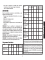
ON/OFF SWITCH
Place this switch (A) in the ON position to
A
J
provide automatic power to the pres-
sure switch and OFF to remove power
at the end of each use.
PRESSURE SWITCH
The pressure switch (J) automatically
starts the motor when the air tank pres-
sure drops below the factory set cut-in pressure. It stops the
motor when the air tank pressure reaches the factory set cut-
out pressure.
PRESSURE RELEASE VALVE
The pressure release valve located on the side of the pressure
switch, is designed to automatically release compressed air
from the compressor head and the outlet tube when the air
compressor reaches cut-out pressure or is shut off. The pres-
sure release valve allows the motor to restart freely. When the
motor stops running, air will be heard escaping from this valve
for a few seconds. No air should be heard leaking when the
motor is running or after the unit reaches cut-out pressure.
SAFETY VALVE
G
If the pressure switch does not shut off
the air compressor at its cut-out pressure
setting, the safety valve (G) will protect
against high pressure by popping out at
its factory set pressure (slightly higher than the pressure switch
cut-out setting).
CHECK VALVE
F
When the air compressor is operating, the check
valve (F) is open, allowing compressed air to
enter the air tank. When the air compressor
reaches cut-out pressure, the check valve
closes, allowing air pressure to remain inside
the air tank.
QUICK-CONNECT BODY: The quick connect body accepts
industrial quick connect plugs. The two quick connect bodies
allow the use of two tools at the same time.
COOLING SYSTEM (NOT SHOWN): This compressor contains
an advanced design cooling system. At the heart of this cooling
system is an engineered fan. It is perfectly normal for this fan to
blow air through the vent holes in large amounts. You know that
the cooling system is working when air is being expelled.
TANK PRESSURE GAUGE
The tank pressure gauge (B) indicates
the reserve air pressure in the tank.

12
English
OUTLET PRESSURE GAUGE
D
B
C
The outlet pressure gauge (C) indi-
cates the air pressure available at the
outlet side of the regulator. This pres-
sure is controlled by the regulator and
is always less than or equal to the
tank pressure.
REGULATOR
B D
E
C
The regulator (D) controls the air pres-
sure shown on the outlet pressure
gauge. Turn regulator knob clockwise to increase pressure and
counterclockwise to decrease pressure.
DRAIN VALVE
The drain valve (H) is located at the base
H
of the air tank and is used to drain con-
densation at the end of each use.
See
Draining Air Tank under Maintenance.
AIR COMPRESSOR PUMP
The pump compresses air into the air tank. Working air is not
available until the compressor has raised the air tank pressure
above that required at the air outlet.
MOTOR OVERLOAD PROTECTOR
This motor has a manual thermal overload protector. If the
motor overheats for any reason, the overload protector will shut
off the motor. The motor must be allowed to cool down before
restarting. To restart:
1. Ensure the On/Off switch (A) is in the OFF position.
2. Allow the motor to cool.
3. Depress the reset button (E) on the motor.
SITE GLASS
L
The crank case (L) is full when the oil level
reaches the halfway point in the site glass.
OIL DIPSTICK
The oil dipstick (K) indicates the amount of
oil in the pump. Check pump oil daily, see
Compressor Pump Oil under Maintenance.
AIR INTAKE FILTER
The filter (M) is designed to clean air entering
the pump. To ensure the pump continually
receives a clean, cool, and dry air supply the filter must always be
clean and the filter intake must be free from obstructions.
INSTALLATION
Assembly
M
K
INSTALLING HOSES
WARNING: Risk of unsafe operation.
Firmly grasp hose in hand when installing or
disconnecting to prevent hose whip.
1. Ensure regulated pressure gauge reads
0 PSI (0 kPa).
2. Apply sealant tape to hose threads.
3. Assemble hose to air outlet (E). IMPORTANT: Do not assemble
splitters directly to the air outlet (E).
NOTE: Assembling quick connect bodies to air outlet (E) and quick
connect plugs to hose ends make connecting and disconnecting
hoses simple and easy. Quick connect bodies and plugs are
available for purchase from your local dealer or authorized
service center.
DISCONNECTING HOSES
WARNING: Risk of unsafe operation. Firmly grasp hose in hand
when installing or disconnecting to prevent hose whip.

13
English
1. Ensure regulated pressure gauge reads 0 PSI (0 kPa).
2. Remove hose(s) from air outlet(s) (E).
Lubrication and Oil
NOTICE: The compressor was shipped without oil in the crankcase.
A small amount of oil may be present in the pump upon receipt of
the air compressor. This is due to testing and does not mean the
pump contains oil. Do not attempt to operate this air compressor
without first adding oil to the crankcase. Serious damage can
result from even limited operation unless filled with oil and broken
in correctly. Closely follow Initial Set-up under Operation.
NOTICE: Multi-viscosity motor oils, like 10W30, should not be
used in an air compressor. They leave carbon deposits on critical
components, thus reducing performance and compressor life. Use
ISO 100/SAE40, non-detergent, premium air compressor oil only.
1. Place unit on a level surface.
2. Remove dipstick (K) and slowly add
ISO 100/SAE40, non-detergent, premium
air compressor oil (supplied). NOTE: See
Specifications for pump oil capacity.
NOTICE: Risk of unsafe operation. Overfilling with
oil will cause premature compressor failure. Do
not overfill.
3. Replace dipstick.
Grounding Instructions
WARNING: Risk of electrical shock. In the event of a short
circuit, grounding reduces the risk of shock by providing an escape
wire for the electric current. This air compressor must be properly
grounded.
The portable air compressor is equipped with a cord having a
grounding wire with an appropriate grounding plug.
1. The cord set and plug (O) with this unit
P
O
Q
contains a grounding pin (P). This
plug MUST be used with a grounded
outlet (Q).
IMPORTANT: The outlet being used must
be installed and grounded in accordance
with all local codes and ordinances.
2. Ensure the outlet being used has the same configuration as
the grounded plug. DO NOT USE AN ADAPTER.
3. Inspect the plug and cord before each use. Do not use if there
are signs of damage.
4. If these grounding instructions are not completely understood,
or if in doubt as to whether the compressor is properly
grounded, have the installation checked by a qualified
electrician.
DANGER: Risk of electrical shock. IMPROPER GROUNDING
CAN RESULT IN ELECTRICAL SHOCK.
• Donotmodifytheplugprovided.Ifitdoesnotfittheavailable
outlet, a correct outlet should be installed by a qualified
electrician.
• RepairstothecordsetorplugMUSTbemadebyaqualified
electrician.
Extension Cords
Using extension cords is not recommended. The use of extension
cords will cause voltage to drop resulting in power loss to the
motor and overheating.
Instead of using an extension cord, increase the working reach of
the air hose by attaching another length of hose to its end. Attach
additional lengths of hose as needed.
If an extension cord must be used, be sure it is:

14
English
• a 3wire extension cord that has a 3blade grounding
plug, and a 3-slot receptacle that will accept the plug on
the product
• ingoodcondition
• nolongerthan50feet(15,2m)
• 12gauge(AWG)orlarger.(Wiresizeincreasesasgaugenum-
ber decreases. 10 AWG and 8 AWG may also be used. DO
NOT USE 14 OR 16 AWG.)
Voltage and Circuit Protection
Refer to the Voltage and Minimum Branch Circuit Requirements
under Specifications.
CAUTION: Certain air compressors can be operated on a
14 amp circuit if the following conditions are met.
• Voltage supply to circuit must comply with the National
Electrical Code.
• Circuitisnotusedtosupplyanyotherelectricalneeds.
• Extensioncordscomplywithspecifications.
• Circuitis equipped witha 14 Amp circuit breaker or14 Amp
time delay fuse. NOTE: If compressor is connected to a circuit
protected by fuses, use only time delay fuses. Time delay fuses
should be marked “D” in Canada and “T” in the US.
If any of the above conditions cannot be met, or if operation of the
compressor repeatedly causes interruption of the power, it may be
necessary to operate it from a 20 amp circuit. It is not necessary
to change the cord set.
Compatibility
Air tools and accessories that are run off the compressor must
be compatible with petroleum-based products. If you suspect
that a material is not compatible with petroleum products, an air
line filter for removal of moisture and oil vapor in compressed air
is required.
NOTE: Always use an air line filter to remove moisture and oil
vapor when spraying paint.
PREPARATION FOR USE
Pre-Start Checklist (Fig. 1)
1.
Ensure the On/Off switch (A) is in the OFF position.
2.
Plug the power cord into the correct branch circuit receptacle.
See Voltage and Circuit Protection under Installation.
3. Ensure air tank is drained, see Draining Air Tank under
Maintenance.
4. Ensure the drain valve (H) is closed.
5. Ensure safety valve (G) is functioning properly, see Checking
Safety Valve under Maintenance.
6. Check pump oil level, see Compressor Pump Oil under
Maintenance.
CAUTION:
Do not operate without oil or with inadequate oil. Emglo
is not responsible for compressor failure caused by inadequate oil.
7. Turn regulator knob (D) counterclockwise until fully closed.
Ensure regulated pressure gauge reads 0 PSI (0 kPa).
8. Attach hose and accessories.
WARNING: Risk of unsafe operation. Firmly grasp hose in hand
when installing or disconnecting to prevent hose whip.
9. Ensure all covers and labels are in place, legible (for labels)
and securely mounted. Do not use compressor until all items
have been verified.
WARNING: Risk of bursting. Too much air pressure causes a
hazardous risk of bursting. Check the manufacturer’s maximum
pressure rating for air tools and accessories. The regulator outlet
pressuremustneverexceedthemaximumpressurerating.
Initial Set-up
(Fig. 1)
WARNING: Do not operate this unit until you read and understand
this instruction manual for safety, operation and maintenance
instructions.

15
English
BREAK-IN PROCEDURE
WARNING:
Serious damage may result if the following break-in
instructions are not closely followed.
This procedure is required before the air compressor is put into
service for the first time and when the check valve or a compres-
sor pump/motor has been replaced.
1. Ensure the On/Off switch (A) is in the OFF position.
2.
Plug the power cord into the correct branch circuit receptacle.
See Voltage and Circuit Protection under Installation.
3. Open the drain valve (counterclockwise) fully to permit air to
escape and prevent air pressure build up in the air tank during
the break-in period.
4. Move the On/Off switch to the ON position. The compressor will
start.
5. Run the compressor for 20 minutes.
6. After 20 minutes, close the drain valve by turning clockwise.
The tank will fill to cut-out pressure and the motor will stop.
7. Compressed air will be available until it is used or bled off.
OPERATING PROCEDURES
Start-up (Fig. 1)
1. Follow Pre-Start Checklist under Preparation for Use.
2. Move the On/Off switch to the ON position and allow tank pres-
sure to build. Motor will stop when tank pressure reaches
cut-out pressure.
NOTICE: Risk of unsafe operation. Compressed air from the unit
may contain wa ter condensation and oil mist. Do not spray un fil-
tered air at an item that could be damaged by moisture. Some air
op er ated tools or de vic es may require filtered air. Read the in struc-
tions for the air tool or device.
3.Adjustregulator(D)todesiredsetting.SeeRegulator under
Features.
Shut-down (Fig. 1)
1 Move On/Off switch (A) is in the OFF position. NOTE: If finished
using compressor, follow Steps 2 - 6.
2. Turn regulator knob (D) counterclockwise until fully closed.
Ensure regulated pressure gauge reads 0 PSI (0 kPa).
3. Remove hose and accessory.
4. Drain the air tank,
see Draining Air Tank under Maintenance
.
Ensure air tank pressure gauge reads 0 PSI (0 kPa).
WARNING: Risk of bursting. Drain air tank daily. Water will con-
dense in air tank. If not drained, water will corrode and weaken the
air tank causing a risk of air tank rupture.
5. Allow the compressor to cool down.
6. Wipe air compressor clean and store in a safe, non-freezing
area.
STORAGE AND TRANSPORTING
CAUTION: Risk of property damage. In order to avoid damaging
the air compressor, do not allow the unit to be tilted more than 10º
when operating.
Place the air compressor in a clean, dry and well ventilated area
at least 12" (30.5 cm) away from the wall or other obstructions
that will interfere with the flow of air. Keep the compressor away
from areas that have dirt and/or volatile fumes in the atmosphere.
These impurities may clog the intake filter and valves, causing
inefficient operation.
The air compressor pump and shroud are designed to allow for
proper cooling. The ventilation openings on the compressor are
necessary to maintain proper operating temperature. Do not
place rags or other containers on or near these openings.
Place the air compressor on a flat surface resting on the rubber
feet.

16
English
TRANSPORTING
When transporting the compressor in
a vehicle, trailer, etc., ensure that the
tank is drained and the unit is secured
and placed on a flat horizontal sur-
face. NOTE: Use recommended tie
down points (U) when transporting.
Use care when driving so to avoid
tipping the unit over in the vehicle.
Damage can occur to the unit orsur-
rounding items if unit is tipped.
LIFTING
Always use two people when lifting and lift from the recom-
mended lift points (V).
FOR HAND CARRY COMPRESSOR ONLY
MOVING
When moving the compressor, grasp the handle and carry the
compressor as close to the body as possible.
FOR WHEELED DOLLY STYLE COMPRESSOR ONLY
MOVING
1. Grasp handle (O) of compressor and pull up until it stops. Turn
knobs to lock handle in place.
2. Grasp handle and tilt compressor so unit can be rolled on the
tires.
WARNING: Risk of unsafe operation. Ensure proper footing and
use caution when rolling compressor so that unit does not tip or
cause loss of balance.
3. When location is reached slowly lower compressor to
ground. Always store compressor in a horizontal position.
NOTE: Should the unit tip over, hard starting and smoking will
occur due to oil spillage.
4. When location is reached slowly lower compressor to
ground. Always store compressor in a horizontal position.
DOLLY FEATURE
1. Grasp handle (O) of compressor and
pull up until it stops. Turn knobs to lock
handle in place. IMPORTANT : Always
pull handle up and lock in place before
using as a dolly.
2. Place cargo onto top panel of
compressor.
3. Secure cargo to top panel with retention straps. Hook cargo
retention straps into positioning holes in top panel.
NOTE: Retention straps to secure cargo may be purchase
from a local hardware store or home
center in a variety of sizes.
CAUTION: Risk of unsafe operation. Do not
transport unsecured cargo.
CAUTION: Risk of unsafe operation. Load
limitis100lbs(45.4kg).donotexceed.
4. With cargo secured, grasp handle and tilt
compressor so unit can be rolled on the
tires.
WARNING: Risk of unsafe operation. Ensure proper footing
and use caution when rolling compressor so that unit does not
tip or cause loss of balance.
5. When location is reached slowly lower compressor
to ground. Always store compressor in a horizontal
position.
V
O
U

17
English
MAINTENANCE
The following procedures must be followed when maintenance or
service is performed on the air compressor.
1. Ensure On/Off switch is in the OFF position.
2. Remove air compressor plug from outlet.
3. Drain air tank.
4. Allow air compressor to cool down before starting service.
NOTE: All compressed air systems contain maintenance parts
(e.g., oil, filters, separators) that are periodically replaced. These
used parts may contain substances that are regulated and must be
disposed of in accordance with local, state, and federal laws and
regulations.
NOTE: Take note of the positions and locations of parts during
disassembly to make reassembly easier.
NOTE: Any service operations not included in this section should
be performed by an authorized service center.
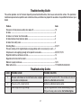
Maintenance Chart
Procedure Daily Weekly Monthly 1 year
or 200
Hours
see tank
warning label
Check safety valve
X
Inspect air filter
+
X
Drain air tank
X
Check pump oil level
X
Change pump oil**
+
X
Oil leak inspection
X
Check for unusual noise/
vibration
X
Check for air leaks*
X
Procedure Daily Weekly Monthly 1 year
or 200
Hours
see tank
warning label
Clean compressor exterior
X
Remove tank from service
X
** The pump oil must be changed after the first 20 hours of operation.
Thereafter, when using
ISO 100/SAE40, non-detergent, premium air
compressor oil
, change oil every 200 hours of operation or once a year,
whichever comes first.
+ Perform more frequent in dusty or humid conditions
Remove tank from service. For more information, call our Customer
Care Center at
1-888-88EMGLO (1-888-883-6456)
Checking Safety Valve (Fig. 1)
WARNING: Hot surfaces. Risk of burn. Aftercooler, pump head,
and surrounding parts are very hot, do not touch (see the Hot
Surfaces identified in Fig. 2). Allow compressor to cool prior to
servicing.
WARNING: Risk of bursting. If the safety valve does not work
properly, over-pressurization may occur, causing air tank rupture or
anexplosion.
Before starting compressor, pull the ring on the safety valve to
make sure that the safety valve operates freely. If the valve is
stuck or does not operate smoothly, it must be replaced with the
same type of valve.
Checking Air Filter Element (Fig. 1)
WARNING: Hot surfaces. Risk of burn. Aftercooler, pump head,
and surrounding parts are very hot, do not touch (see the Hot
Surfaces identified in Fig. 2). Allow compressor to cool prior to
servicing.

18
English
1. Ensure the On/Off switch (A) is in the OFF position.
2. Allow unit to cool.
3. Remove air filter (M) from unit.
4. Carefully pry filter top from base.
5. Remove element from filter base.
6. If element needs cleaning, blow out with air. Replace if
needed. Purchase replacement parts from your local dealer or
authorized service center. Always use identical replacement
parts.
7. Place element back in filter base.
8. Snap filter top to filter base.
9. Reassemble air filter to unit. Ensure exhaust outlet points
down.
CAUTION: Risk of unsafe operation. Do not operate without air
inlet filter
Draining Air Tank (Fig. 1)
WARNING: Risk of unsafe operation. Risk from noise. Air
tanks contain high pressure air. Keep face and other body parts
away from outlet of drain. Use safety glasses [ANSI Z87.1 (CAN/
CSA Z94.3)] when draining as debris can be kicked up into face.
Use ear protection [ANSI S12.6 (S3.19)] as air flow noise is loud
when draining.
NOTE: All compressed air systems generate condensate that
accumulates in any drain point (e.g. tanks, filter, aftercoolers,
dryers). This condensate contains lubricating oil and/or
substances which may be regulated and must be disposed of in
accordance with local, state, and federal laws and regulations.
1. Ensure On/Off switch is in the OFF position.
2. Move compressor into an inclined position so drain valve (H)
is at the lowest point (this will assist in removing moisture,
dirt, etc. from air tanks)
3. Place a suitable container under the drain valve to catch
discharge.
4. Grasp knurled knob on drain valve.
5. Slowly rotate knob to gradually bleed air from air tank.
WARNING: Risk of bursting. Drain air tank daily. Water will con-
dense in air tank. If not drained, water will corrode and weaken the
air tank causing a risk of air tank rupture.
NOTICE: Risk of property damage. Drain water from air tank may
contain oil and rust, which can cause stains.
6. When air tank pressure gauge reads 10 PSI (68,9 kPa), rotate
valve to the fully open position.
7. Close drain valve when finished.
Compressor Pump Oil (Fig. 1)
M
K
L
CHECKING OIL
WARNING: Hot surfaces. Risk of burn.
Aftercooler, pump head, and surrounding parts
are very hot, do not touch (see the Hot Surfaces
identified in Fig. 2). Allow compressor to cool
prior to servicing.
1. Ensure On/Off switch is in the OFF position.
2. Place unit on a flat level surface.
3. Remove dipstick (K) and wipe clean.
4. Reinsert dipstick fully into oil fill port for a few
seconds to allow oil to collect on the dipstick.
5. Remove oil dipstick to read oil level. Oil should
not exceed top raised line on dipstick. If oil is
below lower mark, add ISO 100/SAE40, non-
detergent, premium air compressor oil and fol-
low Steps 4 - 6.
NOTE: When filling the crankcase, the oil flows
MAX
MIN

19
English
very slowly into the pump. If the oil is added too quickly, it will
overflow and appear to be full.
CAUTION: Risk of unsafe operation. Overfilling with oil will cause
premature compressor failure. Do not overfill.
6. Replace dipstick.
7.The crank case (L) is full when the oil level reaches the halfway
point in the site glass.
CHANGING OIL
NOTE: Pump oil contains substances that are regulated and must
be disposed of in accordance with local, state and federal laws
and regulations.
WARNING: Hot surfaces. Risk of burn. Aftercooler, pump head,
and surrounding parts are very hot, do not touch (see the Hot
Surfaces identified in Fig. 2). Allow compressor to cool prior to
servicing.
1. Ensure On/Off switch is in the OFF position.
2. Allow the unit to cool.
3. Remove air compressor plug from outlet.
4. Drain air tank.
5. Locate a suitable container under pump drain plug (L).
6. Remove the dipstick (K) from crank case.
7. Remove the oil drain plug (M).
8. Allow ample time for all oil to drain out. (Tilting the compressor
towards the drain plug will assist in draining.)
9. Install the oil drain plug.
10. Fill pump with ISO 100/SAE40, non-detergent, premium air
compressor oil.
11. Replace dipstick.
ACCESSORIES
Recommended accessories for use with your tool are available
for purchase from your local dealer or authorized service center.
If you need assistance in locating any accessory for your tool,
please contact E
m
glo Compressors, 701 East Joppa Road,
Baltimore, MD 21286 or call 1-888-88EMGLO (1-888-883-6456).
CAUTION: The use of any other accessory not recommended for
use with this tool could be hazardous. Use only accessories rated
equal to or higher than the rating of the air compressor.
SERVICE INFORMATION
Please have the following information available for all service calls:
Model Number ____________ Serial Number _________________
Date and Place of Purchase ______________________________
Repairs
To assure product SAFETY and RELIABILITY, repairs, maintenance
and adjustment should be performed by an authorized service
center or other qualified service personnel. Always use identical
replacement parts.
Full One Year Warranty
Emglo air compressors are warranted for one year from date of
purchase. We will repair, without charge, any defects due to faulty
materials or workmanship. For warranty repair information, call
1-888-88EMGLO (1-888-883-6456). This warranty does not apply
to accessories or damage caused where repairs have been made
or attempted by others. This warranty gives you specific legal
rights and you may have other rights which vary in certain states
or provinces.

20
English
FREE WARNING LABEL REPLACEMENT: If your warning
labels become illegible or are missing, call 1-888-88EMGLO
(1-888-883-6456) for a free replacement.
GLOSSARY
CFM: Cubic feet per minute.
SCFM: Standard cubic feet per minute; a unit of measure of
air delivery.
PSI: Pounds per square inch; a unit of measure of pressure.
kPa (kilopascal): Metric pressure measurement. 1 kilopascal
equal 1000 pascals.
Code Certification: Products that bear one or more of the
following marks: UL, CUL, ETL, CETL, have been evaluated
by OSHA certified independent safety laboratories and
meet the applicable Underwriters Laboratories Standards
for Safety.
Cut-In Pressure: While the motor is off, air tank pressure drops
when accessory is used. When the tank pressure drops to
a certain low level the motor will restart automatically. The
low pressure at which the motor automatically restarts is
called cut-in pressure.
Cut-Out Pressure: When an air compressor is turned on
and begins to run, air pressure in the air tank begins to
build. It builds to a certain high pressure before the motor
automatically shuts off, protecting your air tank from
pressure higher than its capacity. The high pressure at
which the motor shuts off is called cut-out pressure.
Branch Circuit: The circuit carrying electricity from electrical
panel to outlet.
Duty Cycle: For proper operation of your air compressor, it is
recommended that a 50% duty cycle be maintained; that is,
the air compressor should not run more than 5 minutes in any
10 minute period.

21
English
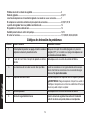
Troubleshooting Guide
This section provides a list of the more frequently encountered malfunctions, their causes and corrective actions. The operator or
maintenance personnel can perform some corrective actions, and others may require the assistance of a qualified technician or your
dealer.
Problem Code
Excessive air tank pressure-safety valve pops off ................................................................... 1,2
Air leaks ...................................................................................................................................3
Air leaks in air tank or at air tank welds .................................................................................. 4
Air leaks between head and valve plate .................................................................................5
Air leaks from safety valve .......................................................................................................6
Knocking Noise .........................................................................................................................6,16,17
Pressure reading on the regulated pressure gauge drops when an accessory is used ......7
Compressor is not supplying enough air to operate accessories ......................................... 8,9,10,11,12,15
Regulator knob has continuous air leak..................................................................................13
Regulator will not shut off air outlet ........................................................................................13
Moisture in pump crankcase ...................................................................................................14,18
Motor will not run .....................................................................................................................11,19,20,21,22,23,24,25,26
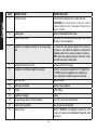
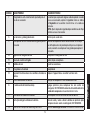
Troubleshooting Codes
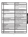
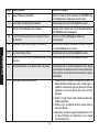
CODE POSSIBLE CAUSE POSSIBLE SOLUTION
1 Pressure switch does not shut off motor when compres-
sor reaches cut-out pressure
Set the On/Off switch to OFF, if the unit does not shut off
contact an authorized service center.
2 Pressure switch cut-out too high Contact an authorized service center.
3 Tube fittings are not tight enough Tighten fittings where air can be heard escaping. Check
fittings with soapy water solution. Do Not Overtighten.
Page is loading ...
Page is loading ...
Page is loading ...
Page is loading ...
Page is loading ...
Page is loading ...
Page is loading ...
Page is loading ...
Page is loading ...
Page is loading ...
Page is loading ...
Page is loading ...
Page is loading ...
Page is loading ...
Page is loading ...
Page is loading ...
Page is loading ...
Page is loading ...
Page is loading ...
Page is loading ...
Page is loading ...
Page is loading ...
Page is loading ...
Page is loading ...
Page is loading ...
Page is loading ...
Page is loading ...
Page is loading ...
Page is loading ...
Page is loading ...
Page is loading ...
Page is loading ...
Page is loading ...
Page is loading ...
Page is loading ...
Page is loading ...
Page is loading ...
Page is loading ...
Page is loading ...
Page is loading ...
Page is loading ...
Page is loading ...
Page is loading ...
Page is loading ...
Page is loading ...
Page is loading ...
Page is loading ...
Page is loading ...
Page is loading ...
Page is loading ...
Page is loading ...
Page is loading ...
Page is loading ...
Page is loading ...
-
 1
1
-
 2
2
-
 3
3
-
 4
4
-
 5
5
-
 6
6
-
 7
7
-
 8
8
-
 9
9
-
 10
10
-
 11
11
-
 12
12
-
 13
13
-
 14
14
-
 15
15
-
 16
16
-
 17
17
-
 18
18
-
 19
19
-
 20
20
-
 21
21
-
 22
22
-
 23
23
-
 24
24
-
 25
25
-
 26
26
-
 27
27
-
 28
28
-
 29
29
-
 30
30
-
 31
31
-
 32
32
-
 33
33
-
 34
34
-
 35
35
-
 36
36
-
 37
37
-
 38
38
-
 39
39
-
 40
40
-
 41
41
-
 42
42
-
 43
43
-
 44
44
-
 45
45
-
 46
46
-
 47
47
-
 48
48
-
 49
49
-
 50
50
-
 51
51
-
 52
52
-
 53
53
-
 54
54
-
 55
55
-
 56
56
-
 57
57
-
 58
58
-
 59
59
-
 60
60
-
 61
61
-
 62
62
-
 63
63
-
 64
64
-
 65
65
-
 66
66
-
 67
67
-
 68
68
-
 69
69
-
 70
70
-
 71
71
-
 72
72
-
 73
73
-
 74
74
-
 75
75


Ask a question and I''ll find the answer in the document
Finding information in a document is now easier with AI
in other languages
- français: Emglo EM810-4M Manuel utilisateur
- español: Emglo EM810-4M Manual de usuario
Related papers


Other documents
-
 Air Mate AM782HC4V User manual
-
Porter-Cable C2002 User manual
-
DeWalt D55166 User manual
-
Porter-Cable PCFP12656 Installation guide
-
Mi-T-M PORTABLE ELECTRICAIR COMPRESSOR Operating instructions
-
-
 Mi-T-M AC1-HE02-05M1 User guide
-
RIDGID OL50135A User manual
-
-
Bostitch BTFP02006 User manual

