Page is loading ...

Instruction manual
Manuel d’utilisation
Manual de instrucciones
SA350K
www.DeltaMachinery.com
Français (12)
Español (22)
INSTRUCTIVO DE OPERACIÓN, CENTROS DE SERVICIO
Y PÓLIZA DE GARANTÍA.
LÉASE ESTE
INSTRUCTIVO ANTES DE USAR EL PRODUCTO.
Bench Oscillating
spindle sander
Ponceuse d’établi à
broche oscillante
Lijadora de eje oscilante
de banco

TABLE OF CONTENTS
IMPORTANT SAFETY INSTRUCTIONS .....................2
SAFETY GUIDELINES - DEFINITIONS ......................2
GENERAL SAFETY RULES ........................................3
ADDITIONAL SPECIFIC SAFETY RULES ..................4
FUNCTIONAL DESCRIPTION ....................................6
CARTON CONTENTS .................................................6
ASSEMBLY ..................................................................7
OPERATION ................................................................9
TROUBLESHOOTING .................................................10
MAINTENANCE ...........................................................10
SERVICE ......................................................................10
ACCESSORIES ............................................................11
WARRANTY .................................................................11
FRANÇAIS ...................................................................12
ESPAÑOL .....................................................................22
2
IMPORTANT SAFETY INSTRUCTIONS
loot yna gnisu erofeb snoitcurtsni gnitarepo dna sgninraw lla dnatsrednu dna daeR
dewollof eb syawla dluohs snoituacerp ytefas cisab ,tnempiuqe ro sloot gnisu nehW .tnempiuqe ro
to reduce the risk of personal injury. Improper operation, maintenance or modification of tools
or equipment could result in serious injury and property damage. There are certain applications
for which tools and equipment are designed. DELTA® Power Equipment Corporation strongly
recommends that this product NOT be modified and/or used for any application other than for which it was
designed.
If you have any questions relative to its application DO NOT use the product until you have written DELTA® Power
Equipment Corporation and we have advised you. Contact us online at www.DeltaMachinery.com or by mail at
Technical Service Manager, DELTA® Power Equipment Corporation, 99 Roush St., Anderson, South Carolina 29625.
Information regarding the safe and proper operation of this tool is available from the following sources:
• Power Tool Institute, 1300 Sumner Avenue, Cleveland, OH 44115-2851or online at www.powertoolinstitute.org
• National Safety Council, 1121 Spring Lake Drive, Itasca, IL 60143-3201
• American National Standards Institute, www.ansi.org - ANSI01.1
Safety Requirements for Woodworking Machines
• U.S. Department of Labor regulations www.osha.gov
SAVE THESE INSTRUCTIONS!
SAFETY GUIDELINES - DEFINITIONS
It is important for you to read and understand this manual. The information it contains relates to protecting YOUR
SAFETY and PREVENTING PROBLEMS. The symbols below are used to help you recognize this information.
Indicates an imminently hazardous situation which, if not avoided, will result in death or
serious injury.
Indicates a potentially hazardous situation which, if not avoided, could result in death or
serious injury.
Indicates a potentially hazardous situation which, if not avoided, may result in minor or
moderate injury.
Used without the safety alert symbol indicates a potentially hazardous situation which, if not
avoided, may result in property damage.
Some dust created by power sanding, sawing, grinding, drilling, and other construction activi-
ties contains chemicals known to cause cancer, birth defects or other reproductive harm. Some
examples of these chemicals are:
• lead from lead-based paints,
• crystalline silica from bricks and cement and other masonry products, and
• arsenic and chromium from chemically-treated lumber.
Your risk from these exposures varies, depending on how often you do this type of work. To reduce your ex-
posure to these chemicals: work in a well ventilated area, and work with approved safety equipment, al ways
wear NIOSH/OSHA approved, properly fit ting face mask or res pi ra tor when us ing such tools.

GENERAL SAFETY RULES
Failure to follow these rules may result in serious personal injury.
3
24.
1. FOR YOUR OWN SAFETY, READ THE INSTRUCTION
MANUAL BEFORE OPERATING THE MACHINE. Learning
the machine’s application, limitations, and specic hazards
will greatly minimize the possibility of accidents and injury.
2. WEAR EYE AND HEARING PROTECTION. ALWAYS USE
SAFETY GLASSES. Everyday eyeglasses are NOT safety
glasses. USE CERTIFIED SAFETY EQUIPMENT. Eye
protection equipment should comply with ANSI Z87.1
standards. Hearing equipment should comply with ANSI
S3.19 standards.
3. WEAR PROPER APPAREL. Do not wear loose clothing,
gloves, neckties, rings, bracelets, or other jewelry which may
get caught in moving parts. Nonslip protective footwear is
recommended. Wear protective hair covering to contain long
hair.
4. DO NOT USE THE MACHINE IN A DANGEROUS
ENVIRONMENT. The use of power tools in damp or wet
locations or in rain can cause shock or electrocution. Keep
your work area well-lit to prevent tripping or placing arms,
hands, and ngers in danger.
5. MAINTAIN ALL TOOLS AND MACHINES IN PEAK
CONDITION. Keep tools sharp and clean for best and
safest performance. Follow instructions for lubricating
and changing accessories. Poorly maintained tools and
machines can further damage the tool or machine and/or
cause injury.
6. CHECK FOR DAMAGED PARTS. Before using the machine,
check for any damaged parts. Check for alignment of
moving parts, binding of moving parts, breakage of parts,
and any other conditions that may affect its operation. A
guard or any other part that is damaged should be properly
repaired or replaced with DELTA® or factory authorized
replacement parts. Damaged parts can cause further
damage to the machine and/or injury.
7. KEEP THE WORK AREA CLEAN. Cluttered areas and
benches invite accidents.
8. KEEP CHILDREN AND VISITORS AWAY. Your shop is a
potentially dangerous environment. Children and visitors
can be injured.
9. REDUCE THE RISK OF UNINTENTIONAL STARTING.
Make sure that the switch is in the “OFF” position before
plugging in the power cord. In the event of a power failure,
move the switch to the “OFF” position. An accidental start-
up can cause injury. Do not touch the plug’s metal prongs
when unplugging or plugging in the cord.
10. USE THE GUARDS. Check to see that all guards are in
place, secured, and working correctly to prevent injury.
11. REMOVE ADJUSTING KEYS AND WRENCHES BEFORE
STARTING THE MACHINE. Tools, scrap pieces, and other
debris can be thrown at high speed, causing injury.
12. USE THE RIGHT MACHINE. Don’t force a machine or
an attachment to do a job for which it was not designed.
Damage to the machine and/or injury may result.
13. USE RECOMMENDED ACCESSORIES. The use of
accessories and attachments not recommended by DELTA®
may cause damage to the machine or injury to the user.
14. USE THE PROPER EXTENSION CORD. Make sure
your extension cord is in good condition. When using an
extension cord, be sure to use one heavy enough to carry
the current your product will draw. An undersized cord will
cause a drop in line voltage, resulting in loss of power and
overheating. See the Extension Cord Chart for the correct
size depending on the cord length and nameplate ampere
rating. If in doubt, use the next heavier gauge. The smaller
the gauge number, the heavier the cord.
15. SECURE THE WORKPIECE. Use clamps or a vise to hold
the workpiece when practical. Loss of control of a workpiece
can cause injury.
16. FEED THE WORKPIECE AGAINST THE DIRECTION OF
THE ROTATION OF THE BLADE, CUTTER, OR ABRASIVE
SURFACE. Feeding it from the other direction will cause the
workpiece to be thrown out at high speed.
17. DON’T FORCE THE WORKPIECE ON THE MACHINE.
Damage to the machine and/or injury may result.
18. DON’T OVERREACH. Loss of balance can make you fall
into a working machine, causing injury.
19. NEVER STAND ON THE MACHINE. Injury could occur if
the tool tips, or if you accidentally contact the cutting tool.
20. NEVER LEAVE THE MACHINE RUNNING UNATTENDED.
TURN THE POWER OFF. Don’t leave the machine until it
comes to a complete stop. A child or visitor could be injured.
21. TURN THE MACHINE “OFF”, AND DISCONNECT THE
MACHINE FROM THE POWER SOURCE before installing
or removing accessories, changing cutters, adjusting or
changing set-ups. When making repairs, be sure to lock the
start switch in the “OFF” position. An accidental start-up
can cause injury.
22. MAKE YOUR WORKSHOP CHILDPROOF WITH
PADLOCKS, MASTER SWITCHES, OR BY REMOVING
STARTER KEYS. The accidental start-up of a machine by a
child or visitor could cause injury.
23. STAY ALERT, WATCH WHAT YOU ARE DOING, AND
USE COMMON SENSE. DO NOT USE THE MACHINE
WHEN YOU ARE TIRED OR UNDER THE INFLUENCE
OF DRUGS, ALCOHOL, OR MEDICATION. A moment of
inattention while operating power tools may result in injury.
USE OF THIS TOOL CAN GENERATE
AND DISBURSE DUST OR OTHER AIRBORNE
PARTICLES, INCLUDING WOOD DUST, CRYSTALLINE
SILICA DUST AND ASBESTOS DUST. Direct particles
away from face and body. Always operate tool in well
ventilated area and provide for proper dust removal.
Use dust collection system wherever possible.
Exposure to the dust may cause serious and permanent
respiratory or other injury, including silicosis (a serious
lung disease), cancer, and death. Avoid breathing the
dust, and avoid prolonged contact with dust. Allowing
dust to get into your mouth or eyes, or lay on your skin
may promote absorption of harmful material. Always
use properly fitting NIOSH/OSHA approved respiratory
protection appropriate for the dust exposure, and wash
exposed areas with soap and water.

ADDITIONAL SPECIFIC SAFETY RULES
Failure to follow these rules may result in serious personal injury.
1. DO NOT OPERATE THIS MACHINE until it is
completely assembled and installed according to
the instructions. A machine incorrectly assembled
can cause serious injury.
2. OBTAIN ADVICE from your supervisor, instructor, or
another qualied person if you are not thoroughly
familiar with the operation of this machine.
3. FOLLOW ALL WIRING CODES and recommended
electrical connections to prevent shock or
electrocution.
4. NEVER TURN THE MACHINE “ON” before clearing
the table/work area of all objects (tools, scraps of
wood, etc.).
5. NEVER TURN THE MACHINE “ON” with the
workpiece contacting the abrasive surface.
6. SECURE THE MACHINE to a supporting surface.
Vibration can cause the machine to slide, walk, or
tip over.
7. REPLACE SLEEVES WHEN WORN OR DAMAGED.
A torn or damaged sleeve could be unexpectedly
expelled from the machine if not replaced
8. PROPERLY SECURE SANDING DRUM on spindle
before operating.
9. DO NOT USE THE MACHINE for wet sanding
applications.
10. CLEAN THE MACHINE and dust collector
thoroughly when processing different types of
workpieces (wood, steel, or aluminum). Combining
wood and metal dust can create an explosion or re
hazard.
11. TO REDUCE THE RISK OF FIRE, do not sand or
polish magnesium.
12. HOLD WORKPIECE FIRMLY ON THE SANDER
TABLE. To prevent loss of control use a solid grip.
13. INSPECT MATERIALS FOR DEFECTS. Knots and
splinters can be thrown from the machine with great
force. Make sure defective materials are not used
on this spindle sander.
14. FOREIGN OBJECTS SUCH AS NAILS AND
STAPLES should be removed before sanding.
15. AVOID AWKWARD OPERATIONS AND HAND
POSITIONS. A sudden slip could cause a hand to
contact the abrasive sleeve.
16. KEEP TABLE INSERT IN PLACE. Use correctly
sized table insert for each sanding sleeve to reduce
risk of ngers being pinched or material being
pulled down.
17. ALWAYS FEED WORKPIECE AGAINST the
direction of the sanding belt rotation.
18. DO NOT SAND very small or very thin workpieces
that cannot be safely controlled. Loss of control of
the workpiece can result in injury.
19. TO MAINTAIN CONTROL, properly support long
or wide work-pieces.
20. NEVER PERFORM LAYOUT, ASSEMBLY, OR
SET-UP WORK on the table/work area when the
machine is running. A sudden slip could cause a
hand to move into the abrasive surface.
21. TURN THE MACHINE “OFF”, disconnect the
machine from the power source, and clean the
table/work area before leaving the machine. LOCK
THE SWITCH IN THE “OFF” POSITION to prevent
unauthorized use.
22. ADDITIONAL INFORMATION regarding the safe
and proper operation of power tools (i.e. a safety
video) is available from the Power Tool Institute,
1300 Sumner Avenue, Cleveland, OH 44115-2851
(www.powertoolinstitute.com). Information is also
available from the National Safety Council, 1121
Spring Lake Drive, Itasca, IL 60143-3201. Please
refer to the American National Standards Institute
ANSI 01.1 Safety Requirements for Woodworking
Machines and the U.S. Department of Labor OSHA
1910.213 regulations.
SAVE THESE INSTRUCTIONS.
Refer to them often and use them to instruct others.
4

GROUNDED OUTLET BOX
CURRENT
CARRYING
PRONGS
GROUNDING BLADE
IS LONGEST OF THE 3 BLADES
Fig. A Fig. B
GROUNDED OUTLET BOX
GROUNDING MEANS
ADAPTER
POWER CONNECTIONS
A separate electrical circuit should be used for your machines. This circuit should not be less than #12 wire and should
be protected with a 20 Amp time lag fuse. If an extension cord is used, use only 3-wire extension cords which have
3-prong grounding type plugs and matching receptacle which will accept the machine’s plug. Before connecting the
machine to the power line, make sure the switch (s) is in the “OFF” position and be sure that the electric current is of
the same characteristics as indicated on the machine. All line connections should make good contact. Running on low
voltage will damage the machine.
Do not expose the machine to rain or operate the machine in damp locations.
MOTOR SPECIFICATIONS
Your machine is wired for 120 volt, 60 HZ alternating current. Before connecting the machine to the power source,
make sure the switch is in the “OFF” position.
GROUNDING INSTRUCTIONS
This machine must be grounded while in use to protect the operator from electric shock.
1. All grounded, cord-connected machines:
In the event of a malfunction or breakdown, grounding provides a path of least resistance for electric current to
reduce the risk of electric shock. This machine is equipped with an electric cord having an equipment-grounding
conductor and a grounding plug. The plug must be plugged into a matching outlet that is properly installed and
grounded in accordance with all local codes and ordinances.
Do not modify the plug provided - if it will not t the outlet, have the proper outlet installed by a qualied electrician.
Improper connection of the equipment-grounding conductor can result in risk of electric shock. The conductor with
insulation having an outer surface that is green with or without yellow stripes is the equipment-grounding conductor.
If repair or replacement of the electric cord or plug is necessary, do not connect the equipment-grounding conductor
to a live terminal.
Check with a qualied electrician or service personnel if the grounding instruction are not completely understood, or
if in doubt as to whether the machine is properly grounded.
Use only 3-wire extension cords that have 3-prong grounding type plugs and matching 3-conductor receptacles that
accept the machine’s plug, as shown in Fig. A. Repair or replace damaged or worn cord immediately.
2. Grounded, cord-connected machines intended for use on a supply circuit having a nominal rating less than
150 volts:
If the machine is intended for use on a circuit that has an outlet that looks like the one illustrated in Fig. A , the
machine will have a grounding plug that looks like the plug illustrated in Fig. A. A temporary adapter, which looks like
the adapter illustrated in Fig. B may be used to connect this plug to a matching 2-conductor receptacle as shown
in Fig. B, if a properly grounded outlet is not available. The temporary adapter should be used only until a properly
grounded outlet can be installed by a qualied electrician. The green-colored rigid ear, lug, and the like, extending
from the adapter must be connected to a permanent ground such as a properly grounded outlet box. Whenever the
adapter is used, it must be held in place with a metal screw.
NOTE: In Canada, the use of a temporary adapter is not permitted by the Canadian Electric Code.
In all cases, make certain that the receptacle in question is properly grounded. If you are not sure,
have a qualified electrician check the receptacle.
5
MINIMUM GAUGE EXTENSION CORD
RECOMMENDED SIZES FOR USE WITH STATIONARY ELECTRIC MACHINES
Total
Ampere
Rating
0-6
0-6
0-6
0-6
6-10
6-10
6-10
6-10
10-12
10-12
10-12
10-12
12-16
12-16
12-16
Volts
120
120
120
120
120
120
120
120
120
120
120
120
120
120
120
Length of
Cord in
Feet
up to 25
25-50
50-100
100-150
up to 25
25-50
50-100
100-150
up to 25
25-50
50-100
100-150
up to 25
25-50
Gauge of Extension
Cord
18 AWG
16 AWG
16 AWG
14 AWG
18 AWG
16 AWG
14 AWG
12 AWG
16 AWG
16 AWG
14 AWG
12 AWG
14 AWG
12 AWG
GREATER THAN 50 FEET NOT RECOMMENDED
Fig. C
FUNCTIONAL DESCRIPTION
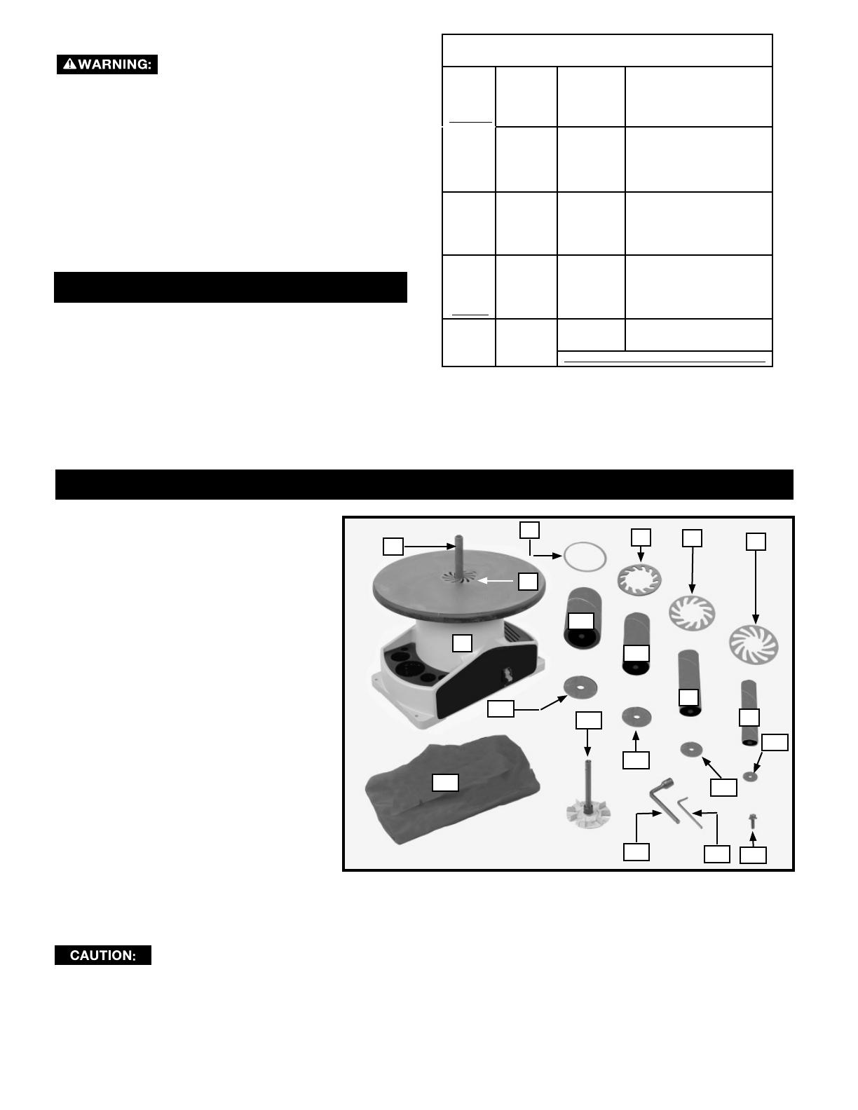
CARTON CONTENTS
2
1
20
4
3
15
11
19
5
10
14
18
6
9
7
8
13
17
12
16
EXTENSION CORDS
Use proper extension cords. Make
sure your extension cord is in good condition and is a
3-wire extension cord which has a 3-prong grounding
type plug and matching receptacle which will accept
the machine’s plug. When using an extension cord,
be sure to use one heavy enough to carry the current
of the machine. An undersized cord will cause a
drop in line voltage, resulting in loss of power and
overheating. Fig. C shows the correct gauge to use
depending on the cord length. If in doubt, use the
next heavier gauge. The smaller the gauge number,
the heavier the cord.
FOREWORD
The DELTA® Model SA350K has a large 18” diameter
castiron table to support large workpieces. This machine
has a heavy-duty motor assembly with a 1/4 H.P. direct
drive induction motor for quiet, and smooth operation.
NOTICE: The photo on the manual cover illustrates the current production model. All other illustrations contained in the
manual are representative only and may not depict the actual labeling or accessories included. These are intended to
illustrate technique only.
1. Bench Oscillating Spindle Sander
2. 3/4” Sanding Drum & Abrasive Sleeve
3. Table insert for the 3/4” Assembly
4. Table insert for the 3” Assembly
5. Table insert for the 2”” Assembly
6. Table insert for the 1-1/2” Assembly
7. Table insert for the 1” Assembly
8. 1” Sanding Drum & Abrasive Sleeve
9. 1-1/2 Sanding Drum & Abrasive Sleeve
10. 2” Sanding Drum & Abrasive Sleeve
11. 3” Sanding Drum & Abrasive Sleeve
12. 1” O.D. Drum Washer
13. 1-1/2” O.D. Drum Washer
14. 2” O.D. Drum Washer
15. 3” O.D. Drum Washer
16. Arbor Screw
17. 3/16” Hex Wrench
18. 1/2” Socket Wrench
19. Spindle Adapter
20. Dust Bag
UNPACKING AND CLEANING
Carefully unpack the machine and all loose items from the shipping container(s). Remove the rust-preventative oil from
unpainted surfaces using a soft cloth moistened with mineral spirits, paint thinner or denatured alcohol.
Do not use highly volatile solvents such as gasoline, naphtha, acetone or lacquer thinner for cleaning your machine.
After cleaning, cover the unpainted surfaces with a good quality household oor paste wax.
6
ASSEMBLY
A
FIG. 1 FIG. 2
A
B
FIG. 3
B
D
E
D
FIG. 4
For your own safety, do not connect the machine to the power source until the machine is
completely assembled and you read and understand the entire instruction manual.
ASSEMBLY TOOLS REQUIRED
3/16” Hex Wrench (Supplied) 1/2” Socket Wrench
(Supplied) 7/16’ open-end wrench
ASSEMBLY TIME ESTIMATE
Assembly for this machine takes less than 1/2 hour.
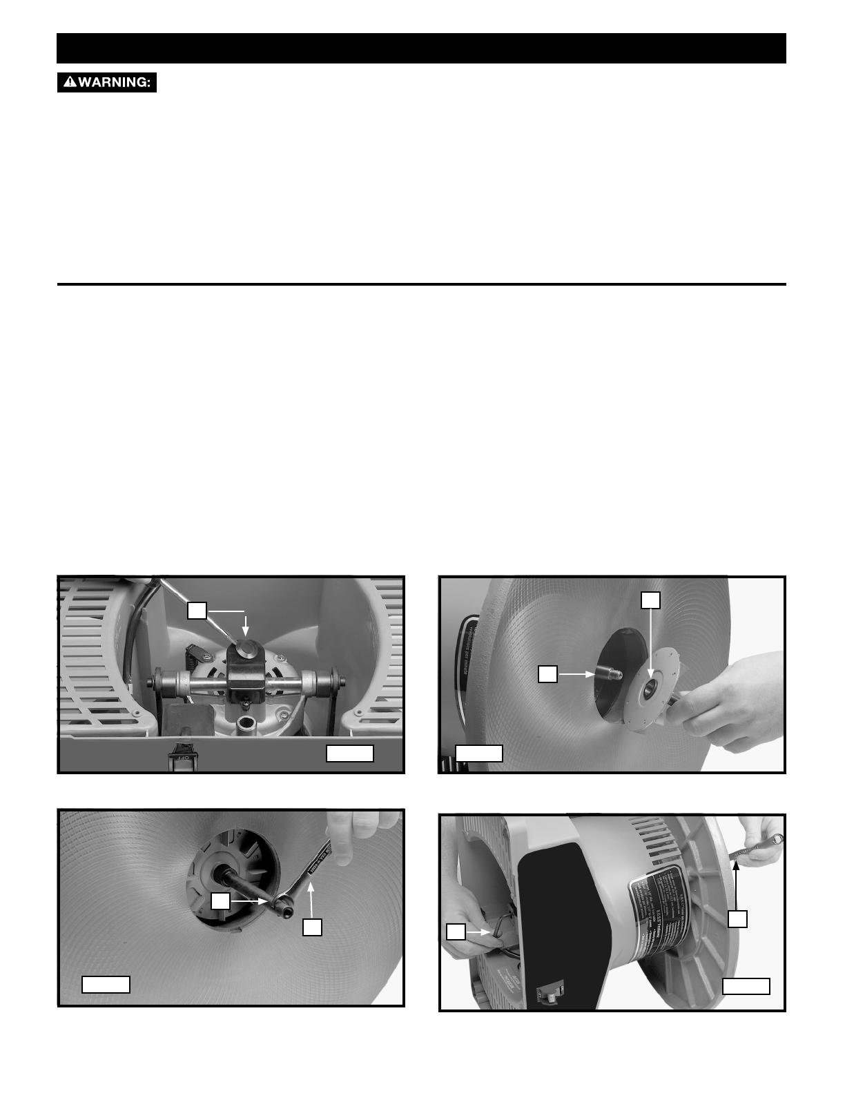
1. Carefully turn the machine upside down. Place it on a clean, rm, supporting surface.
2. Use a at-head screwdriver or similar device to remove the plug (A) Fig. 1 to gain access to socket-head screw (not
shown).
3. Carefully place the machine on its side (Fig. 2). Attach the spindle adapter (B) Fig. 2 to the motor shaft (A) by
turning the spindle adapter counter-clockwise on the shaft.
NOTE: Motor shaft has a left-hand thread.
4. Place a 7/16” open-end wrench (D) Fig. 3 (not sup plied) on the ats of spindle adapter (B). Insert a 3/16” hex
wrench (E) Fig. 3 (supplied) into the socket-head screw located where the plug (A) Fig. 1 was removed in STEP 2.
5. Hold the hex wrench (E) Fig. 4 to prevent the motor shaft from turning. Turn the wrench (D) coun ter -clock wise to
fasten the spindle adapter on the motor shaft.
6. Install the plug (A) Fig. 1 that was removed in STEP 2.
7

FIG. 10
B
E
C
D
A
F
G
FIG. 5
FIG. 7
F
D
G
G
C
H
FIG.8
A
FIG. 9
A
FIG. 11
FIG. 6
C
D
E
ATTACHING THE SANDING DRUM, ABRASIVE SLEEVE AND TABLE INSERT
1. Select the correct abrasive sleeve for your workpiece.
2. Slide that abrasive sleeve (C) Figs. 5 and 6 over the matching sanding drum (D) Figs. 5 and 6. Position this
assembly on the spindle adapter. Place the matching washer (A) Fig. 5 on top of the assembly and fasten it with
a 5/16” screw (E) Fig. 5, using the socket wrench (F) Fig. 7.
NOTE: Turn the screw (E) Fig. 5 counter-clockwise to tighten and clockwise to loosen.
3. Place the table insert (G) Figs. 7 & 8 over the abrasive sleeve (C) and in the cut-out on the table.
NOTE: Arrows on the table insert indicate the top surface.
4. Use the compartments (H) Fig. 8 on the sides of the sander for storing workpieces or accessories.
ATTACHING THE DUST BAG
To attach the dust bag (B) Fig. 10 to the 1-1/2”dust chute (A) Fig. 9, squeeze the spring clamp on the dust bag and
slide it over the dust chute. Release the clamp.
FASTENING THE SANDER TO A SUPPORTING SURFACE
If the machine has any tendency to tip over, slide, or
walk on the supporting surface, you must secure the
machine base to the supporting surface. Use the four
holes, three of which are shown at (A) Fig. 11 to attach
the machine to the supporting surface.
8
OPERATION
OPERATIONAL CONTROLS AND ADJUSTMENTS
A
FIG. 11
FIG. 13
B
A
FIG. 14
B
A
FIG. 15
C
D
E
F
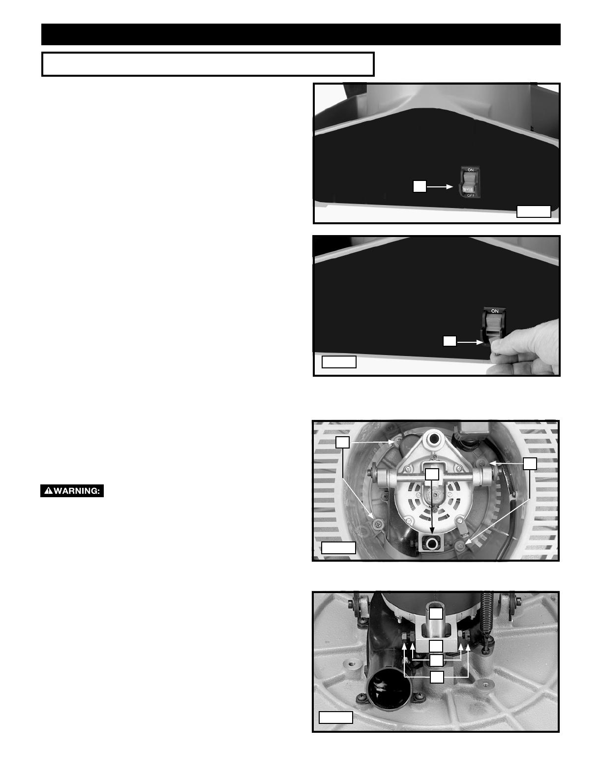
STARTING AND STOPPING THE SANDER
The on/off switch (A) Fig. 12 is located on the sander
base. To turn the sander “ON”, move the switch up to the
“ON” position. To turn the sander “OFF”, move the switch
down to the “OFF” position.
LOCKING THE SWITCH IN THE “OFF” POSITION
IMPORTANT: When the machine is not in use, the
switch should be locked in the “OFF” position to
prevent unauthorized use. To lock the machine, grasp
the switch toggle (B) and pull it out of the switch (Fig. 13).
With the switch toggle (B) removed, the switch will not
operate. However, should the switch toggle be removed
while the sander is running, the machine can be turned
“OFF,” but cannot be restarted without re-inserting the
switch toggle (B).
ADJUSTING THE SPINDLE ASSEMBLY
If excessive play develops in the spindle assembly, or
if noise level increases after extended use, adjust the
spindle assembly.
Disconnect the machine from the
power source!
1. Turn the machine over and place it on a rm supporting
surface.Be careful not to damage the spindle assembly.
2. Remove the four mounting screws (A) Fig. 14. Remove
the case (B) from the machine.
3. IMPORTANT: Position the shaft (C) Fig. 15 inside the
center of the bracket (D). To adjust, loosen the two lock
nuts (E) Fig. 15. Tighten or loos en the two adjusting
screws (F) until the shaft (C) is centered inside the
bracket (D) with the adjustment screws (F) contacting
the shaft. Tighten the two locknuts (E) Fig. 15.
4. Secure the case with the four screws removed in STEP
3.
9
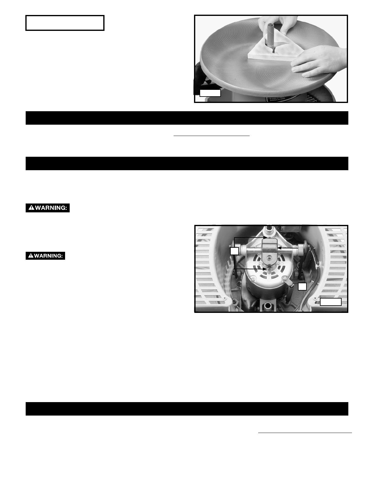
FIG. 16
MACHINE USE
TROUBLESHOOTING
MAINTENANCE
SERVICE
A
B
FIG. 17
Sanding inside curves is illustrated in Fig. 16.
IMPORTANT: Always sand against the rotation of the
sanding drum.
The oscillating action of the sanding drum minimizes
score marks and prevents clogging of the sanding drum,
providing faster, smoother sanding and increasing
the life of the sanding sleeve.
For assistance with your machine, visit our website at www.DeltaMachinery.com for a list of service centers or call the
DELTA Machinery help line at 1-800-223-7278.
KEEP MACHINE CLEAN
Periodically blow out all air passages with dry compressed air. All plastic parts should be cleaned with a soft damp
cloth. NEVER use solvents to clean plastic parts. They could possibly dissolve or otherwise damage the material.
Wear certified safety equipment for eye, hearing and respiratory protection while using compressed air.
After 100 hours of use, Change the grease in the gear
housing.
To gain access to the gear housing:
Disconnect the machine from the
power source!
1. T urn the machine over and loosen the two screws
(A Fig. 17 and remove the cover (B).
2. Remove the old grease and repack the gears
with new grease.
3. Replace the cover.
FAILURE TO START
Should your machine fail to start, check to make sure the prongs on the cord plug are making good contact in the
outlet. Also, check for blown fuses or open circuit breakers in the line.
LUBRICATION & RUST PROTECTION
Apply household oor paste wax to the machine table, extension table or other work surface weekly. Or use a commer-
cially available protective product designed for this purpose. Follow the manufacturer’s instructions for use and safety.
To clean cast iron tables of rust, you will need the following materials: a sheet of medium Scotch-Brite™ Blending
Hand Pad, a can of WD-40® and a can of degreaser. Apply the WD-40 and polish the table surface with the Scotch-
Brite pad. Degrease the table, then apply the protective product as described above.
REPLACEMENT PARTS
Use only identical replacement parts. For a parts list or to order parts, visit our website at www.DeltaMachinery.com/service.
You can also order parts from your nearest factory-owned branch, or by calling our Customer Care Center at 1-800-223-7278
to receive personalized support from highly-trained technicians.
10

ACCESSORIES
Five Year Limited New Product Warranty
DELTA will repair or replace, at its expense and at its option, any new DELTA machine, machine part, or machine accessory which in nor-
mal use has proven to be defective in workmanship or material, provided that the customer returns the product prepaid to a DELTA fac-
tory service center or authorized service station with proof of purchase of the product within five years and provides DELTA with reason-
able opportunity to verify the alleged defect by inspection. For all refurbished DELTA product, the warranty period is 180 days. DELTA will
not be responsible for any asserted defect which has resulted from normal wear, misuse, abuse or repair or alteration made or specifically
authorized by anyone other than an authorized DELTA service facility or representative. Under no circumstances will DELTA be liable for
incidental or consequential damages resulting from defective products. Some states do not allow the exclusion or limitation of incidental
or consequential damages, so the above limitation or exclusion may not apply to you. This warranty is DELTA’s sole warranty and sets
forth the customer’s exclusive remedy, with respect to defective products; all other warranties, express or implied, whether of merchant-
ability, fitness for purpose, or otherwise, are expressly disclaimed by DELTA. For further detail of warranty coverage and warranty repair
information, visit www.DeltaMachinery.com or call 1-800-223-7278. This warranty gives you specific legal rights and you may have other
rights which vary in certain states or provinces.
WARRANTY
TO REDUCE THE RISK
OF INJURY KEEP
HANDS AWAY FROM
MOVING PARTS
PARA REDUCIR EL RIESGO DE
LESIONES MANTENGA LAS
MANOS LEJOS DE LAS
PIEZAS EN MOVIMIENTO
AFIN DE RÉDUIRE LE RISQUE DE
BLESSURES ÉLOIGNER LES MAINS
DES PIÈCES MOBILES
A21636
SERVICE AND REPAIRS
FREE WARNING LABEL REPLACEMENT
If your warning labels become illegible or are missing, call 1-800-223-7278 for a free replacement.
All quality tools will eventually require servicing and/or replacement of parts. For information about DELTA® Power Equipment
Corporation, its factoryowned branches, or an Authorized Warranty Service Center, visit our website at www.DeltaMachinery.
com or call our Customer Care Center at 1-800-223-7278. All repairs made by our service centers are fully guaranteed against
defective material and workmanship. We cannot guarantee repairs made or attempted by others.
You can also write to us for information at DELTA® Power Equipment Corporation, 99 Roush Street, Anderson, South Carolina 29625.
- Attention: Product Service. Be sure to include all of the information shown on the nameplate of your tool (model
number, type, serial number, etc.)
A complete line of accessories is available from your DELTA® Supplier, Factory Service Centers, and DELTA® Authorized
Service Centers. Please visit our Web Site www.DeltaMachinery.com for an online catalog or for the name of your
nearest supplier.
Since accessories other than those offered by DELTA® have not been tested with this product,
use of such accessories could be hazardous. For safest operation, only DELTA® recommended accessories
should be used with this product.
To register your tool for warranty service visit our website at www.DeltaMachinery.com .
11

99 Roush Street
Anderson, South Carolina 29625
(800) 223-7278
www.DeltaMachinery.com
Copyright © 2011 DELTA® Power Equipment Corporation • DPEC000232- 9-29-11
REVISED: 12-08-2014
/