DITEC CROSS 30 Owner's manual

Category
Gate Opener
Type
Owner's manual

This manual is also suitable for

3
CROSS30 - IP1777
FA
FC
130°C
U W V
brown
blue
black
yellow-green
Fig. 4
Fig. 5
130°C
brown
blue
M
3~
Closing limit switch
Opening limit switch
Release switch
black
brown
blue
171412 11 00 0 1 1 2 3 4 6 8 9 20 41
U W V
E1T
black
GB
9
CROSS30 - IP1777
GENERAL SAFETY PRECAUTIONS
This installation manual is intended for professionally
competent personnel only.
Installation, electrical connections and adjustments must be
performed in accordance with Good Working Methods and in
compliance with applicable regulations.
Before installing the product, carefully read the instructions. Bad
installation could be hazardous.
The packaging materials (plastic, polystyrene, etc.) should not
be discarded in the environment or left within reach of children,
as these are a potential source of hazard.
Before installing the product, make sure it is in perfect condi-
tion.
Do not install the product in an explosive environment and atmos-
phere: gas or inammable fumes are a serious hazard risk.
Before installing the motors, make all structural changes relating
to safety clearances and protection or segregation of all areas
where there is risk of being crushed, cut or dragged, and danger
areas in general.
Make sure the existing structure is up to standard in terms of
strength and stability.
The motor manufacturer is not responsible for failure to use
Good Working Methods in building the frames to be motorised
or for any deformation occurring during use.
The safety devices (photocells, safety edges, emergency stops,
etc.) must be installed taking into account: applicable laws and
directives, Good Working Methods, installation premises, sys-
tem operating logic and the forces developed by the motorised
door or gate.
The safety devices must protect any areas where the risk exists
of being crushed, cut or gragged, or where there are any other
risks generated by the motorised door or gate. Apply hazard
area notices required by applicable regulations.
Each installation must clearly show the identication details of
the motorised door or gate.
Before making power connections, make sure the plate
details correspond to those of the power mains.
Fit an omnipolar disconnection switch with a contact opening
gap of at least 3 mm. Make sure an adequate residual current
circuit breaker and overcurrent cutout are tted upstream of the
electrical system.
When necessary, connect the motorised door or gate to a reliable
earth system made in accordance with applicable safety regula-
tions. During installation, maintenance and repair, interrupt the
power supply before opening the lid to access the electrical parts.
To handle electronic parts, wear earthed antistatic conduc-
tive bracelets.
The motor manufacturer declines all responsibility in the event
of component parts being tted that are not compatible with the
safe an correct operation.
For repairs or replacements of products only original spare parts
must be used.
The installer shall provide all information relating to automatic,
manual and emergency operation of the motorised door or gate,
and provide the user with operating instructions.
MACHINERY DIRECTIVE
Pursuant to Machinery Directive (98/37/EC) the installer who
motorises a door or gate has the same obligations as the
manufacturer of machinery and as such must:
- prepare the technical le which must contain the documents
indicated in Annex V of the Machinery Directive; (The
technical le must be kept and placed at the disposal of
competent national authorities for at least ten years from
the date of manufacture of the motorised door);
- draft the EC declaration of conformity in accordance with
Annex II-A of the Machinery Directive and deliver it to the
customer;
- afx the CE marking on the power operated door in accordance
with point 1.7.3 of Annex I of the Machinery Directive.
For more information consult the “Technical Manual Guidelines”
available on Internet at the following address: www.ditec.it
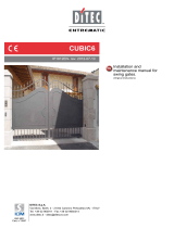
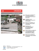
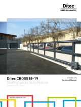
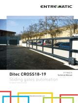
APPLICATIONS
Service class: 5 (minimum 5 years of working life with 600
cycles a day)
Use: HEAVY DUTY (For vehicle or pedestrian accesses to
institutional complexes with very intense use).
- The operating performance specications refer to the re-
commended weight (about 2/3 of maximum allowed weight).
Use with maximum allowed weight could reduce the above
performance specications in tecnhical data.
- The service class, operating times and number of conse-
cutive cycles are merely approximate. These have been
statistically determined in average conditions of use and
are not certain for each single case. They refer to the pe-
riod when the product operates without the need for special
maintenance.
- Each automatic entrance features variable factors such as:
friction, balancing and environmental conditions that can
substantially change both the duration and operating quality
of the automatic entrance or part of its components (including
automatic system). It is up to the installer to adopt adequate
safety coefcients for each single installation.
DECLARATION BY THE MANUFACTURER
(Directive 98/37/EC, Annex II, sub B)
Manufacturer: DITEC S.p.A.
Address: via Mons. Ban, 3
21042 Caronno P.lla (VA) - ITALY
Herewith declares that the electromechanical automatic system
series CROSS30
- is intended to be incorpored into machinery or to be assem-
bled with other machinery to constitute machinery convered
by Directive 98/37/EC;
- is in conformity with the provisions of the following other EC
directives:
Electromagnetic Compatibility Directive 2004/108/EC;
Low Voltage Directive 2006/95/EC;
and furthermore declares that it is not allowed to put the ma-
chinery into service until the machinery into which it is to be
incorporated or of which it is to be a component has been found
and declared to be in conformity with the provisions of Directive
98/37/EC and with national implementing legislation.
Caronno Pertusella, Fermo Bressanini
02-12-2003 (President)
GB
10
CROSS30 - IP1777
1. TECHNICAL DATA
CROSS30E CROSS30
Power supply 400 V~ 50 Hz 400 V~ 50 Hz
Absorption 2,1 A 2,1 A
Motor power 550 W 550 W
Thrust 3000 N 3000 N
Door speed 0,16 m/s 0,16 m/s
Max run 20 m -
Maxdoorweight 3000 kg 3000 kg
Service class 5 - HEAVY DUTY 5 - HEAVY DUTY
Intermittence S3 = 100% S3 = 100%
Temperature -20 °C / +55 °C -20 °C / +55 °C
Degreeofprotection IP45 IP45
Control panel E1T (incorporated) -
2. REFERENCE TO ILLUSTRATIONS
The given operating and performance features can only be
guaranteed with the use of DITEC accessories and safety
devices.
2.1 Standardinstallationreferences(g.1)
[1] Radio
[2] Flashing light
[3] Key selector
[4] Geared motor + control panel
[5] Photocells
[6] Sensitive edge
[7] Opening and closing stop
[8] Connect power supply to an type-approved omnipole
switch with a contact opening gap of no less that 3 mm
(not supplied)
Connection to the grid is made with independent channels
and separated from the connections to the control and
safety devices.
2.2 Gearedmotorreferences(g.3)
[9] Geared motor
[10] Cable tting
[11] Housing
[12] Terminal board
[13] Release screw
[14] Pinion module 6
[15] Magnetic limit switch
[16] Base plate
[17] Limit switch bracket
[18] Limit switch of release access door
3. INSTALLATION
Unless otherwise specied, all measurements are expressed
in millimetres (mm).
3.1 Preliminary checks
Check the stability of the wing (derailing and lateral falls) and
the sliding wheels and that the upper guides do not cause any
friction.
The sliding track must be securely anchored to the ground and
fully exposed along its full length.
It must be perfectly smooth so as to avoid jamming of the gate.
Provide opening and closing stops.
Note: make sure that the gate can not exit the sliding guides
and fall.
If the gate has slits, make sure they are covered to prevent
shearing points.
Safety device should be installed at the end of the wing to reduce
the collision force.
3.2 Base plate position
- Insert the anchor ties onto the base plate [16] and x them
with the supplied nuts.
- Lay a concrete foundation with buried anchoring brackets
and the base plate, making sure that it is pefectly level and
smooth, complying with the measurements shown in gure
(the side to be placed in contact with the ground is marked
on the base plate). If a concrete foundation is already
available, secure the motor by means of appropriate
dowels (not supplied) capable of withstanding a pushing
force of at least 3000 N.
Warning: the base plate is smaller than the gear motor
base. Check the base plate sides are free [*].
GB
11
CROSS30 - IP1777
3.3 Geared motor installation
- Open the gear motor removable cover. Loosen the three
screws [A] (the upper screw must not be completely
loosened) and remove the case.
- Remove the nuts used to fasten the anchoring brackets.
- Position the gearmotor onto the base plate.
- Gearmotor adjustments
Horizontally, by having it slide along the gear motor base
slot (approx. 20 mm).
Vertically, by means of the 4 level screws [B] and by insert-
ing the provided shims [C].
Note: once the level shims have been inserted [C], loosen
the screws[B], the motor shall weigh only on the shims [C].
Note: while adjusting vertically, keep the motor slightly
raised above the base plate so as to allow enough space to
secure the rack and to make any subsequent adjustments,
if necessary.
3.4 Rack installation
Warning: use a module 6 rack.
- Release the gearmotor and set the gate in the open po-
sition. Place the rack on pinion [14] and move the gate
manually to secure the rack along its full length.
- Once the rack has been secured, vertically adjust the
geared motor so as to have a gap of 2 to 3 mm between
the pinion and the rack with screws [B].
Warning: the motor shall weigh only on the shims [C].
- Firmly secure the gearmotor with the nuts [D].
- Slightly lubricate the rack and pinion after assembly.
Manually check that the gate slides evenly and without
friction.
min
90
200
80
OPENING
X+20
65*
65*11654230
400
Ø80 Ø12
TCEI-M8x16 TCEI-M8x16
A A
A
TC-M8x20
B
B
B
D
D
D
C
C
D
min
90
200
80
OPENING
X+20
65*
65*11654230
400
Ø80 Ø12
max
160
17 17
18
2÷3
GB
12
CROSS30 - IP1777
3.5 Limit switch adjustment
- Manually position the door wing completely open and
fasten the limit switch brackets [17] onto the rack so that
the lever limit switch exceeds the bracket’s length by
approximately 2/3. Repeat the operation with door wing
completely closed.
- Provide power and carry out some opening and closing
operations (see the starting instructions in the control panel
installation manual).
Adjust the limit switch bracket [17] so that the gate stops
approximately 20 mm before the opening and closing
stops.
4. ELECTRICAL CONNECTIONS
The electrical connections and starting are illustrated in the
installation manual of the E1T control panel.
Note: (Only for CROSS30) connect the motor and the mechani-
cal stops to the E1T electronic panel (g. 5).
Warning: connect the yellow-green ground cable to the clamp
already connected to the motor, as it is shown in the gure.
1717
15÷20
4.1 Openingtotheright
The automation is provided with opening to the right (automation
side view).
- Bring the gate to a central position and give an opening
command (1-3), check the motor opens to the right, other-
wise reverse two phases of the 400 V~ power supply.
4.2 Openingtotheleft
- Reverse the connection of the limit switch terminals on the
control panel: 11→12, 12→11.
- Bring the gate to a central position and give an opening
command (1-3), check the motor opens to the left, other-
wise reverse two phases of the 400 V~ power supply.
5. MAINTENANCEPROGRAM(every6months)
Disconnect the power supply and release the gearmotor (see
RELEASE/BLOCK operations):
- Visually check that the gate, the xing brackets and existing
structure have suitable mechanical strength and are in
good condition.
- Check the gate-gearmotor alignment, the distance (2-3
mm) between the throat of the pinion and the crest of the
rack.
- Clean the wheel’s sliding guide, the rack and pinion of the
gear motor and slightly lubricate the rack and pinion of the
gearmotor. Manually check that the gate slides evenly and
without friction.
Connect the power supply and block the gearmotor (see RELE-
ASE/BLOCK operations):
- Check that the limit switches are working correctly (the
gate should stop 20 mm before the stop).
- Check the power adjustment.
- Check that all control and safety functions are working
correctly.
ATTENTION: For spare parts, see the spares price list.
OPENING
~20
yellow-green
Allrightreserved
All data and specications have been drawn up and checked with the greatest care. The manufacturer cannot however take any
responsibility for eventual errors, ommisions or incomplete data due to technical or illustrative purposes.
OPERATING INSTRUCTIONS FOR FOR SLIDING GATES AUTOMATION CROSS30
RELEASE INSTRUCTIONS
In case of fault or power failure, insert the key and turn it
clockwise. Open the removable cover and unlock the pinion
gear by turning the pinion gear pin counterclockwise by means
of the provided tool.
This allows to push the gate manually.
Attention: perform locking and lock release operations
with motor cut off.
WARNING: Opening the removable cover or removing the gear
motor case, means the limit switch is opened, thus preventing
operations.
LOCK INSTRUCTION
To relock the geared motor, rotate the pinion clockwise, strongly
tighten, and re-close the door.
GENERAL SAFETY PRECAUTIONS
The following precautions are an integral and essential part
of the product and must be supplied to the user.
Read them carefully as they contain important indications for
the safe installation, use and maintenace.
These instruction must be kept and forwarded to all possible
future user of the system.
This product must be used only for that which it has been ex-
pressely designed.
Any other use is to be considered improper and therefore dangerous.
The manufacturer cannot be held responsible for possible da-
mage caused by improper, erroneous or unresonable use.
Avoid operating in the proximity of the hinges or moving me-
chanical parts.
Do not enter the eld of action of the motorised door or gate
while in motion.
Do not obstruct the motion of the motorised door or gate as this
may cause a situation of danger.
Do not lean against or hang on to the barrier when it is moving.
Do not allow children to play or stay within the eld of action of
the motorised door or gate.
Keep remote control or any other control devices out of the reach
of children, in order to avoid possible involuntary activation of
the motorised door or gate.
In case of breack down or malfunctioning of the product, discon-
nect from mains, do not attempt to repair or intervene directly
and contact only qualied personnel.
Failure to comply with the above may create a situation of
danger.
All cleaning, maintenance or repair work must be carried out by
qualied personnel.
In order to guarantee that the system works efciently and
correctly it is indispensable to comply with the manufacturer’s
indications thus having the periodic maintenance of the motori-
sed door or gate carried out by qualied personnel.
In particular regular checks are recommended in order to verify
that the safety devices are operating correctly. All installation,
maintenance and repair work must be documented and made
available to the user.
Installer:
ON
OFF
DITEC S.p.A.
Via Mons. Ban, 3
21042 Caronno Pertusella (VA) - ITALY
Tel. +39 02 963911 - Fax +39 02 9650314
www.ditec.it - [email protected]
TEAR OFF AND DELIVER TO USER
Quartod’Altino(VE) CaronnoPertusella(VA)
Lokeren Oberursel
Palaiseau Balerna
Orlando
DITEC S.p.A.
Via Mons. Ban, 3
21042 Caronno P.lla (VA)
ITALY
Tel. +39 02 963911
Fax +39 02 9650314
www.ditec.it
DITEC BELGIUM
LOKEREN
Tel. +32 9 3560051
Fax +32 9 3560052
www.ditecbelgium.be
DITEC DEUTSCHLAND
OBERURSEL
Tel. +49 6171 914150
Fax +49 6171 9141555
www.ditec-germany.de
DITEC ESPAÑOLA
ARENYS DE MAR
Tel. +34 937958399
Fax +34 937959026
www.ditecespanola.com
DITEC FRANCE
PALAISEAU
Tel. +33 1 64532860
Fax +33 1 64532861
www.ditecfrance.com
DITEC GOLD PORTA
ERMESINDE
Tel. +22 977 35 20
Fax +22 977 35 28
www.goldporta.com
DITEC SVIZZERA
BALERNA
Tel. +41 91 6463339
Fax +41 91 6466127
www.ditecswiss.ch
DITEC AMERICA
ORLANDO - FLORIDA - U.S.A.
Tel. +1 407 8880699
Fax +1 407 8882237
www.ditecamerica.com
DITEC CHINA
SHANGHAI
Tel. +86 21 62363861
Fax +86 21 62363863
www.ditec.cn
DITEC TURCHIA
ISTANBUL
Tel. +90 21 28757850
Fax +90 21 28757798
  • Page 1 1
  • Page 2 2
  • Page 3 3
  • Page 4 4
  • Page 5 5
  • Page 6 6
  • Page 7 7
  • Page 8 8
  • Page 9 9
  • Page 10 10
  • Page 11 11
  • Page 12 12
  • Page 13 13
  • Page 14 14
  • Page 15 15
  • Page 16 16
  • Page 17 17
  • Page 18 18
  • Page 19 19
  • Page 20 20
  • Page 21 21
  • Page 22 22
  • Page 23 23
  • Page 24 24
  • Page 25 25
  • Page 26 26
  • Page 27 27
  • Page 28 28
  • Page 29 29
  • Page 30 30
  • Page 31 31
  • Page 32 32
  • Page 33 33
  • Page 34 34

DITEC CROSS 30 Owner's manual

Category
Gate Opener
Type
Owner's manual
This manual is also suitable for

Ask a question and I''ll find the answer in the document

Finding information in a document is now easier with AI