
10GbE Pass-Thru Module
User Guide
Part Number 573130-002
December 2010 (Second Edition)

© Copyright 2009, 2010 Hewlett-Packard Development Company, L.P.
The information contained herein is subject to change without notice. The only warranties for HP products and services are set forth in the express
warranty statements accompanying such products and services. Nothing herein should be construed as constituting an additional warranty. HP
shall not be liable for technical or editorial errors or omissions contained herein.
Microsoft and Windows are U.S. registered trademarks of Microsoft Corporation. Bluetooth is a trademark owned by its proprietor and used by
Hewlett-Packard Company under license.
Intended audience
This document is for the person who installs, administers, and troubleshoots HP BladeSystem c-Class
products. Only persons experienced in server blade technology and configuration should attempt these
procedures. HP assumes you are qualified in the servicing of computer equipment and trained in
recognizing hazards in products with hazardous energy levels.

Contents 3
Contents
Introduction .................................................................................................................................. 5
Features ................................................................................................................................................... 5
Enterprise class performance ............................................................................................................. 5
Configuration and management ........................................................................................................ 5
Diagnostic tools ............................................................................................................................... 5
Pass-thru module architecture ...................................................................................................................... 5
Port mapping .................................................................................................................................. 6
Dual pass-thru modules ..................................................................................................................... 6
Redundant paths to server bays ......................................................................................................... 6
XModem .................................................................................................................................................. 6
Component identification ............................................................................................................... 7
10GbE Pass-Thru Module front panel ........................................................................................................... 7
Installing the pass-thru module ........................................................................................................ 9
Manually configuring the pass-thru module ................................................................................................... 9
Module security ............................................................................................................................... 9
Installing the module .................................................................................................................................. 9
Accessing the pass-thru module CLI ............................................................................................................ 10
Accessing the pass-thru module CLI remotely ..................................................................................... 10
Accessing the pass-thru module CLI locally ........................................................................................ 11
Production mode CLI ...................................................................................................................... 11
CLI menu ...................................................................................................................................... 11
Installing SFP+ transceivers ....................................................................................................................... 12
Replacing a pass-thru module ....................................................................................................... 13
Replacing an existing module ................................................................................................................... 13
Updating the 10GbE pass-thru firmware ........................................................................................ 14
Methods for updating the 10GbE Pass-Thru Module firmware ....................................................................... 14
Updating the firmware image using the Onboard Administrator CLI ............................................................... 14
Updating the firmware image using a USB key and the Onboard Administrator CLI ......................................... 17
Updating the 10GbE Pass-Thru Module firmware using the pass-thru serial port ............................................... 18
Performing a serial firmware image download .................................................................................. 18
Updating the firmware image using the serial port ............................................................................. 18
For more information ................................................................................................................... 20
Additional references ............................................................................................................................... 20
Troubleshooting .......................................................................................................................... 21
Health LED on the pass-thru module is not on .............................................................................................. 21
Health LED on the pass-thru module stays amber for more than 30 seconds and pass-thru module does not boot . 21
No link LED appears, even after you plug the cable into the SFP+ module ...................................................... 21
Cannot access the pass-thru module serial console interface using an RS232 connection from a PC Terminal
Emulation Program .................................................................................................................................. 22
Error message appears on the serial console screen that the pass-thru module failed to complete the system self-test
............................................................................................................................................................. 22
The keyboard locks up when you use HyperTerminal to log in to the pass-thru module through the console interface
............................................................................................................................................................. 22

Contents 4
Cannot connect to the pass-thru module console interface remotely using Onboard Administrator ...................... 22
The download fails after starting to download the firmware file ..................................................................... 23
The pass-thru module configuration is corrupt .............................................................................................. 23
SFP+ transceiver port is disabled ............................................................................................................... 23
Technical specifications ............................................................................................................... 24
General specifications ............................................................................................................................. 24
Port names ............................................................................................................................................. 24
Physical and environmental specifications ................................................................................................... 25
Mini-USB to DB-9 serial adapter pin assignment .......................................................................................... 25
Regulatory compliance notices ..................................................................................................... 27
Class A equipment .................................................................................................................................. 27
Modifications .......................................................................................................................................... 27
Cables ................................................................................................................................................... 27
Canadian notice ..................................................................................................................................... 27
European Union regulatory notice ............................................................................................................. 27
Japanese class A notice ........................................................................................................................... 28
Korean class A notice .............................................................................................................................. 28
Laser compliance .................................................................................................................................... 28
Electrostatic discharge ................................................................................................................. 30
Preventing electrostatic discharge .............................................................................................................. 30
Grounding methods to prevent electrostatic discharge .................................................................................. 30
Acronyms and abbreviations ........................................................................................................ 31
Index ......................................................................................................................................... 33

Introduction 5
Introduction
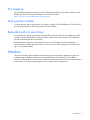
Features
The 10GbE Pass-Thru Module is designed for easy installation and high performance in an environment
where network traffic and users increase continually.
Enterprise class performance
The 10GbE Pass-Thru Module includes the following features:
• The unique ability to provide both 1 Gigabit and 10 Gigabit functionality on each port, enabling
greater network flexibility
• Full support on the HP c-Class BladeSystem server blade enclosure and infrastructure compatible with
any combination of HP c-Class BladeSystem server blades
• The ability to replace an existing 10GbE Pass-Thru Module without powering down the server blades
or the enclosure
• Preconfiguration for immediate use with the HP c-Class BladeSystem Enclosure
• Robust configuration and management from the 10GbE Pass-Thru Module internal or external CLI
• Support for 10GbE Pass-Thru Module firmware upgrade using XModem functionality
Configuration and management
The 10GbE Pass-Thru Module has the ability to enable or disable auto-negotiation on any port.
Diagnostic tools
The 10GbE Pass-Thru Module includes the following hardware and firmware diagnostic tools:
• POST built into the pass-thru module boot process
• Pass-thru module LED panel displaying per port status and speed
• Health and UID status LEDs
• Reset switch and mini-USB to DB-9 RS232 management serial port (mini-USB to DB-9 RS232 cable
sold separately)
• The ability to return the pass-thru module to known good condition in case of firmware corruption
Pass-thru module architecture
The pass-thru module provides a 10GBASE-KR-to-SFI interface conversion, connecting through the
enclosure backplane to 10GBASE-KR lanes from 16 server blades and brings out Small Form Factor
Interface signals terminating in SFP/SFP+ transceiver connectors on the faceplate of the module.

Introduction 6
Port mapping
For detailed port mapping information, see the HP BladeSystem Enclosure Quick Setup Guide or the HP
BladeSystem Enclosure Setup and Installation Guide on the HP website
(http://www.hp.com/go/bladesystem/documentation).
Dual pass-thru modules
In a dual pass-thru module configuration, two pass-thru modules in the HP BladeSystem c7000 Enclosure
provide redundant paths to the network ports on the server blades.
Redundant paths to server bays
In a dual pass-thru module configuration, redundant Ethernet signals from each server blade are routed
through the enclosure backplane to separate pass-thru modules within the enclosure. This configuration
provides redundant paths to each server bay.
Redundant Ethernet signals from each blade server are routed through the enclosure backplane to
separate pass-thru modules within the enclosure. However, port to server mapping varies based on the
type of server blade installed.
XModem
The pass-thru module supports XModem for transferring files during firmware upgrade using the serial
management port. XModem sends blocks of data and includes an error-detection system called a
checksum. When the data is received, the error detection system ensures that the entire message reached
its destination. If not, the receiving computer sends a request for data retransmission.

Component identification 7
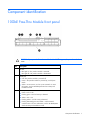
Component identification
10GbE Pass-Thru Module front panel
CAUTION: If you press the Reset button while the Health LED is green, the pass-thru module
resets.
Item Description
1 UID LED
•
Blue light on—The pass-thru module is activated.
•
Blue light off—The pass-thru module is deactivated.
2 Health LED
•
Off—The pass-thru module is powered off.
•
Green—The pass-thru module is powered up, and all ports
match.
•
Amber—An issue exists, such as a port mismatch. For more
information, see the HP BladeSystem Enclosure Setup and
Installation Guide.
3 Ethernet port
•
Green—Link is 10G.
•
Flashing green—10G link activity is detected.
•
Amber—Link is 1G.
•
Flashing amber—1G link activity is detected.
•
Flashing alternately green and amber—A link mismatch
condition exists. For more information, see the HP BladeSystem
Enclosure Setup and Installation Guide.

Component identification 8
Item Description
4 Reset button
5 Mini-USB RS232 management serial port
6 Ports 1-16
SFP+ ports to support SFP and SFP+ transceiver modules and Direct
Attach Cables (DAC).

Installing the pass-thru module 9
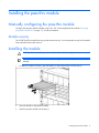
Installing the pass-thru module
Manually configuring the pass-thru module
Configure the pass-thru module manually using a CLI. See "Accessing the pass-thru module ("Accessing
the pass-thru module CLI" on page 10)" for more information.
Module security
The 10GbE Pass-Thru Module does not provide network security. You must provide security for the module
from somewhere else on the network.
Installing the module
CAUTION: Do not attach the pass-thru module cables until after configuration.
IMPORTANT: Make sure that the server NIC configuration matches the pass-thru module bay
selected.
1. If a blank is installed in the bay, open the handle (1) and pull the blank out of the bay (2).
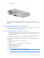
2. Open the handle on the pass-thru module.
3. Insert the pass-thru module into the bay (1).

Installing the pass-thru module 10
4.
Close the handle (2).
Complete installation is indicated by a green Health LED. If the Health LED is amber or power is not
applied to the module, see the HP BladeSystem Enclosure Setup and Installation Guide for troubleshooting
information.
Accessing the pass-thru module CLI
You can access the pass-thru module CLI remotely using the Onboard Administrator enclosure or locally
using the mini-USB to DB-9 RS232 Management serial port.
Accessing the pass-thru module CLI remotely
1. Access the Onboard Administrator command line using telnet, SSH, or a serial connection. For more
information on how to access the Onboard Administrator CLI, see the HP BladeSystem Onboard
Administrator User Guide.
2. Use the connect interconnect <bay> command to access the module. For example, if the
module is located in bay 2, enter the connect interconnect 2 command.
To properly connect to the pass-thru module, you must disable flow control in the Onboard Administrator
connect console.
To disable flow control after you have connected to the module:
1. Press Enter.
2. Press Ctrl + _ (Ctrl + Shift + underscore) to access the Connect Utility menu.
3. Enter C to change the port settings.
4. Enter R to change settings for the remote port.
5. Enter N to disable flow control.
After you have exited the menu, the pass-thru module CLI appears.
NOTE: If the pass-thru module CLI does not appear, press Enter.

Installing the pass-thru module 11
Accessing the pass-thru module CLI locally
1. Using a null-modem mini-USB to DB-9 RS232 serial cable (not included), connect the pass-thru
module management port to a local client device (such as a laptop computer).
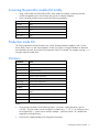
2. Open a terminal emulation session and set the following parameters:
Parameter Value
Baud rate 9600
Data bits 8
Parity None
Stop bits 1
Flow control None
Production mode CLI
The CLI provides backward and forward cursor control, backward deletion capability, and a 16-line
history buffer. There is no tab "auto-completion" feature, but if there is enough information to determine
the command to be used, the interface will accept part of the CLI command. For example, entering sys is
enough to enter the system menu.
CLI menu
Command Result
Main menu
system Displays System menu.
port Displays Port menu.
System menu
info Displays system information.
config Enables you to set active or factory default configuration.
dumpconfig Dumps active configuration.
reset Resets pass-thru module.
Port menu
auto Displays Port menu auto-negotiation configuration
details.
info Displays port information.
Global command
save Saves configuration.
Notes:
• The port/auto command uses the following format: "/port/auto <uplink|downlink> <port #>
<on/off>". The port number can be a sequence of numbers (e.g., "1 3 5 15") or, if all ports are to
be configured, the "*" option can be used (for example, "/port/auto uplink * off" disables auto-
negotiation on all uplink ports).
• The port/info command displays link configuration and status.

Installing the pass-thru module 12
• The system/info command displays image version, board revision, or chip revisions.
• The effect from any CLI command is immediate. For example, configuring auto-negotiation on a port
takes effect when the command is completed.
• Flow control is not configurable because the pass-thru module cannot handle or generate pause
packets. When using the 10GbE Pass-Thru Module, you must ensure that your pause configuration is
correct for both link partners.
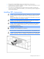
Installing SFP+ transceivers
CAUTION: Disconnect all cables before removing or installing an SFP+ transceiver, because of
the potential damage to the cables, the cable connector, or the optical interfaces in the SFP+
transceiver.
Removing and installing an SFP+ transceiver can shorten the life of the product. Do not remove
and insert SFP+ transceivers more often than is necessary.
CAUTION: HP recommends attaching an ESD-preventative wrist strap to your wrist and to a
bare metal surface on the chassis to prevent electrostatic discharge.
CAUTION: When not using the fiber-optic SFP+ transceiver and cable, be sure to install the
dust plugs on both. The plugs and caps protect the SFP+ transceiver ports and cables from
contamination and ambient light.
1. Remove the dust plug and save for future use.
IMPORTANT: Use only HP-approved SFP+ transceivers.
2. Insert the SFP+ transceiver. With latch closed, be sure that the transceiver is fully seated and secure.
CAUTION: If you plan to install the SFP+ transceiver into the bottom row of the module, before
installation, rotate the SFP+ transceiver 180 degrees from the position shown in the illustration.

Replacing a pass-thru module 13
Replacing a pass-thru module
Replacing an existing module
CAUTION: Removing the pass-thru module from a powered enclosure results in the loss of
network communications between the server blade network ports and the network
infrastructure.
For continued blade-server network communication and services availability before removing
the module, redirect critical high-availability services or applications to use the redundant
network ports.
CAUTION: Do not connect the pass-thru module until after configuration.
1. Remove and label the cables.
2. Remove the module.
3. Slide the new module fully into the interconnect bay. For more installation information, see "Installing
the module (on page 9)."
4. Close the ejector lever and wait for the module to boot completely.

Updating the 10GbE pass-thru firmware 14
Updating the 10GbE pass-thru firmware
Methods for updating the 10GbE Pass-Thru Module
firmware
CAUTION: The pass-thru module automatically reboots after the firmware update, which
disrupts all server traffic on all ports on this pass-thru module. The server blades can be
powered on while this pass-thru module firmware is updated, but they lose connectivity while
the firmware reboots on each pass-thru module.
CAUTION: Do not power off the pass-thru module during the download process. Doing so will
require you to power cycle the pass-thru module. Power cycling requires a successful image
download before the pass-thru module is operable.
The 10GbE Pass-Thru Module firmware can be updated using the following methods:
• Onboard Administrator CLI
o Remotely through the management network
o Locally using a PC connected to the Onboard Administrator DB9 serial port
o Locally through a VGA and keyboard connected to the Onboard Administrator Enclosure KVM
CLI console, if you are using an HP BladeSystem c7000 Onboard Administrator with KVM or the
c3000 KVM option
NOTE: When using the Onboard Administrator for the firmware update, the pass-thru module
firmware image must be available on an HTTP, FTP, or TFTP file, or located on a USB key drive
accessible by the active Onboard Administrator.
• Locally using a PC connected to the pass-thru serial connector
NOTE: If you are using a local PC to update the firmware, the pass-thru module firmware
image must be accessible from that PC.
NOTE: The pass-thru module boot code firmware image is usually named 10GPTHRU-
w.x.y.z_FW.bin
, where w.x.y.z is the firmware version number.
Updating the firmware image using the Onboard
Administrator CLI
NOTE: The firmware update uses the Onboard Administrator Xmodem support with a firmware
file hosted on an HTTP, FTP, or TFTP server. The firmware transfer can take up to seven minutes
to complete.

Updating the 10GbE pass-thru firmware 15
NOTE: If you are using a USB key to transfer the firmware file, see "Updating the firmware
image using a USB key and the Onboard Administrator CLI (on page 17)" for steps that must
be completed before beginning this procedure.
1. Access the Onboard Administrator CLI remotely using Telnet or SSH, or locally using a serial
connection to the active Onboard Administrator DB9 serial connector, or VGA and keyboard
connected to the enclosure KVM ports. For more information on how to access the Onboard
Administrator CLI, see the HP BladeSystem Onboard Administrator User Guide.
2. Log in to the active Onboard Administrator with a valid username and password that has a role on
the Onboard Administrator allowing access to the pass-thru interconnect module.
NOTE: The pass-thru module in the examples below is located in interconnect bay 2.
Wherever the 2 appears, substitute the number of the interconnect bay your pass-thru module
is installed into.
3. At the Onboard Administrator prompt, enter connect interconnect 2. The following message
appears:
NOTICE: This pass-thru connection to the integrated I/O console
is provided for convenience and does not supply additional access
control. For security reasons, use the password features of the
integrated switch.
Connecting to integrated switch 2 at 9600,N81...
Escape character is '<Ctrl>_' (Control + Shift + Underscore)
4. To display the pass-thru module console, press Enter.
5. Press Ctrl + Shift + _. The following message appears:
Command: D)isconnect, C)hange settings, send B)reak, E)xit command mode
X)modem send >
6. Enter C. The following message appears:
Change settings for: L)ocal Session, R)emote Port [I/O Bay 2], E)xit
7. Enter R. The following message appears:
Settings: B)audrate; flow control: N)one H)ardware S)oftware; E)xit >
8. Enter N. The following message appears:
Connected to integrated switch 2 at 9600,N81.
Escape character is '<Ctrl>_' (Control + Shift + Underscore)
9. At the 10GbE Pass-Thru # prompt, enter /system. The following message appears:
[System Menu]
info - System Information Display
config - Set Active or Factory Default Config
dumpconfig - Dump Saved Config
xmodem - Download new image using XMODEM
reset - Reset The Switch
10. At the System# prompt, enter xmodem. The following message appears:
Confirm reset and start XMODEM download mode [y/n]:
11. Enter y. The following message appears:
System Reset ...
Ready to begin XMODEM file transfer. Hit return to continue.

Updating the 10GbE pass-thru firmware 16
12.
Press the Enter key. The module console begins to print C characters until the Xmodem transfer
begins.
13. Press Ctrl + Shift + _. The following message appears:
Command: D)isconnect, C)hange settings, send B)reak, E)xit command mode
X)modem send >
14. Enter x. The following message appears:
Xmodem Send: Send a file to the interconnect module using the xmodem
transfer protocol. The file can be downloaded to the OA from an HTTP(S),
FTP, or TFTP server. After the file has been downloaded, the OA will
transfer it to the switch. Please enter the URL below.
15. Enter the transfer URL (tftp://tftpServerIPAddress/10GPTHRU-1.0.7.0_FW.bin). The following
message appears:
Downloading file ... successful (transferred 210216 bytes)
Continue with transfer (yes/no)?
16. Enter y. The following message appears:
Starting transfer. Press '<Ctrl>_' (Control + Shift + Underscore) to
cancel.
Note: The transfer will terminate after 30 seconds of inactivity.
……….
The pass-thru module displays multiple lines of . characters until the entire firmware transfer is
complete. The following message appears:
Transfer complete.
Welcome to the HP 10GbE Pass-Thru Module
Running image 1.0.7.0
Initializing ports................................
[10Gb Pass-Thru Menu]
system - System Menu
port - Port Menu
global - Global Commands Menu
10Gb Pass-Thru# Port 1 is ENABLED
Port 2 is ENABLED
Port 3 is ENABLED
Port 5 is ENABLED
Port 6 is ENABLED
Port 7 is ENABLED
Port 8 is ENABLED
Port 9 is ENABLED
Port 10 is ENABLED
Port 11 is ENABLED
Port 12 is ENABLED

Updating the 10GbE pass-thru firmware 17
Port 13 is ENABLED
Port 14 is ENABLED
Port 15 is ENABLED
Port 16 is ENABLED
Port 1 Installed CU SFP
Port 1 Approved CU SFP
NOTE: If the module console displays C characters instead of . characters, return to step 14 to
restart the Xmodem transfer.
17. Press Ctrl + Shift + _. The following message appears:
Command: D)isconnect, C)hange settings, send B)reak, E)xit command mode
X)modem send >
18. Enter d.
19. To update the firmware on any other pass-thru modules installed in this enclosure, begin at step 4.
Updating the firmware image using a USB key and
the Onboard Administrator CLI
NOTE: The firmware update uses the Onboard Administrator Xmodem support with a firmware
file hosted on an HTTP, FTP, or TFTP server. The firmware transfer can take up to seven minutes
to complete.
If no HTTP, FTP, or TFTP server is available, you can download the pass-thru module firmware file to a
USB key which can then be inserted into the active Onboard Administrator USB port.
To update the image:
1. Copy the pass-thru module firmware file to the FAT32 formatted USB key in the \ directory.
2. Create a text file named text.cfg containing the following line:
hello
3. Copy the text.cfg file to the USB key in the \ directory.
4. Insert the USB key into the active Onboard Administrator USB port.
5. Log in to the active Onboard Administrator CLI.
6. At the Onboard Administrator prompt, enter show usbkey. The following message appears:
Configuration Script Files
---------------------------------------
usb://d1/test.cfg
7. At the Onboard Administrator prompt, enter show oa network. The following message appears:
Onboard Administrator #1 Network Information:
Name: marketing3
DHCP: Disabled
IP Address: 16.83.88.66
Netmask: 255.255.252.0
Gateway Address: 16.83.88.1
Primary DNS: 16.110.135.51

Updating the 10GbE pass-thru firmware 18
Secondary DNS: 16.110.135.52
MAC Address: F4:CE:46:86:FA:5D
Link Settings: Auto-Negotiation, 100 Mbit, Full Duplex
Link Status: Active
Enclosure IP Mode: Disabled
8. To begin the firmware upgrade, begin at step 3 of "Updating the firmware image using the
Onboard Administrator CLI (on page 14)" and continue following the instructions.
The pass-thru module firmware is available as a URL
(http://OA_IP_Address/media/usbkey/d1/filename) at the active Onboard Administrator IP
address with a path based on the d# command in the show usbkey response. In the URL, substitute
the following:
o Replace OA_IP_Address with the actual Onboard Administrator IP address
o Replace d1 with the actual d#
o Replace filename with the pass-thru filename
Then, substitute the new URL in step 15.
Updating the 10GbE Pass-Thru Module firmware
using the pass-thru serial port
NOTE: Downloading firmware through the pass-thru serial port is not the preferred method for
upgrading a firmware image.
Performing a serial firmware image download
If you are upgrading a pass-thru module directly from any existing operating system or boot code image,
perform a serial download of the pass-thru module operating system firmware or boot code firmware.
This procedure requires:
• A computer running terminal emulation software
• 10GbE Pass-Thru Module operating system firmware or boot code images
Updating the firmware image using the serial port
CAUTION: The pass-thru module automatically reboots after the firmware update, which
disrupts all server traffic on all ports on this pass-thru module. The server blades can be
powered on while this pass-thru module firmware is updated, but they lose connectivity while
the firmware reboots on each pass-thru module.
CAUTION: Do not power off the pass-thru module during the download process. Doing so will
require you to power cycle the pass-thru module. Power cycling requires a successful image
download before the pass-thru module is operable.

Updating the 10GbE pass-thru firmware 19
NOTE: The pass-thru module boot code firmware image is usually named 10GPTHRU-
w.x.y.z_FW.bin, where w.x.y.z is the firmware version number.
1. Using the null modem mini-USB to DB-9 cable, connect the console port of the pass-thru module to
the serial port of a computer that supports XModem/1K XModem.
2. Start HyperTerminal (part of Microsoft® Windows® operating system) or equivalent terminal
emulation application (depending on the operating system), and set the parameters for terminal
emulation console:
Parameter Value
Baud rate 9600
Data bits 8
Parity None
Stop bits 1
Flow control None
3. Power on or reboot the pass-thru module.
4. Hold down the Shift key and press the B key repeatedly during boot up, until the following message
appears: "Ready to begin XMODEM file transfer. Press Enter to continue."
5. Repeatedly press the Enter key on the computer that is connected to the console port of the pass-thru
module. When the console port is successfully communicating with the computer, indicating
readiness for image transfer, continuous Cs appear.
6. Be sure that the new pass-thru module boot code firmware file is available on the computer. This file
can be downloaded from the HP website (http://www.hp.com/go/bladesystem/documentation).
7. Select <Transfer-Send File> from the menu, and choose the following options in the Send File
window:
Filename: C:\#*!<unassigned_variable!*#
Protocol: 1K XMODEM
The Send File window displays the progress of the file transfer. The file transfer might take up to 7
minutes.
NOTE: Although slower, XModem also works if 1K XModem is not used.
After completing the transfer, the new image automatically boots.

For more information 20
For more information
Additional references
Configure the 10GbE Pass-Thru Module after installation. Detailed information about how to configure the
pass-thru module is available in 10GbE Pass-Thru Module Installation Instructions for HP BladeSystem c-
Class Enclosures.
Page is loading ...
Page is loading ...
Page is loading ...
Page is loading ...
Page is loading ...
Page is loading ...
Page is loading ...
Page is loading ...
Page is loading ...
Page is loading ...
Page is loading ...
Page is loading ...
Page is loading ...
Page is loading ...
-
 1
1
-
 2
2
-
 3
3
-
 4
4
-
 5
5
-
 6
6
-
 7
7
-
 8
8
-
 9
9
-
 10
10
-
 11
11
-
 12
12
-
 13
13
-
 14
14
-
 15
15
-
 16
16
-
 17
17
-
 18
18
-
 19
19
-
 20
20
-
 21
21
-
 22
22
-
 23
23
-
 24
24
-
 25
25
-
 26
26
-
 27
27
-
 28
28
-
 29
29
-
 30
30
-
 31
31
-
 32
32
-
 33
33
-
 34
34


Ask a question and I''ll find the answer in the document
Finding information in a document is now easier with AI
Related papers
-
Hewlett Packard Enterprise Virtual Connect Flex-10 User manual
-
HP BladeSystem C-Class Interconnect Component User manual
-
Hewlett Packard Enterprise BLc3000 DDR2 Onboard Administrator User guide
-
-
-
-
-
HP 588964-B21 Datasheet
-
HP 589082-L21 Datasheet
-
Other documents
-
Technaxx MOVIE STICK Datasheet
-
-
Rose electronic RS232 User manual
-
 StarTech.com C3000 User manual
-
-
Lenovo BladeCenter H User manual
-
HP (Hewlett-Packard) Server 409513-B21 User manual
-
Fujitsu BX600 S2 User manual
-
-
Oracle Sun Blade 6000 Product Notes
