Page is loading ...

OWNER'S OPERATING AND
INSTALLATION MANUAL
for domestic and standard export ovens
©2012 Middleby Marshall Inc.
is a registered trademark of Middleby Marshall, Inc. All rights reserved.
Middleby Cooking Systems Group • 1400 Toastmaster Drive • Elgin, IL 60120 • (847)741-3300 • FAX (847)741-4406
PS740 Series Gas Ovens
P/N 60250
September 28, 2012
PS740 Series
Gas
Domestic & Std. Export
ENGLISH
Model:
Combinations:
• PS740GGas
• SingleOven
• DoubleOven(Two-Stack)
• TripleOven(Three-Stack)

IIP/N60250September28,2012
RETAIN THIS MANUAL FOR FUTURE REFERENCE.
Middleby Cooking Systems Group • 1400 Toastmaster Drive • Elgin, IL 60120 USA • (847)741-3300 • FAX (847) 741-4406
www.middleby.com
NOTICE:
This Owner's Operating and Installation Manual should be given to the user. The operator of the oven should be
familiar with the functions and operation of the oven.
This manual must be kept in a prominent, easily reachable location near the oven.
Ovens are shipped from the factory congured for use with natural gas. If permitted by local, national and international
codes, at the time of installation the oven may be converted to propane gas operation. This conversion requires the
use of at Gas Conversion Kit that is supplied with the oven. For CE-approved ovens, the conversion is described
in the Installation section of this Manual. For domestic and standard export ovens, instructions are included in the
Gas Conversion Kit.
It is suggested to obtain a service contract with a Middleby Marshall Authorized Service Agent.
WARNING
POST, IN A PROMINENT LOCATION, THE EMERGENCY TELEPHONE NUMBER OF YOUR LOCAL
GAS SUPPLIER AND INSTRUCTIONS TO BE FOLLOWED IN THE EVENT YOU SMELL GAS.
Instructions to be followed in the event the user smells gas shall be obtained by consulting the local gas
supplier. If the smell of gas is detected, immediately call the emergency phone number of your local Gas
Company. They will have personnel and provisions available to correct the problem.
WARNING
FOR YOUR SAFETY, DO NOT STORE OR USE GASOLINE OR OTHER FLAMMABLE VAPORS
AND LIQUIDS IN THE VICINITY OF THIS OR ANY OTHER APPLIANCE.
WARNING
Improper installation, adjustment, alteration, service, or maintenance can cause
property damage, injury, or death. Read the installation, operation, and maintenance instructions
thoroughly before installing or servicing this equipment.
WARNING
DO NOT SPRAY AEROSOLS IN THE VICINITY OF THIS APPLIANCE WHILE IT IS IN OPERATION.
IMPORTANT
An electrical wiring diagram for the oven is located inside the machinery compartment.
IMPORTANT
It is the customer’s responsibility to report any concealed or non-concealed damage to the
freight company. Retain all shipping materials until it is certain that the equipment has
not suffered concealed shipping damage.
NOTICE
CONTACT YOUR MIDDLEBY MARSHALL AUTHORIZED SERVICE AGENT TO INSTALL AND
PERFORM MAINTENANCE AND REPAIRS AND IF NECESSARY TO CONVERT EQUIPMENT
FOR USE WITH OTHER GASES. AN AUTHORIZED SERVICE AGENCY DIRECTORY IS
SUPPLIED WITH YOUR OVEN.
NOTICE
Using any parts other than genuine Middleby Marshall factory manufactured parts relieves the manufacturer
of all warranty and liability.
NOTICE
Middleby Marshall (Manufacturer) reserves the right to change specications at any time.
NOTICE
The equipment warranty is not valid unless the oven is installed, started and demonstrated under the
supervision of a factory certied installer.
NOTICE
THIS EQUIPMENT IS ONLY FOR PROFESSIONAL USE AND SHALL BE USED
BY QUALIFIED PERSONNEL.

III P/N60250September28,2012
MIDDLEBY MARSHALL INC.
OVEN LIMITED WARRANTY
(Non U.S.A.)
The Seller warrants equipment manufactured by it to be free from
defects in material and workmanship for which it is responsible. The
Seller’s obligation under this warranty shall be limited to replacing or
repairing, at Seller’s option, without charge, F.O.B. Seller’s factory,
any part found to be defective and any labor and material expense
incurred by Seller in repairing or replacing such part. Such warranty
is limited to a period of one year from date of original installation or
15 months from date of shipment from Seller’s factory, whichever
is earlier, provided that terms of payment have been fully met. All
labor shall be performed during regular working hours. Overtime
premium will be charged to the Buyer.
This warranty is not valid unless equipment is installed,
started, and demonstrated under the supervision of a factory-
authorized installer.
Normal maintenance functions, including lubrication, adjustment of
airow, thermostats, door mechanisms, microswitches, burners and
pilot burners, and replacement of light bulbs, fuses and indicating
lights, are not covered by warranty.
Any repairs or replacements of defective parts shall be performed by
Seller’s authorized service personnel. Seller shall not be responsible
for any costs incurred if the work is performed by other than Seller’s
authorized service personnel.
When returning any part under warranty, the part must be intact
and complete, without evidence of misuse or abuse, freight prepaid.
Seller shall not be liable for consequential damages of any kind
which occur during the course of installation of equipment, or which
result from the use or misuse by Buyer, its employees or others of
the equipment supplied hereunder, and Buyer’s sole and exclusive
remedy against Seller for any breach of the foregoing warranty or
otherwise shall be for the repair or replacement of the equipment
or parts thereof affected by such breach.
The foregoing warranty shall be valid and binding upon Seller if and
only if Buyer loads, operates and maintains the equipment supplied
hereunder in accordance with the instruction manual provided to
Buyer. Seller does not guarantee the process of manufacture by
Buyer or the quality of product to be produced by the equipment
supplied hereunder and Seller shall not be liable for any prospective
or lost prots of Buyer.
THE FOREGOING WARRANTY IS EXCLUSIVE AND IN LIEU OF
ALL OTHER EXPRESS AND IMPLIED WARRANTIES WHATSO-
EVER. SPECIFICALLY THERE ARE NO IMPLIED WARRANTIES
OF MERCHANTABILITY OR OF FITNESS FOR A PARTICULAR
PURPOSE.
The foregoing shall be Seller’s sole and exclusive obligation and
Buyer’s sole and exclusive remedy for any action, whether in breach
of contract or negligence. In no event shall seller be liable for a sum
in excess of the purchase price of the item.
Model No.
Modéle No.
Serial No.
Serié No.
Installation Date
Date d'installation
MIDDLEBY MARSHALL
No Quibble limited WarraNty
(U.S.A. Only)
MIDDLEBY MARSHALL, HEREINAFTER REFERRED TO
AS “THE SELLER”, WARRANTS EQUIPMENT MANUFAC-
TURED BY IT TO BE FREE FROM DEFECTS IN MATERIAL
AND WORKMANSHIP FOR WHICH IT IS RESPONSIBLE.
THE SELLER’S OBLIGATION UNDER THIS WARRANTY
SHALL BE LIMITED TO REPLACING OR REPAIRING,
AT SELLER’S OPTION, WITHOUT CHARGE, ANY PART
FOUND TO BE DEFECTIVE AND ANY LABOR AND MATE-
RIAL EXPENSE INCURRED BY SELLER IN REPAIRING
OR REPLACING SUCH PART. SUCH WARRANTY SHALL
BE LIMITED TO THE ORIGINAL PURCHASER ONLY
AND SHALL BE EFFECTIVE FOR A PERIOD OF ONE
YEAR FROM DATE OF ORIGINAL INSTALLATION, OR 18
MONTHS FROM DATE OF PURCHASE, WHICHEVER IS
EARLIER, PROVIDED THAT TERMS OF PAYMENT HAVE
BEEN FULLY MET.
This warranty is valid only if the equipment is installed,
started, and demonstrated under the supervision of a factory-
authorized installer.
Normal maintenance functions, including lubrication, clean-
ing, or customer abuse, are not covered by this no quibble
warranty.
Seller shall be responsible only for repairs or replacements of
defective parts performed by Seller’s authorized service per-
sonnel. Authorized service agencies are located in principal
cities throughout the contiguous United States, Alaska, and
Hawaii. This warranty is valid in the 50 United States and
is void elsewhere unless the product is purchased through
Middleby International with warranty included.
The foregoing warranty is exclusive and in lieu of all
other warranties, expressed or implied. There are no
implied warranties of merchantability or of tness for a
particular purpose.
The foregoing shall be Seller’s sole and exclusive obliga-
tion and Buyer’s sole and exclusive remedy for any action,
including breach of contract or negligence. In no event shall
Seller be liable for a sum in excess of the purchase price of
the item. Seller shall not be liable for any prospective or lost
prots of Buyer.
This warranty is effective on Middleby Marshall equip-
ment sold on, or after, February 15, 1995.
© 2012 - Middleby Marshall, A Middleby Company.
The Middleby Marshall logo is a registered trademark of Middleby Marshall, A Middleby Company.
Middleby Marshall Inc. • 1400 Toastmaster Drive • Elgin, Illinois 60120-9272 U.S.A. • (847) 741-3300 • FAX: (847) 741 4406

IVP/N60250September28,2012
NOTE
Wiring Diagrams are in Section 5 of this Manual.
The diagram for each oven is also on the lower
inner surface of its Control Console.
Page
SECTION 1 – DESCRIPTION ............................................ 1
I. OVEN USES ............................................................. 1
II. OVEN COMPONENTS ............................................. 1
A. Conveyor Motor Drive ................................... 1
B. Crumb Pans .................................................. 1
C. Conveyor ....................................................... 1
D. End Plugs ...................................................... 1
E. Eyebrows ....................................................... 1
F. Window .......................................................... 1
G. Machinery Compartment Access Panel ........ 1
H. Serial Plate .................................................... 1
I. Control Panel ................................................. 1
J. Photo Cell ...................................................... 1
K. Gas Burner .................................................... 1
L. Blowers .......................................................... 1
M. .......................................................Air Fingers
1
III. OVEN SPECIFICATIONS ......................................... 2
A. Dimensions .................................................... 2
B. General Specications .................................. 2
C. Electrical Specications for
PS740 Gas Ovens ......................................... 2
D. Gas Orice and Pressure Specications
for PS740 Gas Ovens ................................... 2
SECTION 2 – INSTALLATION .......................................... 3
I. BASE PAD KIT ......................................................... 4
II. INSTALLATION KIT .................................................. 6
III. VENTILATION SYSTEM ........................................ 12
A. Requirements .............................................. 12
B. Recommendations ...................................... 12
C. Other Ventilation Concerns ......................... 12
IV. ASSEMBLY ............................................................ 13
A. Base Pad, Legs, Casters ............................. 13
B. Stacking ....................................................... 14
C. Restraint Cable Installation ......................... 14
D. Conveyor Installation ................................... 15
E. Standoff Installation ..................................... 15
V. FINAL ASSEMBLY ................................................. 16
VI. ELECTRICAL SUPPLY .......................................... 16
Connection ....................................................... 17
VII. GAS SUPPLY ................................................... 17
A. Gas Utility Rough-In Recommendations ..... 17
B. Connection .................................................. 18
C. Gas Conversion ........................................... 18
D. Propane Conversion .................................... 18
E. Adjusting the Maximum Pressure Setting ... 18
F. Adjusting the Minimum Pressure Setting .... 19
G. Checkout ..................................................... 19
H. Maintenance ................................................ 19
Page
SECTION 3 – OPERATION ............................................. 20
I. LOCATION AND DESCRIPTION OF CONTROLS 20
II. NORMAL OPERATION, STEP-BY-STEP ................ 21
A. Main Screen ................................................ 21
B. Daily Startup Procedure .............................. 21
C. Daily Shutdown Procedure .......................... 21
III. QUICK REFERENCE: TROUBLESHOOTING ....... 22
IV. SCREEN ALERTS .................................................. 22
SECTION 4 – MAINTENANCE ........................................ 23
I. MAINTENANCE – DAILY ....................................... 23
II. MAINTENANCE – MONTHLY ................................ 24
III. MAINTENANCE – EVERY 3 MONTHS .................. 25
IV. MAINTENANCE – EVERY 6 MONTHS ................. 26
V. KEY SPARE PARTS KIT ........................................ 27
SECTION 5 – ELECTRICAL WIRING DIAGRAM ............ 28
I. WIRING DIAGRAM, 740 GAS OVEN, 208/240V,
50/60 Hz, 1 Ph ........................................................ 28
TABLE OF CONTENTS

1 P/N60250September28,2012
I. OVEN USES
PS740 Series Ovens can be used to bake and/or cook a wide
variety of food products, such as pizza, pizza –type products,
cookies, sandwiches and others.
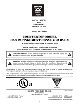
II. OVEN COMPONENTS – see Figure 1-1.
A. Conveyor Drive Motor: Moves the conveyor.
B. Crumb Pans: Catch crumbs and other materials that drop
through the conveyor belt. One crumb pan is located at
each end of the conveyor.
C. Conveyor: Moves the food product through the oven.
D. End Plugs: Allow access to the oven’s interior.
E. Eyebrows: Can be adjusted to various heights to prevent
heat loss into the environment.
F. Window: Allows the user to access food products inside
the baking chamber.
G. Machinery Compartment Access Panel: Allows access
to the oven’s interior and control components. No user ser-
viceable parts are located in the machinery compartment.
H. Serial Plate: Provides specications for the oven that affect
installation and operation. Refer to Section 2, Installation
for details.
I. Control Panel: Location of the operating controls for the
oven. Refer to Section 3, Operation, for details.
J. Photo Cell: Turns oven On when beam is interrupted.
Not Shown:
K. Gas Burner (gas ovens): Heat air, which is then projected
to the air ngers by the blowers.
L. Blowers: Project hot air from the burner or heating element
to the air ngers.
M. Air Fingers: Project streams of hot air onto the food product.
SECTION 1 – DESCRIPTION
Figure 1-1. Oven Components

2P/N60250September28,2012
I. OVEN SPECIFICATIONS
Table 1-1 Dimensions Single Oven Double Oven Triple Ove
Overall Height 48-3/16″ (1219mm) 62-3/4″ (1575mm) 78-11/16″ (1981mm)
Overall Depth 60″ (1524mm) 60″ (1524mm) 60″ (1524mm)
Overall Length 76-1/2″ (1930mm) 76-1/2″ (1930mm) 76-1/2″ (1930mm)
Conveyor Width – belt width is 32″ 33-1/2″ (838mm) 33-1/2″ (838mm) 33-1/2″ (838mm)
or 2 × 15″ (381mm) or 2 × 15″ (381mm) or 2 × 15″ (381mm)
Shortened Exit Conveyor - 24″ Single Oven Double Oven Triple Ove
Overall Depth 52.75″ (1340mm) 52.75″ (1340mm) 52.75″ (1340mm)
Overall Length 69″ (1753mm) 69″ (1753mm) 69″ (1753mm)
* All other dimension are the same
Recommended Minimum Clearances
Rear of Oven to Wall 3″ (76mm) 3″ (76mm) 3″ (76mm)
Control end of conveyor to Wall 1″ (25.4mm) 1″ (25.4mm) 1″ (25.4mm)
Non-control end of conveyor to Wall) 1″ (25.4mm) 1″ (25.4mm) 1″ (25.4mm)
Table 1-2: General Specications PS740 GAS 32″ Belt 24″ Belt
Weight 1150 lbs. (522kg) 1150 lbs. (522kg)
Rated Heat Input 99,000 BTU (25,000kcal, 29 kW/hr) 99,000 BTU (25,000kcal, 29 kW/hr)
Maximum Operation Temperature 600°F / 315°C 600°F / 315°C
Air Blowers Two Blowers at 1900 RPM Two Blowers at 1900 RPM
Warmup Time 15 min. 15 min.
Table 1-3: Electrical specications for PS740G gas ovens
Main Blower Control Circuit Phase Freq Current Poles Wires
Voltage Voltage Draw
208-240VAC 208-240VAC 1Ph 50/60Hz 11-9.6 Amp 2 Pole 3 Wire (2 hot, 1 gd)
Table 1-4: Gas orice and pressure specications for PS740G gas ovens
Gas Main Orice I.D. Supply (Inlet) Orice (Manifold) Bypass
Type PS740G Pressure Pressure Pressure
Natural 0.1065″ (0.120mm) 8-12″ W.C. (19.9 - 29.9mbar) 3.5″ W.C. (8.7mbar) 0.25-0.3″ W.C. (0.6-0.8 mbar)
Propane 0.067″ (1.9mm) 11-14″ W.C. (27.4 - 34.9mbar) 10.0″ W.C. (24.9mbar) 0.9-1.0″ W.C. (2.2-2.5 mbar)
IMPORTANT – Additional electrical information is provided on the oven’s serial plate, and on the wiring diagram inside the
machinery compartment.
NOTE
Wiring Diagrams are contained in Section 5 of this Manual
and are also located inside the oven at the
bottom of the Control Panel.
Additional electrical information is provided on the oven's serial plate.
This Manual Must Be Kept For Future Reference
GAS ORIFICE AND PRESSURE SPECIFICATIONS (PER OVEN CAVITY) - CE OVENS
Supply(Inlet)Pressure
IT,PT,ES,SE,
Main UK,CH,IT,AT, SE,CH,AT,DK, BE,IE,IT,PT, Orice Rated
Gas Orice DK,FI NL DE BE,FR FI,DE,NL ES,UK (Manifold) Heat
Type dia.
I
2H
I
2L
I
2E
I
2E+
I
3B/P
I
3+
Pressure Input
G20 0.120″ 20 -- 20 20 -- -- 11.21 22.36
(3.05mm) mbar mbar mbar mbar kW-hr.
G25 0.120″ -- 25 -- -- -- -- 16.19 22.36
(3.05mm) mbar mbar kW-hr.
G30 0.075″ -- -- -- -- 29or50 28-30,37 26.2 22.59
(1.9mm) mbar or50mbar mbar kW-hr.

3 P/N60250September28,2012
SECTION 2 – INSTALLATION
WARNING – After any conversions, readjustments, or service work on the oven:
• Perform a gas leak test. • Test for proper combustion and gas supply.
• Test for correct air supply, particularly to the • Check that the ventilation system is in operation.
burner blower.
WARNING - Keep the appliance area free and clear of combustibles.
WARNING – The oven must be installed on an even (level) non-ammable ooring and any adjacent walls
must be non-ammable. Recommended minimum clearances are specied in the Description section
of this manual.
WARNING – Do not obstruct the ow of combustion and ventilation air to and from your oven. There
must be no obstructions around or underneath the oven. Constructional changes to the area where the
oven is installed shall not affect the air supply to the oven.
CAUTION: To reduce the risk of re, the appliance is to be mounted on oors of noncombustible construction
with noncombustible ooring and surface nish and with no combustible material against the underside thereof,
or on noncombustible slabs or arches having no combustible material against the underside thereof, such con-
struction shall in all cases extend not less than 12 inches (304mm) beyond the equipment on all sides.
CAUTION: For additional installation information, contact your local Authorized Service Agent.
NOTE – There must be adequate clearance between the oven and combustible construction. Clearance must
also be provided for servicing and for proper operation.
NOTE – An electrical wiring diagram for the oven is located inside the machinery compartment.
NOTE: All aspects of the oven installation, including placement, utility connections, and ventilation requirements,
must conform with any applicable local, national, or international codes. These codes supersede the require-
ments and guidelines provided in this manual.
NOTE: In the USA, the oven installation must conform to local codes. In the absence of local codes, gas oven
installations must conform with the National Fuel Gas Code, ANSI Z223.1. Gas and electric ovens, when installed,
must be electrically grounded in accordance with local codes, or in the absence of local codes, with the National
Electrical Code (NEC), or ANSI/NFPA70.
NOTE: In Canada, the oven installation must conform with local codes. In the absence of local codes, gas
oven installations must conform with the Natural Gas Installation Code, CAN/CGA-B149.1, or the Propane Gas
Installation Code, CAN/CGA-B149.2, as applicable. Gas and electric ovens, when installed, must be electrically
grounded in accordance with local codes, or in the absence of local codes, with the Canadian Electrical Code
CSA C22.2.
NOTE: In Australia, the oven installation must conform with local codes. In the absence of local codes, gas
oven installations must conform with the requirements of AS5601/AG601, Gas, Electricity, and any other relevant
statutory regulations.

4P/N60250September28,2012
3
2
4
6
5
1
PARTS LIST FOR SERIES PS740 GAS OVEN
INSTALLATION KIT
P/N 61452
(Two required for double oven)
(Three required for triple oven)
ITEM
NO. QTY PART NO. DESCRIPTION
1 1 22361-0001 FLEXIBLE GAS HOSE
2 1 61823 CONVEYOR END STOP
3 1 31461 CONVEYOR LEFT REAR STOP
4 1 42612 SERVICE AGENCY DIRECTORY
5 1 22500-0080 LABEL, MM
6 1 51054 ASSY, HANDLE & DOOR
Figure 2-1A. PS740-Series Gas Oven Installation Parts
PS740 24″ OVEN INSTALLATION
REQUIRED KITS AND EQUIPMENT
PS740 PS740 PS740 PS740
Gas Oven Single Oven DoubleOven TripleOven
Installation Option Base w/ OptionBase w/ OptionBase w/
TYPE OF INSTALLATION Kit 15″ Legs, 6″ Legs, Casters& Top
Casters & Top Casters & Top Kit
Kit Kit
P/N61452 P/N61123 P/N61457 P/N61458
PS740 Single Gas Oven 1 1
PS740 Double Gas Oven 2 1
PS740 Triple Gas Oven 3 1

5 P/N60250September28,2012
PS740 OVEN INSTALLATION
REQUIRED KITS AND EQUIPMENT
PS740 PS740 PS740 PS740
Gas Oven Single Oven DoubleOven TripleOven
Installation Option Base w/ OptionBase w/ OptionBase w/
TYPE OF INSTALLATION Kit 15″ Legs, 6″ Legs, Casters& Top
Casters & Top Casters & Top Kit
Kit Kit
P/N61033 P/N67025 P/N67026 P/N66164
PS740 Single Gas Oven 1 1
PS740 Double Gas Oven 2 1
PS740 Triple Gas Oven 3 1
3
2
4
6
5
1
PARTS LIST FOR SERIES PS740 GAS OVEN
INSTALLATION KIT
P/N 61033
(Two required for double oven)
(Three required for triple oven)
ITEM
NO. QTY PART NO. DESCRIPTION
1 1 22361-0001 FLEXIBLE GAS HOSE
2 1 61823 CONVEYOR END STOP
3 1 55027 CONVEYOR LEFT REAR STOP
4 1 42612 SERVICE AGENCY DIRECTORY
5 1 22500-0080 LABEL, MM
6 1 51054 ASSY, HANDLE & DOOR
Figure 2-1B. PS740-Series Gas Oven Installation Parts

6P/N60250September28,2012
Figure 2-2A. Model PS740 24″ Single Oven
Option Base with Legs and Top
PARTS LIST FOR PS740 SERIES 24″ SINGLE OVEN OPTION - BASE w/15″ LEGS & TOP
P/N 67027
HARDWARE BAG
5, 6, 7, 10 & 11
1
2
4
9
8
ITEM NO. QTY PART NO. DESCRIPTION
1 1 64943 COMPLETE BASE WELDMENT
2 4 66851 TOP PLATE, LEG WELDMENT
4 4 58930 SWIVEL CASTER FLAT PLATE
5 32 2000531 3/8″-16 × 1″ HEX SCREW, SST
6 32 21416-0001 3/8″ FLAT WASHER, SS
7 32 21422-0001 3/8″ SPLIT LOCK WASHER, ZP
8 1 22450-0228 RESTRAINT CABLE ASSEMBLY
9 1 61125 TOP COVER
10 2 59677 SCR, MS SL TR HD 10-32 × 2-1/2″
11 2 7A2S15 SCR, MS STR TRSHD 10-32 × 3/4″

7 P/N60250September28,2012
Figure 2-2B. Model PS740 32″ Single Oven
Option Base with Legs and Top
PARTS LIST FOR PS740 SERIES 32″ SINGLE OVEN OPTION - BASE w/15″ LEGS & TOP
P/N 67025
HARDWARE BAG
5, 6, 7, 10 & 11
1
2
4
9
8
ITEM NO. QTY PART NO. DESCRIPTION
1 1 66159 COMPLETE BASE WELDMENT
2 4 66851 TOP PLATE, LEG WELDMENT
4 4 58930 SWIVEL CASTER FLAT PLATE
5 32 2000531 3/8″-16 × 1″ HEX SCREW, SST
6 32 21416-0001 3/8″ FLAT WASHER, SS
7 32 21422-0001 3/8″ SPLIT LOCK WASHER, ZP
8 1 22450-0228 RESTRAINT CABLE ASSEMBLY
9 1 59560 TOP COVER
10 2 59677 SCR, MS SL TR HD 10-32 × 2-1/2″
11 2 7A2S15 SCR, MS STR TRSHD 10-32 × 3/4″

8P/N60250September28,2012
ITEM NO. QTY PART NO. DESCRIPTION
1 1 64943 COMPLETE BASE WELDMENT
2 4 66853 TOP PLATE, LEG WELDMENT
4 4 58930 SWIVEL CASTER FLAT PLATE
5 32 2000531 3/8″-16 × 1 HEX SCREW, SST
6 32 21416-0001 3/8″ FLAT WASHER, SS
7 32 21422-0001 3/8″ SPLIT LOCK WASHER, ZP
8 1 22450-0228 RESTRAINT CABLE ASSEMBLY
9 1 61125 TOP COVER
10 2 59677 SCR, MS SL TR HD 10-32 × 2-1/2″
11 2 7A2S15 SCR, MS STR TRSHD 10-32 × 3/4″
PARTS LIST FOR PS740 SERIES 24″ DOUBLE OVEN OPTION - BASE w/6″ LEGS & TOP
P/N 67028
HARDWARE BAG
5, 6, 7, 10 & 11
1
2
4
9
8
Figure 2-3A. Model PS740 24″ Double Oven
Option Base with Legs and Top

9 P/N60250September28,2012
ITEM NO. QTY PART NO. DESCRIPTION
1 1 66159 COMPLETE BASE WELDMENT
2 4 66853 TOP PLATE, LEG WELDMENT
4 4 58930 SWIVEL CASTER FLAT PLATE
5 32 2000531 3/8″-16 × 1 HEX SCREW, SST
6 32 21416-0001 3/8″ FLAT WASHER, SS
7 32 21422-0001 3/8″ SPLIT LOCK WASHER, ZP
8 1 22450-0228 RESTRAINT CABLE ASSEMBLY
9 1 59560 TOP COVER
10 2 59677 SCR, MS SL TR HD 10-32 × 2-1/2″
11 2 7A2S15 SCR, MS STR TRSHD 10-32 × 3/4″
PARTS LIST FOR PS740 SERIES 32″ DOUBLE OVEN OPTION - BASE w/6″ LEGS & TOP
P/N 67026
HARDWARE BAG
5, 6, 7, 10 & 11
1
2
4
9
8
Figure 2-3B. Model PS740 32" Double Oven
Option Base with Legs and Top

10P/N60250September28,2012
ITEM NO. QTY PART NO. DESCRIPTION
1 1 64943 COMPLETE BASE WELDMENT
2 4 45209 QUAD OUTRIGGER WELDMENT
3 2 22290-0010 SWIVEL CASTER, FLAT PLATE
4 2 22290-0009 SWIVEL CASTER, FLAT PLATE, W/BRAKE
5 4 45206 INSERT,QUAD ADJUSTMENT FOOT
6 4 45205 SPACER,QUAD CASTER
7 32 A27727 3/83 -16x1-1/4 HEX BOLT
8 32 A21924 3/83 FLAT WASHER, SS
9 32 21422-0001 3/83 SPLIT LOCK WASHER, ZP
10 16 21172-0004 3/83 -16 NYLON INSULATED LOCKNUT, ZC
11 8 2001048 1/23 -13 x 1-3/8 18-8 HEX CAPSCREW
12 8 A27750 1/23 18-8 FLAT WASHER
13 8 21422-0016 1/23 18-8 LOCK WASHER
14 2 59677 SCR, MS SL TR HD 10-32X2-1/2
15 1 22450-0228 RESTRAINT CABLE ASSEMBLY
16 1 61125 TOP COVER
17 2 7A2S15 SCR, MS STR TRSHD 10-32X3/4″
PARTS LIST FOR PS740 SERIES 24″ TRIPLE OVEN OPTION - BASE w/CASTERS & TOP
P/N 64946
HARDWARE BAG
7, 8, 9, 10, 11, 12,
13, 14, & 17
1
2
3
16
15
6
5
4
Figure 2-4A. Model PS740 24″ Triple Oven
Option Base with Outriggers and Top

11 P/N60250September28,2012
ITEM NO. QTY PART NO. DESCRIPTION
1 1 66159 COMPLETE BASE WELDMENT
2 4 45209 QUAD OUTRIGGER WELDMENT
3 2 22290-0010 SWIVEL CASTER, FLAT PLATE
4 2 22290-0009 SWIVEL CASTER, FLAT PLATE, W/BRAKE
5 4 45206 INSERT,QUAD ADJUSTMENT FOOT
6 4 45205 SPACER,QUAD CASTER
7 32 A27727 3/83 -16x1-1/4 HEX BOLT
8 32 A21924 3/83 FLAT WASHER, SS
9 32 21422-0001 3/83 SPLIT LOCK WASHER, ZP
10 16 21172-0004 3/83 -16 NYLON INSULATED LOCKNUT, ZC
11 8 2001048 1/23 -13 x 1-3/8 18-8 HEX CAPSCREW
12 8 A27750 1/23 18-8 FLAT WASHER
13 8 21422-0016 1/23 18-8 LOCK WASHER
14 2 59677 SCR, MS SL TR HD 10-32X2-1/2
15 1 22450-0228 RESTRAINT CABLE ASSEMBLY
16 1 59560 TOP COVER
17 2 7A2S15 SCR, MS STR TRSHD 10-32X3/4″
PARTS LIST FOR PS740 SERIES 32″ TRIPLE OVEN OPTION - BASE w/CASTERS & TOP
P/N 66164
HARDWARE BAG
7, 8, 9, 10, 11, 12,
13, 14, & 17
1
2
3
16
15
6
5
4
Figure 2-4B. Model PS740 32″ Triple Oven
Option Base with Outriggers and Top

12P/N60250September28,2012
III. VENTILATION SYSTEM
B. Recommendations
NOTE THAT THE HOOD DIMENSIONS SHOWN IN
FIGURE 2-5 ARE RECOMMENDATIONS ONLY.
LOCAL, NATIONAL AND INTERNATIONAL CODES
MUST BE FOLLOWED WHEN INSTALLING THE
VENTILATION SYSTEM. ANY APPLICABLE CODES
SUPERSEDE THE RECOMMENDATIONS SHOWN IN THIS
MANUAL. IN AUSTRALIA COMPLIANCE TO REGULATIONS
AS5601/AG601 IS MANDATORY.
The rate of air ow exhausted through the ventilation system
may vary depending on the oven conguration and hood de-
sign. Consult the hood manufacturer or ventilation engineer
for these specications.
To avoid a negative pressure condition in the kitchen area,
return air must be brought back to replenish the air that was
exhausted. A negative pressure in the kitchen can cause
heat- related problems to the oven components as if there
were no ventilation at all. The best method of supplying return
air is through the heating, ventilation and air conditioning
(HVAC) system. Through the HVAC system, the air can be
temperature-controlled for summer and winter. Return air can
also be brought in directly from outside the building, but detri-
mental effects can result from extreme seasonal hot and cold
temperatures from the outdoors.
NOTE: Return air from the mechanically driven system must
not blow at the opening of the baking chamber. Poor
oven baking performance will result.
C. Other ventilation concerns
• Special locations, conditions, or problems may require the
services of a ventilation engineer or specialist.
• Inadequate ventilation can inhibit oven performance.
• It is recommended that the ventilation system and duct
work be checked at prevailing intervals as specied by the
hood manufacturer and/or HVAC engineer or specialist.
A. Requirements
CAUTION: Gas oven installations REQUIRE a mechanically
driven ventilation system with electrical exhaust
air sensing control.
A mechanically driven ventilation system is STRONGLY
RECOMMENDED for electric oven installations.
PROPER VENTILATION OF THE OVEN IS THE RESPON-
SIBILITY OF THE OWNER.
IMPORTANT
Where national or local codes re-
quire the installation of re sup-
pression equipment or other
supplementary equipment, DO NOT
mount the
equipment directly to the oven.
MOUNTING SUCH EQUIPMENT ON
THE OVEN MAY:
• VOID AGENCY CERTIFICATIONS
• RESTRICT SERVICE ACCESS
• LEAD TO INCREASED SERVICE
EXPENSES FOR THE OWNER
Figure 2-5. Ventilation System
18″ (458mm)
minimum
(Typical - both
ends of oven)
2″ (51mm)
minimum
3″ (76mm)
minimum
8″ (203mm)
minimum

13 P/N60250September28,2012
IV. ASSEMBLY
A. Top Panel and Base Pad Assembly
1. Install the four leg extensions onto the base pad using
the 3/8″-16 × 1″ screws, 3/8″ flat washers, and
3/8″ lockwashers supplied in the Base Pad Kit. See
Figure 2-6. Check that the nished sides of each leg exten-
sion face OUTWARDS. One rear leg should be attached
using three 3/8″-16 × 1″ screws and the 3/4″ eyebolt, as
shown in Figure 2-6. This eyebolt acts as the anchor point
for the restraint cable assembly (see Part C, Restraint
Cable Installation).
2. If your oven is equipped with the lower shelf, position it
in place as shown in Figure 2-6. Check that the lip on the
shelf faces DOWN. Seal joint between leg and shelf with
NSF listed silicone.
3. Install one caster onto each leg extension, as shown in
Figure 2-7. Use the 3/8″-16 × 1″ screws, 3/8″ at wash-
ers, and 3/8″ lockwashers supplied in the Installation Kit.
The locking casters should be installed at the FRONT of
the oven. The non-locking casters should be installed at
the REAR of the oven.
4. Install the lower oven cavity onto the base pad.
See Fig 2-7.
5. For single ovens ONLY:
Install the top panel using the screws included in the base
pad kit, as shown in Figure 2-8. Then, skip ahead to Part
C, Restraint Cable Installation.
For double or triple ovens:
Continue on to Part B, Stacking. Note that the top panel
should NOT be installed for double and triple ovens until
after stacking the oven cavities.
Figure 2-6. Leg extension and casters installation
Figure 2-7. Base pad Installation
Assembled�
base pad
Bottom oven�
cavity
#10-32 × 3/4″
screw length
Top
panel
Figure 2-8. Top panel installation
1/2″ at
washer
1/2″ lock
washer
1/2″-13 × 1-1/4″
hex screw
#10-32 × 2-1/2″
screw length

14P/N60250September28,2012
NOTE: DO NOT install top panel onto double or triple
ovens until AFTER stacking the oven cavities. See
Part B, Stacking.
B. Stacking
For single ovens, skip ahead to Part C, Restraint Cable
Installation.
IMPORTANT
Middleby Marshall STRONGLY RECOMMENDS that PS740
Gas oven cavities be stacked BY AUTHORIZED PERSONEL.
Contact your Middleby Marshall Authorized Service Agent for
complete stacking instructions.
1. Stack an oven cavity on top of the lower oven. Check
the following:
• All four sides of the lower lip (on the bottom edge of
the oven cavity) overlap the top of the lower oven
• The oven is level
• The oven is rmly seated
See Figure 2-9.
2. For triple ovens, repeat Step 1 to install the top
oven cavity.
3. Install the top panel using the screws included in the base
pad kit, as shown in Figure 2-10.
Figure 2-9. Stacking
Figure 2-10. Top panel installation
C. Restraint Cable Installation
Because the oven is equipped with casters, a restraint cable
assembly must be installed to limit the movement of the appli-
ance without depending on the connector and the quick discon-
nect device or its associated piping. One end of the cable is
anchored to the eyebolt on the rear surface of the oven’s base
pad, while the other is anchored to the wall. See Figure 2-11.
After connecting the restraint cable, move the oven to its nal
location. Adjust the bottom (hex) sections of the feet so that
the casters are off the oor. For quad ovens, lock the two
front casters.
#10-32 × 3/4″
screw length
Top
panel
Figure 2-11. Installing the Restraint Cable
Wall of structure
Restraint cable assembly
3/4″ (19mm)
eyebolt
3/8″-18 × 1″
eyebolt on
rear leg
extension
#10-32 × 2-1/2″
screw length

15 P/N60250September28,2012
D. Conveyor Installation
1. Unfold the conveyor as shown in Figure 2-12. Then,
begin to slide the conveyor into the end of the oven. The
conveyor can only be installed from the end of the oven
with the drive motor.
2. Continue moving the conveyor into the oven until the frame
protrudes equally from each end of the oven. Check that
the crumb tray supports located on the underside of the
conveyor frame rest rmly against the lower end plugs,
as shown in Figure 2-13.
3. When the conveyor is positioned properly, check for
freedom of movement of the conveyor belt by pulling it
for about 2-3 feet (0.6-1.0m) with your ngers. The drive
and idler shafts must rotate smoothly, and the belt must
move freely without rubbing on the inside of the oven.
4. Check the tension of the conveyor belt as shown in
Figure 2-14. The belt should lift about 1″ (25mm).
DO NOT OVERTIGHTEN THE CONVEYOR BELT.
NOTE: If necessary, the belt tension can be adjusted by
turning the conveyor adjustment screws, located
at the idler (non-control) end of the conveyor. See
Figure 2-14.
Figure 2-12. Conveyor installation
Figure 2-13. Conveyor placement
Figure 2-14. Conveyor Belt tension
Folded
frame
Crumb tray
support
bracket
End plug
Conveyor
placed in
oven
Adjustment
screws (2) on
idler end of
conveyor
Idler end (with belt tension
adjustment screws)
Drive end (with
drive sprocket)
1″ (25mm) verti-
cal deection

16P/N60250September28,2012
5. If it is necessary to add or remove conveyor links to achieve
the correct tension, OR if it is necessary to reverse the
conveyor belt for correct orientation, the belt will need to
be removed from the conveyor frame. If this is necessary,
perform the following procedure:
• Remove the conveyor assembly from the oven and place
it at on the oor.
• Remove the master links using long-nose pliers. Then,
roll up the belt along the length of the conveyor frame.
• Add or remove belt links as necessary to achieve the
correct belt tension.
• Replace the belt on the conveyor frame. Check that the
conveyor belt links are oriented as shown in Figure 2-15,
and that the smooth side of the conveyor belt faces UP.
• Connect the inside master links. Check that the links
are oriented as shown in Figure 2-15.
• Connect the outside master links. Note that the outside
master links each have an open hook on one side. This
hook aligns with the hooks along the sides of the other
conveyor links. See Figure 2-15.
• Replace the conveyor into the oven.
Figure 2-15. Conveyor and Master Link orientation
E. Final Assembly
1. Install the crumb trays underneath the conveyor as shown
in Figure 2-16.
REVERSING THE CONVEYOR BELT
Remove the conveyor from the oven and nd the master link
location. Remove master links and remove the belt from the
conveyor frame. Reassemble the belt back onto the frame (in
the reverse direction) and reinstall the master links. Replace
the conveyor assembly in the oven.
RESETTING DIRECTION JUMPER
Locate Jumper P1 on the conveyor control board. Move jumper
from terminals 1 and 2, and replace onto terminals 2 and 3.
CAUTION: Shock hazard in compartments electrical lters
are electrically alive.
SWITCHING PHOTO DETECTOR
CAUTION: Disconnect Power Before Switching Photo eye.
Remove the three screws securing the access door to the unit.
Open the access door and disconnect the connector tting to
the photo eye assembly. Remove the two screws securing the
photo eye assembly to the control box. Remove the four nuts
securing the photo eye to the housing. Rotate the photo eye
180 degrees and resecure the photo eye with the four nuts.
On the opposite control box, remove the two screws holding the
cover where the photo eye assembly will be positioned. Secure
the photo eye assembly in position with the two screws. Place
the photo eye cover on the opposite control box, where the
photo eye assembly was removed, and secure the two screws.
Secure the access door with the three screws.
Remove the three screws securing the access door on the
opposite side. Open the access door, where the photo eye is
now positioned, and connect the photo eye connector tting.
Secure the access door with the three screws.
Apply power to the unit. Adjust the photo eye height by loosening
the two screws securing the photo eye assembly and sliding
the photo eye assembly either up or down, such that the beam
is approximately 1/4 inch above the belt.
Note: This is MUCH easier in reduced light.
Replace all covers.
VI. ELECTRICAL SUPPLY
WARNING: Authorized installation personnel normally ac-
complish the connections for the ventilation
system, electric supply, and gas supply, as
arranged by the customer. Following these
connections, the factory-authorized installer
can perform the initial startup of the oven.
NOTE: The electric supply installation must satisfy the require-
ments of the appropriate statutory authority such as the
National Electrical Code, CSA C22.2; the Australian
Code AG601; or other applicable regulations.
NOTE: The electric supply connection must meet all national
and local electrical code requirements.
Check the oven serial plate before making any electric supply
connections. Electric supply connections must agree with data
Figure 2-16. Crumb Trays
Crumb tray
insertion
Direction
of travel
CORRECT
master link
position
Incorrect
master link
position
CONVEYOR BELT REVERSAL
Conveyor belt reversal consists of three steps:
1. Physically reversing the conveyor belt.
2. Resetting direction jumper on the conveyor control board.
3. Switching the photo detector.
/