GE AZ52H12DAB User manual
- Category
- Split-system air conditioners
- Type
- User manual

3
Important Safety Information
10
Installation Instructions
Important Electrical Safety
Adjustments and Auxiliary Controls
4
Operating Instructions
The Controls on Your Zoneline
Care of Product
20
Helpful Information
Things That Are Normal
21
If Something Goes Wrong
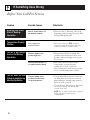
Before You Call For Service
GE Service Numbers
Warranty
GE Appliances
Zoneline
®
Owner’s Manual
Zoneline Heat Pump Model
5200 Series
GE Answer Center
®
800.626.2000
49-7367

Welcome to the GE family. We’re
proud of our quality products and
we believe in dependable service.
You’ll see it in this easy-to-use
manual and you’ll hear it in the
friendly voices of our customer
service department.
Best of all, you’ll experience
these values each time you enjoy
the comfort of your Zoneline.
That’s important, because your
new Zoneline will be part of your
family for a long time.
Welcome
Staple your receipt to the inside back
cover of this manual. You will need it
to obtain service under warranty.
Write down the model and serial
numbers here.
They are on a label
behind the room cabinet on the
base pan.
Model number
Serial number
Date of purchase
Before using
your
Zoneline
Need Help?
Before you call for service,
there are a few things you can
do to help us serve you better.
Read this manual.
It contains
instructions to help you use and
maintain your Zoneline properly.
Save time and money.
Check the
section titled
If Something Goes
Wrong
before calling. This section
was designed to solve common
problems that might occur.
If you do need service, you can
relax knowing help is only a phone
call away. Toll-free customer service
numbers are included in the back
of this manual. Or call the
GE
Answer Center
®
at 800.626.2000,
24 hours a day, 7 days a week.
Help us
help you
800.626.2000
2
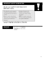
Start Here!

• This Zoneline must be properly
installed in accordance with the
Installation Instructions before it
is used.
• Repair or replace immediately
all electric service cords that have
become frayed or otherwise
damaged.
• Unplug or disconnect the
Zoneline at the fuse box or
circuit breaker before making
any repairs.
NOTE:
We strongly recommend
that any servicing be performed
by a qualified individual.
SAVE THESE INSTRUCTIONS
3
Replacing an
existing unit?
For details see the
Installation
Instructions
in the back of this
manual.
IMPORTANT SAFETY INFORMATION
READ ALL SAFETY INFORMATION
BEFORE USING

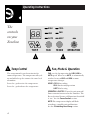
The temp control is used to maintain the
room temperature. The compressor will cycle
on and off to keep the room at the same level
of comfort.
Press the + pad to raise the temperature.
Press the – pad to lower the temperature.
FAN
—sets the fan operation for
HIGH, LOW
or
AUTO
speed. When set at
AUTO
, it automatically
switches between
LOW
and
HIGH
as room
temperature changes.
MODE
—
COOL—
For cooling
FAN—
For fan-only operation
HEAT—
For heating
OPERATION—ON/STOP
—Turns the unit on or off.
Power remains connected to the Zoneline. The
Freeze Sentinel feature still functions if switch E
is “on.” See the
Freeze Sentinel
section.
NOTE:
The temperature display will flash
to indicate a possible unit malfunction.
See the
If Something Goes Wrong
section.
4
Operating Instructions
The
controls
on your
Zoneline
2
2
1
Temp Control Fan, Mode & Operation
1
MODETEMP FAN OPERATION
HIGH
LOW
AUTO
COOL
FAN
HEAT
ON
STOP

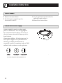
5
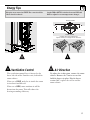
Energy Tips
Keep the vent control at
CLOSE
. The room air will be
filtered and circulated.
Set the
FAN
at
AUTO
. It switches between
LOW
and
HIGH
to adjust for room temperature changes.
The ventilation control lever is located at the
lower left side of the Zoneline unit, behind the
room cabinet.
When set at
CLOSE
, only the air inside the room
is circulated and filtered.
When set at
OPEN
, some outdoor air will be
drawn into the room. This will reduce the
heating or cooling efficiency.
43
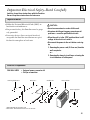
Ventilation Control Air Direction
To adjust the air direction, remove the room
cabinet. Remove the 7 louver screws that
hold the louvers in place. Flip the louver
section 180
°, replace the screws and the
room cabinet.
3 4
OPEN
CLOSE
Vent
control
Remove the room cabinet and
flip the louvers to change the air direction.
Louver screws
Louver screws

Operating Instructions
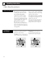
Other Zoneline features
Additional controls are located
behind the room cabinet.
To remove:
Pull out at the bottom to
release it from the tabs. Then lift up.
To replace:
Place the tabs over
the top rail. Push inward at the
bottom until it snaps into place.
To Remove the
Room Cabinet
6
Heat pumps can save money by
removing heat from the outside
air—even when the outside
temperature is below freezing—
and releasing that heat indoors.
To get the best performance from
your heat pump, don’t change the
room thermostat very often.
Raising the heat setting 2–3
degrees will cause the Zoneline to
use its electric heating elements in
order to reach the new temperature
setting quickly.
There is a three minute minimum
compressor run time at any setting
to prevent short cycling.
The indoor fan motor starts before
the compressor and stops after the
compressor cycles off.
The electric heating elements use
much more electricity than heat
pumps and cost more to operate.
About Your Heat Pump
1
2
1
2

Switch E controls the Freeze
Sentinel. When the switch is
DOWN
the Freeze Sentinel automatically
turns on the resistance heater and
fan if the room temperature (sensed
at the unit) drops to approximately
40
° F. It will turn the heater off when
the temperature reaches about 45° F.
The unit leaves the factory with the
Freeze Sentinel in the
DOWN
(on)
position.
The Freeze Sentinel helps prevent
plumbing damage in the room due
to sub-freezing temperatures.
If the Freeze Sentinel is set, it is
active as long as power to the
unit is on.
NOTE: The owner is responsible for
checking the Freeze Sentinel switch
and ensuring it is in the desired
setting.
Freeze Sentinel
™
7
The fan switch #9 is located behind
the room cabinet.
This switch is set at continuous fan
(
DOWN
) at the factory to provide
continuous fan operation in cool
or heat modes. Leaving the switch
in the continuous fan setting allows
continuous circulation of room air
and will result in a more balanced
temperature throughout the room.
If you want the fan to cycle on
and off with the compressor or
with the heater, move the switch
to cycle fan (
UP
).
Fan Switch
UP
DOWN
1234 56789A
B
CDE
UP
DOWN
1234 56789A
B
CDE
Down—Continuous Fan
Up—Cycle Fan
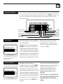
Auxiliary Controls
Auxiliary Controls
The auxiliary controls are located behind the room cabinet on the front of
the unit control box. The factory settings will be in the
DOWN
position. The
owner is responsible for checking switches and ensuring they are in the
desired position.
Auxiliary Controls
1
2
3
4 5 6 7 9A8 BCDE
UP
DOWN
Freeze
Sentinel
UP: Cycle fan
DOWN: Continuous fan
Remote Control (Class 2)
Self
Diagnostics
CDC (Load
Shedding)
All Time Low Fan
All Electric Heat
Boost
Temp Limit Cool
Temp Limit Heat

8
Operating Instructions
Care & Cleaning
Turn the Zoneline off and
disconnect the power supply.
To clean, use water and a mild
detergent. Do not use bleach or
abrasives. Some commercial
cleaners may damage the plastic
parts.
Room Cabinet
and Case
The coils on the outdoor side of
the Zoneline should be checked
regularly. If they are clogged with
dirt or soot they may be
professionally steam cleaned, a
service available through your
GE service outlet. You will need to
remove the chassis to inspect the
coils because the dirt build-up
occurs on the inside.
Outdoor Coils
In some installations, dirt or other
debris may be blown into the unit
from the outside and settle in the
base pan (the bottom of the unit).
In some areas of the United States
a “gel-like” substance may be seen
in the base pan.
Check it periodically and clean it
out, if necessary.
Base Pan
Clean the outside coils
regularly.
Grille
Coils

Turn the Zoneline off before cleaning.
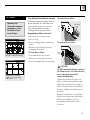
The most important thing you can
do to maintain the Zoneline is to
clean the filter at least every 30
days. Clogged filters reduce
cooling, heating and air flow.
Keeping these filters clean will:
• Decrease cost of operation.
• Save energy.
• Prevent clogged heat exchanger
coils.
• Reduce the risk of premature
component failure.
To clean the air filters:
• Vacuum off the heavy soil.
• Run water through the filters.
• Dry thoroughly before replacing.
To remove the air filters:
To replace the air filters:
CAUTION:
DO NOT operate the Zoneline without
the filters in place. If a filter becomes
torn or damaged it should be
replaced immediately.
Operating without the filters in
place or with damaged filters will
allow dirt and dust to reach the in-
door coil and reduce the cooling,
heating, airflow and efficiency of
the unit.
Replacement filters are available
from your salesperson, GE dealer,
GE Service and Parts Center
or authorized Customer Care®
servicers.
Air Filters
9
Pull
up
Push
down
2 air filters
FRONT
FRONT
Operating Tip:
To maintain optimum
performance, clean
the filters at least
every 30 days.
Dirty filter—Needs cleaning
Clogged filter—Greatly
reduces cooling, heating
and airflow.

Installation Instructions
Read carefully
If you have any questions, call the GE Answer Center at 800.626.2000.
•
Use the correct wall case.
This chassis is designed to be installed in a GE
plastic or insulated metal wall case. This mini-
mizes condensation from forming on the room
side of the case. If the current wall case is not
insulated, you can reduce the possibility of
condensation forming by installing insulation
kit RAK901L, available where you purchased
the chassis.
•
Use the correct outdoor grille.
You should use the outdoor grilles shown on
the “Essential Elements” label on the top of
the chassis.
• If an existing grille is not replaced, capacity and
efficiency will be reduced and the unit may fail
to operate properly or fail prematurely. A
deflector kit, RAK40, may be used with grilles
that were not designed for your new GE
Zonelines. The RAK40 contains air deflectors
and gaskets that mount to the chassis to direct
the hot exhaust air away from the air intake to
allow the unit to function properly. The grille
must have a 65% minimum free area.
• Any vertical deflectors in the existing rear grille
should be removed to decrease condenser air
recirculation which can cause the unit to
“short-cycle” and lead to premature compo-
nent failure.
•
Replacing a ducted chassis.
New ducted installation—If this unit is to be
installed in a new ducted application using a
duct adaptor kit, the kit must be installed before
the chassis is placed in the wall case. The installa-
tion instructions are packed with the kit.
Existing ducted installation—Replacement of an
existing ducted unit may require different com-
ponents. Request this information from your
sales representative.
• Replacing 230/208 volt units.
See page 12.
• Replacing 265 volt units.
See page 13.
Replacing an Existing Unit?
Check the “Essential
Elements” label for
important information.
10
Mounting
plate
Duct
Case

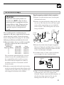
Important Electrical Safety—Read Carefully
Installer: Leave these instructions with the Zoneline.
Owner: Keep these instructions for future use.
• Follow the National Electrical Code (NEC) or
local codes and ordinances.
• For personal safety, this Zoneline must be prop-
erly grounded.
• Protective devices (fuses or circuit breakers)
acceptable for Zoneline installations are speci-
fied on the nameplate of each unit.
CAUTION:
•
Do not use an extension cord with this unit.
•
Aluminum building wiring may present special
problems—consult a qualified electrician.
•
When the unit is in the STOP position there is still
voltage to the electrical controls.
• Disconnect the power to the unit before servicing
by:
1 Removing the power cord (if it has one) from the
wall receptacle.
or—
2 Removing the branch circuit fuses or turning the
circuit breakers off at the panel.
Important Notes
YOU WILL NEED: • Universal power connector kit
• Phillips screwdriver
Zoneline Components
Exterior grille/louver** Wall case** Zoneline unit Room cabinet*
Power supply kit**
*Shipped with the Zoneline unit
**Check the “Essential Elements” list on the unit
11

12
Installation Instructions
1
Remove the room cabinet.
2
Install the power supply kit per the
instructions in the kit.
3
See the special instructions below for
applicable supply voltages.
4
Reinstall the room cabinet.
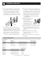
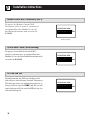
How to Connect
A power supply kit must be used to supply
power to the Zoneline unit. The appropriate
kit is determined by the voltage, the means of
electrical connection and the amperage of the
branch circuit.
Connections of 208 or 230 volt circuits may be
with a power supply kit or a junction box kit.
All wiring, including installation of the
receptacle, must be in accordance with the NEC
and local codes, ordinances and regulations.
TTaannddeemm PPeerrppeennddiiccuullaarr LLaarrggee TTaannddeemm
15 Amp. 20 Amp. 30 Amp.
230/208 Volt Electrical Supply
Electrical wiring wall outlets 230/208 volts.
Power supply kit

These models must be installed using the
appropriate GE power supply kit for the branch
circuit amperage and the electrical resistance
heater wattage desired. See page 14. One of the
following installation methods must be used:
A
Electrical subbase kits are available to provide
a flexible enclosure for direct connection.
Branch Circuit
and Chassis Proper GE Power
Amperage Rating Subbase Kit Supply Kit
15 RAK204E15 RAK5152
15 RAK204E15 RAK5172
20 RAK204E20 RAK5202
30 RAK204E30 RAK5302
The instructions provided with the selected
subbase kit must be carefully followed. It is
the responsibility of the installer to ensure
that connection of components is done in
accordance with these instructions and all
electrical codes.
B
For direct connection to branch circuit wiring
inside the provided junction box without using
a subbase kit, the cord is to be cut and the wire
ends stripped and connected as follows.
Steps for preparing cordset for direct connection:
1
Remove the junction box cover by taking out
the front four screws.
2
Remove the junction box by taking out the top
rear screw. Note how the slot at the lower right
corner of the junction box serves to hold the
corner in place. This will help when the box is
being reinstalled.
3
Remove the cordset from the power supply kit.
Measure 4
″down the cord from where it emerges
from the back of the nylon plastic connector and
cut the cord through at this point.
4
Carefully remove 3″ of the cordset insulation
so as to expose the three insulated wires.
5
Strip 3/4″ of the insulation away at the end of
each of the three wires (L1, Neutral and
Ground). Plug the connector fully into place in
the chassis mating connector. Be sure the
locking tabs at the sides are engaged.
265 Volt Electrical Supply
WARNING
Connection of this 265V product to a
branch circuit
MUST
be done by direct
connection to be in compliance with the
National Electric Code. Plugging of this
unit directly into a building mounted
exposed receptacle is not permitted
by code.
13
Slot in
junction box
Chassis
connector
Junction
box cover
Junction box
Tab on
chassis
3/4″
4″
3″
Connector

Installation Instructions
6
Use the round knockout at the bottom of the
junction box to attach conduit coming from
the branch circuit. Remove the knockout,
attach the conduit and bring wires into the
junction box. Leave 6
″of wire free at the end
of the conduit to allow connections to be made.
7
If a fuse and fuseholder are to be used, the
knockout at the top of the box is for mounting
of a Buss Fuseholder. Be sure the fuse and
fuseholder are of the same rating as the branch
circuit. Leadwires at the fuse can be either
soldered in place or attached using UL-listed,
1/4″ female (receptacle) crimp connectors.
8
Reinstall the junction box by engaging the tab
at the lower rear, aligning the screw hole at the
top and driving the one screw until secure. Be
sure that all wire leads are inside the box and
not pinched between the box and the chassis.
The green insulated ground wire from the
chassis
MUST
be connected to the branch
circuit ground wire.
9
Make all wire connections
by using appropriate
UL-listed electrical
connectors and techniques
(black to black, white to
white and green to green).
10
Carefully tuck all wires and connections back
inside the junction box. Be sure there are no
loose connections or stray uninsulated wires
exposed.
11
Place the junction box cover in place.
Replace the four screws removed earlier
and tighten securely.
12
Discard the unused portion of the plug and
the cordset.
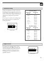
Power Connection Chart
230/208 Volt
Power Wall Plug Heater Wattage
Supply Kits Configuration Circuit Protective Device @ 230/208 Volts
RAK3152 Tandem 15 Amp Time Delay fuse 2.55/2.09 KW
RAK3202 Perpendicular 20 Amp Time Delay fuse 3.45/2.82 KW
RAK3302* Large Tandem 30 Amp Time Delay fuse 5.00/4.10 KW
265 Volt
Power Heater Wattage
Supply Kits Circuit Protective Device @ 265 Volts
RAK5152 15 Amp Time Delay fuse 1.7 KW
RAK5172 15 Amp Time Delay fuse 3.0 KW
RAK5202 20 Amp Time Delay fuse 3.7 KW
RAK5302* 30 Amp Time Delay fuse 5.0 KW
*Not recommended for use on 7000 BTUH units.
14
Conduit
Conduit

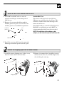
1
The RAB71 or RAB77 wall case must be
properly installed per instructions packed
with the case.
2
Remove the corrugated stiffener and the
outdoor protective panel. Use the slit in the
outdoor panel as a handhold and push out.
3
Install the exterior grille from the room side
following instructions packed with the grille.
Insulated Wall Case
This chassis is designed to be installed in a
GE plastic or an insulated steel wall case. This
minimizes condensation from forming on the
room side of the case.
The RAB71 wall case is insulated. Insulation kit
RAK901L is available for use with RAB77 or
existing uninsulated wall cases when needed.
NOTE: For installation with a subbase or duct
adaptor, see the instructions packed with those kits.
Protective
panel
Slit
Stiffener
Install the Wall Case and the Exterior Grille
1
1
Carefully remove shipping tape, if there is any,
from the room cabinet and vent door.
2
Remove the room cabinet by pulling it out at
the bottom to release it, then lift it up to clear
the rail along the unit top.
Remove the Shipping Tape from the Room Cabinet
2
Shipping tape
2
1
15

Installation Instructions
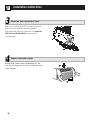
16
Slide the unit into the wall case and secure with
four screws through the unit flange holes.
If an insulated wall case is needed, see
Install the
Wall Case and Exterior Grille
section on the
previous page.
Install the Unit into the Wall Case
3
Reinstall the room cabinet by hooking the top
over the rail along the unit top, then pushing it in
at the bottom.
Replace the Room Cabinet
4
1
2

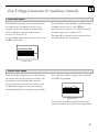
Low Voltage Connectors & Auxiliary Controls
The Boost Heat Option increases the Zoneline
air temperature by adding electric heat to
supplement the heat pump. It automatically
turns on when the outside temperature is
between 25
° F and 45° F.
To set the Boost Heat Option, move switch #8 to
the
UP
(on) position.
If the Zoneline is controlled by a wall thermostat
and Boost switch #8 is set to the
UP
(on)
position, only electric heat is available when the
outdoor temperature is below 45° F.
The Boost Heat Option is more expensive than
heating with the heat pump only.
UP
DOWN
1234 56789A
B
CDE
Boost Heat Option
Auxiliary controls
The Electric Heat Option increases the Zoneline
air temperature by using electric heat only. The
heat pump is not used to produce any heat.
If you want warmer air from the Zoneline and
the Boost Heat Option is not warm enough,
this option will provide the hottest air available.
To set the Electric Heat Option, move switch #7
to the
UP
(on) position.
Using the Electric Heat Option is much more
expensive than heating with the heat pump only.
UP
DOWN
1234 56789A
B
CDE
Electric Heat Option
Auxiliary controls
17

Installation Instructions
To operate the Remote Control/Wall
Thermostat (Class 2) switch A, you must use
an Optional Interface Module kit. See the
Installation Instructions with accessory kit
RAK0IM.
UP
DOWN
1234 56789A
B
CDE
Remote Control/Wall Thermostat (Class 2)
To operate Central Desk Control (CDC),
switch C, you must have an Optional Interface
Module kit. See the Installation Instructions with
accessory kit RAK0IM.
UP
DOWN
1234 56789A
B
CDE
Central Desk Control (Load Shedding)
Switch B controls the All-Time Low Fan and is
only effective with a Remote Control Thermostat.
This function causes the indoor fan to operate at
low speed. If the switch is
DOWN
(off) the fan will
run in high speed. If the switch is
UP
(on) the fan
will run in low speed.
UP
DOWN
1234 56789A
B
CDE
All-Time Low Fan
18
Auxiliary Controls

Temperature limiting can reduce energy costs
by limiting the lowest temperature that can be
set for cooling and the highest temperature that
can be set for heating. Temperature limiting is
controlled by setting the first six auxiliary
switches.
The first three are used to select cooling range
limits and the next three are used to select
heating range limits.
COOLING LIMITS
Limit Switch Temp Range
UP/On F.
None 60 to 85
1 64 to 85
1 & 2 66 to 85
2 68 to 85
2 & 3 70 to 85
1 & 2 & 3 72 to 85
1 & 3 74 to 85
3 76 to 85
HEATING LIMITS
Limit Switch Temp Range
UP/On F.
None 60 to 85
4 60 to 80
4 & 5 60 to 78
5 60 to 76
5 & 6 60 to 74
4 & 5 & 6 60 to 72
4 & 6 60 to 70
6 60 to 65
UP
DOWN
1234 56789A
B
CDE
Temperature Limiting
Auxiliary controls
The Zoneline has a diagnosis feature. When
switch D is moved to the
UP
(on) position, the
unit will go through an operations check of all
components which takes about two minutes.
This diagnostic tool is intended for use by a
qualified technician.
UP
DOWN
1234 56789A
B
CDE
Diagnosis Switch
19
Auxiliary controls

20
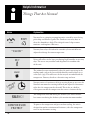
Noise Explanation
3-Minute
Delay
You may hear a pinging or popping noise caused by water being
picked up and thrown against the condenser on rainy days or
when the humidity is high. This design feature helps remove
moisture and improve efficiency.
You may hear relays click when the controls cycle on and off or are
adjusted to change the room temperature.
Water will collect in the base pan during high humidity or on rainy
days. The water may overflow and drip from the outdoor side
of the unit.
The indoor fan runs continuously when the unit is operating in the
cooling mode, unless the fan switch behind the room cabinet is set
at fan cycle (up). This will cause the fan to cycle on and off with the
compressor. You may also hear a fan noise stop and start.
You may notice a few minutes delay in starting if you try to restart the
Zoneline too soon after turning it off or if you adjust the thermostat
right after the compressor has shut off. This is due to a built-in
restart protector for the compressor that causes a 3-minute delay.
The compressor shuts off during the defrost cycle. Full resistance
heat comes on during the defrost cycle to maintain room comfort.
To protect the compressor and prevent short cycling, the unit is
designed to run for a minimum of 3 minutes, after the compressor
starts at any thermostat setting.
P
I
N
G
!
POP!
“CLICK”
D R I P
WHIR!
SILENCE
COMPRESSOR
PROTECT
Helpful Information
Things That Are Normal
Page is loading ...
Page is loading ...
Page is loading ...
Page is loading ...
-
 1
1
-
 2
2
-
 3
3
-
 4
4
-
 5
5
-
 6
6
-
 7
7
-
 8
8
-
 9
9
-
 10
10
-
 11
11
-
 12
12
-
 13
13
-
 14
14
-
 15
15
-
 16
16
-
 17
17
-
 18
18
-
 19
19
-
 20
20
-
 21
21
-
 22
22
-
 23
23
-
 24
24


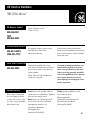
GE AZ52H12DAB User manual
- Category
- Split-system air conditioners
- Type
- User manual
Ask a question and I''ll find the answer in the document
Finding information in a document is now easier with AI
Related papers
Other documents
-
 GE Monogram 3900 series User manual
-
GE Zoneline AZ45E09DAP User guide
-
Amana PTAC FUSE HOLDER KIT (FHK) Installation guide
-
GEAppliances AZ75H09DAC Technical Service Manual
-
 First America PTACSWITCHA Installation guide
-
Legrand Chan-L-Wire Pro Series System Fan Tap Kit Installation guide
-
 Envi High-Efficiency Whole Room 120v Plug-In Electric Panel Wall Heater - 2nd Generation User manual
-
Vent-Axia sentinel Kinetic MVHR series User Instructions


