

www.netcomm.com.au Rev. 1 - YML668
Page 2 NP5400 11g Wireless Access Point User Guide
Contents
Chapter 1: Introduction .................................................................................................. 3
The NetComm 11G 54Mbps Wireless Access Point...................................... 3
Chapter 2: Planning Your Wireless Network ................................................................ 4
Network Topology ............................................................................................ 4
Roaming .......................................................................................................... 4
How to Make Your Wireless Network More Secure ......................................... 5
Chapter 3: Your NetComm 11G Wireless AP ............................................................... 6
The Back Panel................................................................................................ 6
The Front Panel ............................................................................................... 7
Chapter 4: Connecting the Wireless AP ....................................................................... 8
Package Contents ........................................................................................... 8
Hardware Installation ...................................................................................... 8
Chapter 5: Setting Up the Wireless Access Point ...................................................... 10
Connecting the AP to your Network ............................................................... 10
Setting Up TCP/IP in Windows ...................................................................... 10
Installing the Wireless Navigator .................................................................. 13
Startup and Login .......................................................................................... 14
Configuring the Access Point ........................................................................ 15
Firmware Upgrade Procedure....................................................................... 22
Appendix A: Troubleshooting ...................................................................................... 23
Frequently Asked Questions ......................................................................... 23
Appendix B: Glossary .................................................................................................. 26
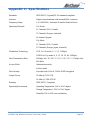
Appendix C: Specifications.......................................................................................... 31
Registering your NetComm Product........................................................................... 32
Trademarks and Notices ............................................................................................ 32
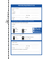
Warranty Registration Form .......................................................................... 33
Product Warranty............................................................................................ 35
Limitations of Warranty .................................................................................. 35

Rev. 1 - YML668 www.netcomm.com.au
NP5400 11g Wireless Access Point User Guide Page 3
Chapter 1: Introduction
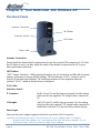
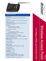
The NetComm 11G 54Mbps Wireless Access Point
Congratulations on your purchase of the Netcomm 11G 54Mbps Wireless Access Point (AP).
This product is designed specifically for high-speed wireless LAN environment needs. It is easy
to configure and operate even for non-technical users. Instructions for installing and configuring
this product are included in this manual. Before you install and use this product, please read the
manual carefully so you may take full advantage of its functions.
■ 11g Draft Standards Compliant - The AP complies with IEEE802.11g standard, and it is
interoperable with IEEE802.11g-Compliant Equipment.
■ Interoperable with IEEE802.11b -Backward compatible with IEEE802.11b equipment.
■ Flexible Connectivity - Using external, detachable dipole antenna allows connection of
optional Directional Antenna.
■ Data Rate Auto Fall-Back - Provides 54, 48, 36, 24,12, 11, 9, 6, 5.5, 2 and 1Mbps wireless
data rate shifting dynamically between 11g and 11b to guarantee availability and reliability of
wireless connections.
■ Roaming - Provides seamless roaming within 802.11g and 802.11b wireless LAN
infrastructure.
LAN Features
■ Built-in 10/100M LAN Port - It's designed to connect the AP with any 10/100M LAN Hub/
Switch or router.
■ DHCP Client - Enable the AP to act as a DHCP client to receive IP address from DHCP
Server in the wired Ethernet LAN.
Configuration & Management
■ Easy to Setup - With windows-based Wireless Navigator Utility, user can easily setup the
IP address of this AP, and upgrade the firmware.
■ Easy to manage - User can use any WEB browser from anywhere on the wired or wireless
LAN to configure the AP easily.
Security
■ Configuring Protection - Provides password protection to prevent unauthorized users from
changing the configuration
■ Wireless LAN Security - Provide 64-bit & 128-bit Wired Equivalent Privacy encryption to
protect the wireless data transmissions.

www.netcomm.com.au Rev. 1 - YML668
Page 4 NP5400 11g Wireless Access Point User Guide
Chapter 2: Planning Your Wireless Network
Network Topology
A wireless LAN is a group of computers, each equipped with one Instant Wireless Series
adapter. Computers in a wireless LAN must be configured to share the same radio channel.
The Instant Wireless Series adapters provide access to a wired LAN for wireless workstations.
An integrated wireless and wired LAN is called an infrastructure configuration. A group of
Instant Wireless Series adapter users and an Instant Wireless 11g Wireless Access Point
compose a Basic Service Set (BSS). Each Instant Wireless Series adapter PC in a BSS can talk to
any computer in a wired LAN infrastructure via the 11g Wireless Access Point.
An infrastructure configuration extends the accessibility of an Instant Wireless Series adapter PC
to a wired LAN, and doubles the effective wireless transmission range for two Instant Wireless
Series adapter PCs. Since the 11g Wireless Access Point is able to forward data within its BSS,
the effective transmission range in an infrastructure LAN is doubled.
Roaming
Infrastructure mode also supports roaming capabilities for mobile users. More than one BSS can
be configured as an Extended Service Set (ESS). This continuous network allows users to roam
freely within an ESS. All PCs equipped with an Instant Wireless Series adapter within one ESS
must be configured with the same ESS ID and use the same radio channel.
Before enabling an ESS with roaming capability, choosing a feasible radio channel and optimum
11g Wireless Access Point position is recommended. Proper Access Point positioning combined
with a clear radio signal will greatly enhance performance.

Rev. 1 - YML668 www.netcomm.com.au
NP5400 11g Wireless Access Point User Guide Page 5
How to Make Your Wireless Network More Secure
Wireless networks can be vulnerable to an outsider gaining access if the encryption
settings are not set adequately. Some of the default security settings on some wireless
hardware, and in Microsoft Windows, may allow access to your wireless network from
other wireless devices.
The concepts that are presented here are offered only as a guide, and may help make
your wireless network more difficult for an outsider to gain access. For more specific
information about the implementation of these suggestions, you should consult a
trusted security source.
■ Enable Wired Equivalent Privacy (WEP) encryption.
The 802.11 standard, which your NetComm WLAN device is based on, permits Wired
Equivalent Privacy (WEP) encryption. Depending on what other hardware you use, there are
two levels of WEP typically available: 64-bit encryption (based on a 40-bit encryption key),
and 128-bit encryption (based on a 104-bit key). We strongly recommend that you enable
WEP.
■ Change the default Service Set Identifier (SSID) and passwords for your network devices.
Do not change the SSID or password to reflect your name, address, or anything that would
be easy to guess as this could make it easy for an outsider to gain access to your wireless
network.
■ Install Access Points away from windows or building perimeter.
If you are installing access points, think about locating them towards the centre of your site
instead of near the windows. Plan your coverage to radiate out to the windows, but not
beyond. If the access points are located near the windows, a stronger signal will be radiated
outside your home making it easier for those outside the building to locate your network.
■ Check the range of your network.
Take a notebook, or a PDA computer, that is equipped with a wireless network PC Card and
go outside your home to survey what range you get when moving around your property or
neighbourhood. You may be surprised how far the signal radiates. If you can connect beyond
the perimeter of your property, so can someone else.
■ Disable the Beacon.
If possible, disabling the beacon will make it harder for hackers to locate and identify your
network.
■ Use a combination of the previous suggestions.

www.netcomm.com.au Rev. 1 - YML668
Page 6 NP5400 11g Wireless Access Point User Guide
Chapter 3: Your NetComm 11G Wireless AP
The Back Panel
Antenna Connection
Antenna Connection
Please install the external dipole antenna directly into the reversed SMA connector of AP. After
the AP starts to work, you may adjust the angle of the antenna or reposition the AP to get a
better performance and reach.
INIT Button
“INIT” means “Initiation”. While pressing the button, the AP will reboot and ERASE all current
settings, and restore to factory default settings. The left indicator “DIAG” on the AP will at
first be off and then begin blinking. The initiation procedure will be completed when the
indicator “DIAG” returns to being always on and green.
LAN Cable
Selection Switch
X Crossover: the RJ-45 port Tx and Rx lines are reversed. Use this setting
when you use the supplied UTP straight cable connected to
PC.
II Straight: the RJ-45 port Tx and Rx lines are normal. Use this setting
when you have the supplied UTP straight cable connected to
Hub/Switch or Router. It is also the factory default setting.
Power Input
Only use the power adapter supplied with the Access Point LAN Connection
Important: Resetting the Access Point will erase all of your settings (WEP Encryption,
Wireless and LAN settings, etc.) and replace them with the factory defaults. Do not
reset the Access Point if you want to retain these settings
INIT Button
Selection Switch
LAN Cable
Power Input

Rev. 1 - YML668 www.netcomm.com.au
NP5400 11g Wireless Access Point User Guide Page 7
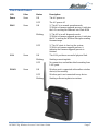
The Front Panel
LED Color Status Description
Power Green ON The AP power on
OFF The AP power off
DIAG Green ON 1) The AP is in normal operation mode
2) While in firmware upgrade process, it indicates
the AP is writing the firmware into Flash ROM
Blinking 1) The AP is in self-diagnostic mode.
2) While in firmware upgrade process, it indicates
the AP is waiting the Wireless Navigator sending
firmware image
OFF 1) The AP starts to boot up the system.
2) While in firmware upgrade process, it
indicates the firmware upgrade process is
finished.
LAN Green ON The LAN port has a successful physical link.
Blinking Sending or receiving data
OFF No connection, and neither data forwarding from
LAN ports.
WLAN Green ON Wireless port is connected with another wireless
device(s) successfully
OFF Wireless port is not connected to any device.
Blinking Sending or Receiving data via wireless

www.netcomm.com.au Rev. 1 - YML668
Page 8 NP5400 11g Wireless Access Point User Guide
Chapter 4: Connecting the Wireless AP
Before continuing, please ensure you have the following package contents ready for the
hardware installation.
Package Contents
■ One Wireless Access Point
■ One External Antenna with Reversed SMA Connector
■ One UTP straight LAN Cable (RJ-45 connector)
■ One Power Adapter
■ One CD-ROM (Wireless Navigator utility software & user’s manual included)
■ One User Guide
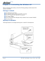
Hardware Installation
Following illustration is an example showing how to install AP with hub/switch.

Rev. 1 - YML668 www.netcomm.com.au
NP5400 11g Wireless Access Point User Guide Page 9
1. Find an optimum location for the Access Point. The best place for the Access Point is
usually at the center of your wireless network, with line of sight to all of your mobile
stations. Placing the unit in the celing is ideal.
2. Fix the direction of the antenna. Try to place it in a position which can best cover your
wireless network. Normally, the higher you place the antenna, the better the performance
will be. The antenna's position enhances the receiving sensitivity.
3. Connect a standard Ethernet network cable to the Access Point. Then, connect the other end
of the Ethernet cable to a switch or hub. The Access Point will then be connected to your
wired Network.
4. Connect the AC Power Adapter to the Access Point's Power port and plug the other end
into an electrical outlet. Only use the power adapter supplied with the Access Point. Use of
a different adapter may result in product damage.
Now that the hardware installation is complete, proceed to Chapter 5: Setting Up the 11g
Wireless Access Point for directions on how to set up the Access Point.
Note: In order for all other wireless devices to communicate with the Access Point, those
devices must be operating in Infrastructure Mode. If any wireless devices are
configured in Ad Hoc Mode, they will not be recognized by the Access Point.

www.netcomm.com.au Rev. 1 - YML668
Page 10 NP5400 11g Wireless Access Point User Guide
Chapter 5: Setting Up the Wireless Access Point
Connecting the AP to your Network
For optimal performance, usually the center of your wireless network is the best place for your
AP, with line of sight to all of your mobile stations. Try to place it in a position where can best
cover your wireless network and is away from any potential source of interference. And
normally, the higher you place the AP, the better the wireless signal coverage will be.
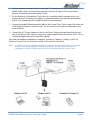
The following picture describes how to use the AP when communicating between wireless LAN
and wired LAN.
Setting Up TCP/IP in Windows
Before a computer can communicate with the Access Point, it must be configured with the TCP/
IP protocol. If you know how to set up TCP/IP on your computers, do so now. Otherwise, use
the guidelines below to help get TCP/IP installed on all of the computers that need to
communicate with the Access Point. If you are unable to successfully install TCP/IP on one or
more computers after following the directions, contact the manufacturer of your computers'
network operating system for further assistance. Check with your network administrator for
your TCP/IP settings.
The directions below provide general guidelines for coming up with IP addresses and subnet
masks. Check with your network administrator to see if you need to use specific IP addresses or
DHCP settings.
First, each computer on the network will require an IP address, which is a series of numbers,
separated by periods, identifying the PC on the network. To make things simple, you should use
the following numbering scheme:
192.168.1.X
In this example, X is a unique, arbitrarily assigned number from 1 to 254. Each computer must
have its own unique X number. Note: Never use 0, 250 or 255 for X. These numbers are
reserved by TCP/IP for other uses.
Each computer will also require a subnet mask, which is a numerical "filter" that tells a computer
what kinds of TCP/IP data packets to accept. If you're not sure which mask to use, the
following mask is recommended:
255.255.255.0
The following instructions are provided as examples for reference only. For complete
instructions on installing and troubleshooting TCP/IP please consult your Windows operating
system documentation.

Rev. 1 - YML668 www.netcomm.com.au
NP5400 11g Wireless Access Point User Guide Page 11
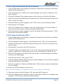
TCP/IP Setup for Windows 98 and Millennium
1. Click the Start button, select Settings, and open the Control Panel. Inside the Control Panel,
double-click the Network icon.
2. If the TCP/IP Protocol is listed for your network adapter, go to step five. Otherwise, click
the Add button.
3. When the Component Type window appears, select Protocol and click the Add button.
4. Select Microsoft in the Manufacturers list and choose TCP/IP in the Network Protocols list.
Then, click the OK button.
5. When the Network window reappears, click TCP/IP. Then, click the Properties button.
6. Select Specify an IP Address.
7. Enter an IP Address for the computer, along with a Subnet Mask. Click the OK button. If
you do not have these values, consult your network administrator.
8. When the Network window reappears, click the OK button. Restart your machine. TCP/IP
has now been successfully installed.
TCP/IP Setup for Windows NT4.0
1. Click the Start button, select Settings, and open the Control Panel. Inside the Control Panel,
double-click the Network icon.
2. When the Network window appears, click the Protocols tab. Then, click the Add button.
3. Find the TCP/IP protocol in the Select Network Protocol field. Click it once and then click
the OK button.
4. When asked if you want to use DHCP, choose No.
5. If asked to supply your Windows NT CD, do so. NT will copy the necessary files to your
system. You may have to switch between the Access Point's Setup CD and the NT CD.
6. When TCP/IP appears in the Network Protocols window, click the Bindings tab. Windows
will store your new bindings.
7. Click the Protocols tab. Then, select TCP/IP.
8. Click the Properties button. Select the type of network adapter you have from the Adapters
box and select Specify an IP Address.
9. Enter the computer's IP Address and Subnet Mask. Check with your network administrator
for your settings.
10. Enter your Default Gateway if you have one.
Note: a Default Gateway is not required. Check with your network administrator.
11. When you finish, click the OK button. If NT asks about WINS, ignore it.
12. When the Network window reappears, click the Close button. Restart your computer when
prompted. TCP/IP has now been successfully installed.

www.netcomm.com.au Rev. 1 - YML668
Page 12 NP5400 11g Wireless Access Point User Guide
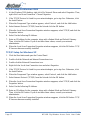
TCP/IP Setup for Windows 2000
1. At the Windows 2000 desktop, right click My Network Places and select Properties. Then,
right click Local Area Connection. Choose Properties.
2. If the TCP/IP Protocol is listed for your network adapter, go to step five. Otherwise, click
the Install button.
3. When the Component Type window appears, select Protocol, and click the Add button.
4. Select Internet Protocol (TCP/IP) from the list and click the OK button.
5. When the Local Area Connection Properties window reappears, select TCP/IP, and click the
Properties button.
6. Select Use the following IP Address.
7. Enter an IP Address for the computer, along with a Subnet Mask and Default Gateway.
Then, click the OK button. If you do not have these values, consult your network
administrator.
8. When the Local Area Connection Properties window reappears, click the OK button. TCP/
IP has now been successfully installed.
TCP/IP Setup for Windows XP
1. Click the Start button and open the Control Panel.
2. Double click the Network and Internet Connections icon.
3. Double click the Network Connections icon.
4. Right click the Local Area Connection icon and select Properties.
5. If the TCP/IP Protocol is listed for your network adapter, go to step five. Otherwise, click
the Install button.
6. When the Component Type window appears, select Protocol, and click the Add button.
7. Select Internet Protocol (TCP/IP) from the list and click the OK button.
8. When the Local Area Connection Properties window reappears, select TCP/IP, and click the
Properties button.
9. Select Use the following IP Address.
10. Enter an IP Address for the computer, along with a Subnet Mask and Default Gateway.
Then, click the OK button. If you do not have these values, consult your network
administrator.
11. When the Local Area Connection Properties window reappears, click the OK button. TCP/
IP has now been successfully installed.

Rev. 1 - YML668 www.netcomm.com.au
NP5400 11g Wireless Access Point User Guide Page 13
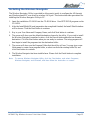
Installing the Wireless Navigator
The Wireless Navigator Utility is provided to allow user(s) easily to configure the AP through
any Windows-based PC over wired or wireless LAN port. This section describes procedures for
installing the Wireless Navigator Utility to PC.
1. Insert the installation CD-ROM into the CD-ROM drive. Run SETUP.EXE program on the
CD-ROM.
2. After the InstallShield Wizard preparation has completed finished, the Install Shield window
will be shown. Click the Next button to continue.
3. Key in your User Name and Company Name, and click Next button to continue.
4. The screen will show you the default destination chosen by the utility. If you wish to install
the Wireless Navigator in another location, click the Browse button and select an alternate
destination. Click the Next button when you are ready to continue. The setup program will
then begin to install the programs into the destination folder.
5. The screen will show you the Program Folder that the utility will use. You may type a new
folder name to create a new program folder, or select one from the existing folder list, and
click Next button to continue.
6. The Wireless Navigator has been installed now. Please click the Finish button to complete
installation.
Note: To remove Wireless Navigator Utility, click the Start button, and select Programs,
Wireless Navigator, and Uninstall, and then follow the instruction on screen.

www.netcomm.com.au Rev. 1 - YML668
Page 14 NP5400 11g Wireless Access Point User Guide
Startup and Login
Follow the procedures below to startup Wireless Navigator and find the AP. Before you start
the following procedure, please connect the Ethernet cable, connect the power cord, and then
turn on the AP. All wireless clients should be requested to set the their SSIDs to the same as the
AP SSID in advance before continuing.
1. Refer to previous section "Install the Wireless Navigator to your PC" in order to startup the
configuration.
2. Click Start and select Programs, Wireless Navigator and then Wireless Navigator. Or, just
double-click the Wireless Navigator icon on your desktop screen.
3. The Wireless Navigator starts up, and searches AP via wired LAN or Wireless LAN.
4. The utility will show the AP and any other wireless devices found in the same network.
Note! If the AP is not shown in the list, please make sure all the cables are well
connected.
5. Double-click on the AP device to access the built-in web server. The User Name and
Password screen will be displayed. The default setting is no user name and the password is
"admin". Click OK to continue.
Note! If you cannot access into AP's built-in web server, please make sure if your PC now
is in the same subnet with AP. Please us right-click of mouse to click on the AP
listed in Wireless Navigator. "Set IP address" option will pop out, and then change
IP address of AP to the same subnet as your PC.
6. Now you have entered the built-in web server of this AP, you can begin configuration
procedures.

Rev. 1 - YML668 www.netcomm.com.au
NP5400 11g Wireless Access Point User Guide Page 15
Configuring the Access Point
The Wireless Navigator includes nine tabs to help you customise your Access Point settings to
fit your Network:
■ the Info tab
■ the Assoc tab
■ the Wireless tab
■ the Access tab
■ the Advanced tab
■ the Security tab
■ the IP Address tab
■ the Admin tab
■ the Help tab

www.netcomm.com.au Rev. 1 - YML668
Page 16 NP5400 11g Wireless Access Point User Guide
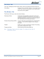
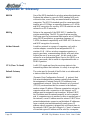
The Info Tab
The Info Tab displays the current AP settings.
Access Point Information
Access point name: Displays current device name of the AP. You also can change
the name.
MAC address of AP: Displays the unique fMAC number burned into this AP that
identifies itself from other Ethernet devices
Associated stations: Displays the number of wireless client devices associated
with this AP.
Wireless Firmware version: Displays the version number of wireless LAN firmware
embedded in this AP.
AP version: Displays the version number of AP system firmware.
Current IP settingsIP address: Displays the current IP address of this AP.
DHCP client: Displays if this AP enable DHCP client feature or not.
Current Wireless
SettingsPerformance Mode: Displays the AP is set in Maximum interoperability mode or
Maximum performance mode.
Wireless network name (SSID): Displays current SSID of the AP. Please make sure that
your wireless LAN is working properly under the effective
reach range of the AP
WEP: Displays the WEP function is enabled or disabled.

Rev. 1 - YML668 www.netcomm.com.au
NP5400 11g Wireless Access Point User Guide Page 17
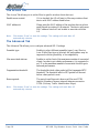
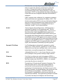
The Assoc Tab
The Assoc Tab displays all the wireless clients, which are currently associated with this AP.
Mac address: Displays the list of the MAC address of associated wireless
client.If you click the refresh button of your web browser,
then the list will be updated.
The Wireless Tab
The Wireless Tab lets you select the network settings.
Performance Mode: In Maximum interoperability mode, the AP will accept
connections to both 802.11b and 802.11g client devices. In
Maximum performance mode, the AP will only connect to
802.11g client devices for better performance.
Wireless Network Name (SSID): Lets you set the Service Set Identification. Default SSID is
"wireless". This should be changed to some thing non-
descriptive.
Channel: Enables you to select a transmission channel. This setting
only works in infrastructure mode.
Transmission Rate: Select transfer rate from an available list.
Note: Click button "Save" to store the settings. The settings will work after AP
automatically reboots.

www.netcomm.com.au Rev. 1 - YML668
Page 18 NP5400 11g Wireless Access Point User Guide
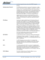
The Access Tab
The Access Tab allows you to set the filter to specific wireless client device(s).
Enable access control: If it is checked, the AP will start to filter any wireless client
device with MAC address listed below.
MAC address #: Please enter the MAC address of the wireless devices which
need filtered in wireless LAN network. The device with same
MAC address listed will not be able to associate with this
AP.
Note: Click button "Save" to store the settings. The settings will work after AP
automatically reboots.
The Advanced Tab
The Advanced Tab allows you to configure advanced 802.11 settings
Preamble type: Enables to select different preamble types: Long, Short or
Auto. While Short type is selected, the performance may be
improved with the possibility of incompatibility
Max associated stations: Enables to set the limit of the maximum number of associated
clients. In order to get a better performance, it is suggested to
set "8" as the maximum number of associated clients to get a
balanced performance
Fragmentation threshold: The threshold which a data packet will be fragmented.RTS
threshold: The threshold which a RTS packet will be sent
before a data packet is sent.
Beacon period: The period in millisecond a beacon will be sent.DTIM
interval: Number of beacon intervals between successive
DTIM (Delivery Traffic Identification Maps).
Note: Click button "Save" to store the settings. The settings will work after AP
automatically reboots.

Rev. 1 - YML668 www.netcomm.com.au
NP5400 11g Wireless Access Point User Guide Page 19
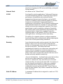
The Security Tab
The Security Tab displays 802.11b/g security and encryption options on this AP.
WEP configuration: Display the Wired Equivalent Privacy security
configurations
Enable WEP: Enables the Wired Equivalent Privacy security function.
WEP key length: Selects 64-bit or 128-bit WEP encryption. Be sure that the
key length setting in the AP shall be the same as in wireless
clients, or the communication will not work.
WEP key: For 64-bit WEP encryption, a key of 10 hexadecimal
characters in length must be filled in. For 128-bit WEP
encryption, a key of 26 hexadecimal characters in length
must be filled in. Be sure that the key values in the AP shall
be the same as in wireless clients, or the communication will
not work.
Default WEP key to use: Selects one of four key sets to be used for encryption. To
connect to a Wi-Fi compliant wireless device, key #1 must
be selected.
Deny unencrypted data: Check this box, then any unencrypted data frames will be
denied.
Authentication: Selects the mechanism of Open, Shared key, or both
authentication algorithms.
Firmware upgrading: To control firmware upgrade
Allow upgrade uploads: If the box is checked, then users can use utility or any TFTP
program to upgrade the firmware.
Note: Click button "Save" to store the settings. The settings will work after AP
automatically reboots.

www.netcomm.com.au Rev. 1 - YML668
Page 20 NP5400 11g Wireless Access Point User Guide
The IP Address Tab
The IP Address Tab displays IP settings options on this AP.
IP Address Mode: Select "Static" or "DHCP" mode. For "Static" mode, the IP
address settings are given by user. For "DHCP" mode, these
settings will be overridden by a DHCP server on your
network. The default setting is "Static"
Default IP Address: The static IP address you want to assign to the AP. The
default value is "192.168.1.100".
Default subnet mask: The subnet mask you want to assign for the AP. The default
value is "255.255.255.0".
Default gateway: The internet gateway you want to assign for the AP. The
default value is "192.168.1.1".
Access point name: With the name, the AP can be found easily via Wireless
Nevigator Utility. It can be the nickname assigned by the
adminstrator.
Note: Click button "Save" to store the settings. The settings will work after AP
automatically reboots.
Page is loading ...
Page is loading ...
Page is loading ...
Page is loading ...
Page is loading ...
Page is loading ...
Page is loading ...
Page is loading ...
Page is loading ...
Page is loading ...
Page is loading ...
Page is loading ...
Page is loading ...
Page is loading ...
Page is loading ...
Page is loading ...
-
 1
1
-
 2
2
-
 3
3
-
 4
4
-
 5
5
-
 6
6
-
 7
7
-
 8
8
-
 9
9
-
 10
10
-
 11
11
-
 12
12
-
 13
13
-
 14
14
-
 15
15
-
 16
16
-
 17
17
-
 18
18
-
 19
19
-
 20
20
-
 21
21
-
 22
22
-
 23
23
-
 24
24
-
 25
25
-
 26
26
-
 27
27
-
 28
28
-
 29
29
-
 30
30
-
 31
31
-
 32
32
-
 33
33
-
 34
34
-
 35
35
-
 36
36


Ask a question and I''ll find the answer in the document
Finding information in a document is now easier with AI
Related papers
Other documents
-
CNET CNAP-711 User manual
-
Draytek Vigor550 User manual
-
Abocom WUG2400 User manual
-
Universal Scientific Industrial AP-AG-AT-02 User manual
-
Digisol DG-WR3001NE (H/W Ver. A1) User manual
-
-
X-Micro XWL-11GPRG User manual
-
 X-Micro Tech. WLAN 11b Access Point User manual
-
NetComm Wireless NF18ACV Troubleshooting Manual
-
Hawking HWUR54G User manual
