Garmin Reactor40-Steer-by-Wire-Standard-Basispaket Installation guide

Type
Installation guide
REACTOR™ 40 STEER-BY-
WIRE
Installation Instructions
Important Safety Information
WARNING
See the Important Safety and Product Information guide in the
product box for product warnings and other important
information.
You are responsible for the safe and prudent operation of your
vessel. The autopilot is a tool that enhances your capability to
operate your boat. It does not relieve you of the responsibility of
safely operating your boat. Avoid navigational hazards and
never leave the helm unattended.
Always be prepared to promptly regain manual control of your
boat.
Learn to operate the autopilot on calm and hazard-free open
water.
Use caution when operating the autopilot near hazards in the
water, such as docks, pilings, and other boats.
CAUTION
When in use, beware of hot motor and solenoid components
and the risk of entrapment from moving parts.
Failure to install and maintain this equipment in accordance with
these instructions could result in damage or injury.
NOTICE
To avoid damage to your boat, the autopilot system should be
installed by a qualified marine installer. Specific knowledge of
hydraulic steering componentry and marine electrical systems is
required for proper installation.
Registering Your Device
Help us better support you by completing our online registration
today. Keep the original sales receipt, or a photocopy, in a safe
place.
1
Go to my.garmin.com/registration .
2
Sign in to your Garmin
®
account.
Installation Preparation
The autopilot system consists of multiple components. You
should familiarize yourself with all of the component mounting
and connection considerations before beginning installation. You
must know how the components operate together in order to
correctly plan the installation on your boat.
You can consult the layout diagrams (Power and Data Layout,
page 2) to help understand the mounting and connection
considerations.
You should lay out all of the components on the boat as you
plan the installation to make sure your cables will reach each
component. If needed, extension cables (sold separately) for
various components are available from your Garmin dealer or
from www.garmin.com.
You should record the serial number of each component for
registration and warranty purposes.
Tools Needed
Safety glasses
Drill and drill bits
90 mm (3.5 in.) hole saw or a rotary cutting tool (for installing
an optional helm control)
Wire cutters/strippers
Phillips and flat screwdrivers
Cable ties
Waterproof wire connectors (wire nuts) or heat-shrink tubing
and a heat gun
Marine sealant
Portable or handheld compass (to test for magnetic
interference)
NOTE: Mounting screws are provided for the main components
of the autopilot system. If the provided screws are not
appropriate for the mounting surface, you must provide the
correct types of screws.
Mounting and Connection Considerations
The autopilot components connect to each other and to power
using the included cables. Ensure that the correct cables reach
each component and that each component is in an acceptable
location before mounting or wiring any components.
CCU Mounting and Connection Considerations
The CCU is the primary sensor of the Reactor 40 Steer-by-
Wire autopilot system. For best performance, observe these
considerations when selecting a mounting location.
A handheld compass should be used to test for magnetic
interference in the area where the CCU is to be
mounted(Testing a Location for Magnetic Interference,
page 1).
The CCU should be mounted on a rigid surface for best
performance.
Mounting screws are provided with the CCU. If you use
mounting hardware other than the provided screws, the
hardware must be quality stainless or brass material to avoid
magnetic interference with the CCU.
Test any mounting hardware with a handheld compass to
make sure no magnetic fields are present in the hardware.
The CCU cable connects the CCU to the steering system and
is 3 m (9 ft.) long.
If the CCU cannot be mounted within 3 m (9 ft.) of the
steering system, extension cables are available from your
local Garmin dealer or at www.garmin.com.
This cable must not be cut.
Finding the Best Mounting Location
1
Create a list of all suitable mounting locations for the CCU.
Suitable mounting locations should not be within 60 cm (2 ft.)
of the following:
Iron
Magnets
High-current wires
Intermittently-running pumps, such as head pumps and
live well pumps
A large magnet, such as a subwoofer-speaker magnet,
should be no closer than 1.5 m (5 ft.) to any of the mounting
locations.
2
Locate the center of rotation of the boat, and measure the
distance between the center of rotation and each of the
suitable mounting locations you listed in step 1.
3
Select the location closest to the center of rotation.
If more than one location is approximately the same distance
from the center of rotation, you should select the location that
best meets these considerations.
The best location is closest to the centerline of the boat.
The best location is lower in the boat.
The best location is slightly forward in the boat.
Testing a Location for Magnetic Interference
You can use a handheld compass to test a mounting location for
magnetic interference.
October 2017
190-02318-02_0A
1
Hold a handheld compass in the CCU mounting location.
2
Move the compass six inches to the left of the location, then
six inches to the right, observe the needle, and select an
action:
If the compass needle moves more than three degrees
during this step, magnetic interference is present. Select a
new mounting location and repeat the test.
If the compass needle does not move, or moves less than
three degrees, proceed to the next step.
3
Repeat this process while moving the compass above and
below the mounting location.
4
Repeat this process while moving the compass in front of and
behind the mounting location.
Alarm Mounting and Connection Considerations
The alarm should be mounted near the primary helm station.
The alarm can be mounted under the dashboard.
If needed, the alarm wires can be extended with 28 AWG
(0.08 mm
2
) wire.
NMEA 2000
®
Connection Considerations
The CCU and the helm control must connect to a NMEA
2000 network.
If your boat does not already have a NMEA 2000 network,
one can be built using the included NMEA 2000 cables and
connectors (Building a Basic NMEA 2000 Network for the
Autopilot System, page 3).
To use the advanced features of the autopilot, optional
NMEA 2000 devices, such as a wind sensor, a water-speed
sensor, or a GPS device, can be connected to the NMEA
2000 network.
Power and Data Layout
WARNING
When connecting the power cable, do not remove the in-line
fuse holder. To prevent the possibility of injury or product
damage caused by fire or overheating, the appropriate fuse
must be in place as indicated in the product specifications. In
addition, connecting the power cable without the appropriate
fuse in place voids the product warranty.
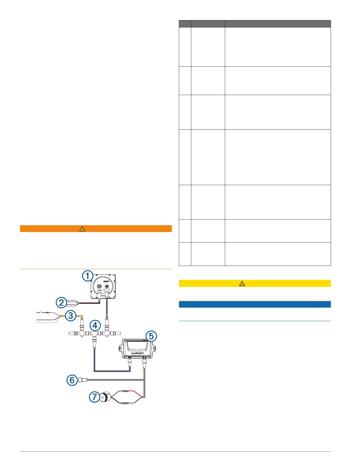
Item Description Important Considerations
À
Helm control A dedicated helm control is not included in all
autopilot packages. If you install the autopilot
without a dedicated helm control, the autopilot
CCU must be connected to the same NMEA
2000 network as a compatible Garmin
chartplotter to configure and control the autopilot
system.
Á
Helm control
data cable
You should install this cable only if you are
connecting the autopilot to optional NMEA
®
0183
devices, such as a wind sensor, a water-speed
sensor, or a GPS device (NMEA 0183
Connection Considerations, page 4).
Â
NMEA 2000
power cable
You should install this cable only if you are
building a NMEA 2000 network. Do not install this
cable if there is an existing NMEA 2000 network
on your boat.
You must connect the NMEA 2000 power cable
to a 9 to 16 Vdc power source.
Ã
NMEA 2000
network
You must connect the helm control or compatible
Garmin chartplotter and the CCU to a NMEA
2000 network using the included T-
connectorsNMEA 2000
®
Connection
Considerations, page 2.
If there is not an existing NMEA 2000 network on
your boat, you can build one using the supplied
cables and connectors (Building a Basic NMEA
2000 Network for the Autopilot System,
page 3).
Ä
CCU You can mount the CCU in a non-submerged
location near the center of the boat, in any
orientation (CCU Mounting and Connection
Considerations, page 1).
Mount the CCU away from sources of magnetic
interference.
Å
Engine
connection
The CCU connects to the engine control either
directly or through an adapter. Additional
instructions are provided with the adapter, if
applicable.
Æ
Alarm The alarm provides audible alerts from the
autopilot system, and you should install it near
the primary helm station (Installing the Alarm,
page 3).
Installation Procedures
CAUTION
Always wear safety goggles, ear protection, and a dust mask
when drilling, cutting, or sanding.
NOTICE
When drilling or cutting, always check what is on the opposite
side of the surface.
After you have planned the autopilot installation on your boat
and satisfied all of the mounting and wiring considerations for
your particular installation, you can begin mounting and
connecting the components.
Helm Control Installation
A dedicated helm control is not included in all autopilot
packages. If you install the autopilot without a dedicated helm
control, the autopilot CCU must be connected to the same
NMEA 2000 network as a compatible Garmin chartplotter to
configure and control the autopilot system.
Detailed mounting instructions are included in the helm control
box.
Mounting the CCU
1
Determine the mounting location.
2
Using the CCU as a template, mark the two pilot hole
locations on the mounting surface.
3
Using a 3 mm (
1
/
8
in.) bit, drill the pilot holes.
2
4
Use the included screws to attach the CCU to the mounting
surface.
NOTE: If you use mounting hardware other than the provided
screws, the hardware must be quality stainless or brass
material to avoid magnetic interference with the CCU.
Test any mounting hardware with a handheld compass to
make sure no magnetic fields are present in the hardware.
Connecting the CCU
1
Route the connector end of the CCU cable to the steering
system connection or CAN bus and make the connection.
2
Route the orange and blue wires from the bare-wire portion
of the CCU cable to the location where you plan to install the
alarm (Installing the Alarm, page 3).
If the cable is not long enough, extend the appropriate wires
with 0.08 mm
2
(28 AWG) wire.
Connecting to the Steering System of the Boat
NOTICE
Do not connect the steering controller cable to a NMEA 2000
network.
The autopilot requires a powered CAN bus to communicate with
the steering controller. Ensure the steering controller CAN bus is
properly powered and terminated. Consult the boat
manufacturer if needed.
The steering controller cable allows the autopilot system to
communicate with the steering system of the boat through a
steering controller CAN bus. Additional instructions are supplied
with the CAN bus.
If needed, consult the manufacturer of your boat for assistance
locating the steering-system access.
1
Locate the steering-system access for your boat.
2
Connect the steering controller cable from the CCU to the
steering system through the included steering controller CAN
bus.
NOTE: If necessary, the steering controller cable can be
extended using a NMEA 2000 extension cable.
Installing the Alarm
Before you can mount the alarm, you must select a mounting
location (Alarm Mounting and Connection Considerations,
page 2).
1
Route the alarm cable to the bare-wire end of the CCU cable.
If the cable is not long enough, extend the appropriate wires
with 28 AWG (0.08 mm
2
) wire.
2
Connect the cables, based on this table.
Alarm Wire Color CCU Cable Wire Color
White (+) Orange (+)
Black (-) Blue (-)
3
Solder and cover all bare-wire connections.
4
Secure the alarm with cable ties or other mounting hardware
(not included).
NMEA 2000 and the Autopilot Components
A dedicated helm control is not included in all autopilot
packages. If you install the autopilot without a dedicated helm
control, the autopilot CCU must be connected to the same
NMEA 2000 network as a compatible Garmin chartplotter to
configure and control the autopilot system.
NOTICE
If you are connecting this device to an existing NMEA 2000
network, the NMEA 2000 network should already be connected
to power. Do not connect the NMEA 2000 power cable to an
existing NMEA 2000 network, because only one power source
should be connected to a NMEA 2000 network.
If you are connecting this device to an existing NMEA 2000
network or engine network by another manufacturer, you should
install a NMEA 2000 Power Isolator (010-11580-00) between
the existing network and the Garmin devices.
You can connect the CCU and the optional helm control through
an existing NMEA 2000 network. If you do not have an existing
NMEA 2000 network on your boat, all the parts needed to build
one are supplied in the autopilot package (Building a Basic
NMEA 2000 Network for the Autopilot System, page 3).
To use the advanced features of the autopilot, optional NMEA
2000 devices, such as a GPS device, can be connected to the
NMEA 2000 network.
If you are unfamiliar with NMEA 2000, you should read the
“NMEA 2000 Network Fundamentals” chapter of the Technical
Reference for NMEA 2000 Products. To download this
document, select Manuals on the product page for your device
at www.garmin.com.
Building a Basic NMEA 2000 Network for the Autopilot
System
NOTICE
If you are installing a NMEA 2000 power cable, you must
connect it to the boat ignition switch or through another in-line
switch. NMEA 2000 devices will drain your battery if the NMEA
2000 power cable is connected to the battery directly.
A dedicated helm control is not included in all autopilot
packages. If you install the autopilot without a dedicated helm
control, the autopilot CCU must be connected to the same
NMEA 2000 network as a compatible Garmin chartplotter to
configure and control the autopilot system.
1
Connect the three T-connectors
À
together side-by-side.
2
Connect the included NMEA 2000 power cable
Á
to a 9 to
12 Vdc power source
Â
through a switch
Ã
.
You should connect the power cable to the ignition switch of
the boat if possible, or route it through an inline switch (not
included).
NOTE: The braided drain wire (bare) on the NMEA 2000
power cable must be connected to the same ground as the
black wire on the NMEA 2000 power cable.
3
Connect the NMEA 2000 power cable to one of the T-
connectors.
4
Connect one of the included NMEA 2000 drop cables
Ä
to
one of the T-connectors and to the helm control (optional) or
to a compatible Garmin chartplotter
Å
.
5
Connect the other included NMEA 2000 drop cable to the
other T-connector and to the CCU
Æ
.
6
Connect the male and female terminators
Ç
to each end of
the combined T-connectors.
3
Connecting the Autopilot Components to an Existing NMEA
2000 Network
A dedicated helm control is not included in all autopilot
packages. If you install the autopilot without a dedicated helm
control, the autopilot CCU must be connected to the same
NMEA 2000 network as a compatible Garmin chartplotter to
configure and control the autopilot system.
1
Determine where to connect the CCU
À
and the helm control
(optional)
Á
to your existing NMEA 2000 backbone
Â
.
2
In the location where you plan to connect the CCU,
disconnect one side of a NMEA 2000 T-connector
Ã
from the
network.
3
If necessary, connect a NMEA 2000 backbone extension
cable (not included) to the side of the disconnected T-
connector to extend the NMEA 2000 network backbone.
4
Add an included Tconnector for the CCU to the NMEA 2000
backbone by connecting it to the side of the disconnected
Tconnector or backbone extension cable.
5
Route the included drop cable
Ä
to the CCU and to the
bottom of the T-connector added in step 4.
If the included drop cable is not long enough, you can use a
drop cable up to 6 m (20 ft.) long (not included).
6
Connect the drop cable to the CCU and the T-connector.
7
If needed, repeat steps 2 through 6 for the helm control
(optional) or a compatible Garmin chartplotter.
Connecting Optional NMEA 2000 Devices to the
Autopilot System
You can use advanced features of the autopilot system by
connecting optional NMEA 2000 compatible devices, such as a
GPS device, to the NMEA 2000 network.
NOTE: You can connect optional devices that are not NMEA
2000 compatible to the helm control through NMEA 0183
(NMEA 0183 Connection Considerations, page 4).
1
Add an additional T-connector (not included) to the NMEA
2000 network.
2
Connect the optional NMEA 2000 device to the T-connector
by following the instructions provided with the device.
Configuration
The autopilot must be configured and tuned to your boat
dynamics. You can use the Dockside Wizard and the Sea Trial
Wizard on the helm control or a compatible Garmin chartplotter
to configure the autopilot.
See the included configuration guide for more information on
configuring the autopilot.
Appendix
NMEA 0183 Connection Diagrams
The helm control is not included in all autopilot packages. A
helm control must be installed in your autopilot system to
connect NMEA 0183 devices according to these diagrams. If
you install the autopilot without a helm control, all NMEA devices
you plan to use with the autopilot system must be connected to
a compatible Garmin chartplotter on the same NMEA 2000
network as the CCU. See the installation instructions provided
with your chartplotter for NMEA 0183 connection information.
These wiring diagrams are examples of different situations you
may encounter when connecting your NMEA 0183 device to the
helm control.
NMEA 0183 Connection Considerations
There is one internal NMEA 0183 input port (RX port) and
one internal NMEA 0183 output port (TX port) on the included
NMEA 0183 data cable. You can connect one NMEA 0183
device to the internal RX port to input data to this Garmin
device, and you can connect up to three NMEA 0183 devices
in parallel to the internal TX port to receive data output by this
Garmin device.
See the installation instructions for the NMEA 0183 device to
identify the transmit (TX) and receive (RX) wires.
The device provides one TX port and one RX port. Each
internal port has 2 wires, labeled A and B according to the
NMEA 0183 convention. The corresponding A and B wires of
each internal port should be connected to the A (+) and B (-)
wires of the NMEA 0183 device.
You must use 28 AWG, shielded, twisted-pair wiring for
extended runs of wire. Solder all connections and seal them
with heat-shrink tubing.
Do not connect the NMEA 0183 data wires from this device
to power ground.
The power cable from this device and the NMEA 0183
devices must be connected to a common power ground.
For two-way communication with a NMEA 0183 device, the
internal ports on the NMEA 0183 data cable are not linked.
For example, if the input of the NMEA 0183 device is
connected to TXA on the data cable, you can connect the
output port of your NMEA 0183 device to the input port on the
wiring harness.
See Specifications, page 5 for a list of the approved NMEA
0183 sentences that are output by and input to this device.
The internal NMEA 0183 ports and communication protocols
are configured on the connected Garmin device. See the
NMEA 0183 section of the chartplotter owner's manual for
more information.
Two-Way NMEA 0183 Communication
4
À
NMEA 2000 network (provides power to the helm control)
Á
12 Vdc power source
Â
Helm control
Ã
NMEA 0183 compatible device
Wire Helm Control Wire Color —
Function
NMEA 0183 Compatible
Device Wire Function
Ê
N/A Power
Ë
N/A NMEA 0183 ground
Ì
Blue — Tx/A (+) Rx/A (+)
Í
White — Tx/B (-) Rx/B (-)
Î
Brown — Rx/A (+) Tx/A (+)
Ï
Green — Rx/B (-) Tx/B (-)
NOTE: When connecting a NMEA 0183 device with two
transmitting and two receiving lines, you do not need to connect
the NMEA 2000 bus and the NMEA 0183 device to a common
ground.
Only One Receiving Wire
If your NMEA 0183 compatible device has only one receiving
wire (Rx), you must connect it to the blue wire (Tx/A) from the
helm control, and leave the white wire (Tx/B) from the helm
control unconnected.
À
NMEA 2000 network (provides power to the helm control)
Á
12 Vdc power source
Â
Helm control
Ã
NMEA 0183 compatible device
Wire Helm Control Wire Color —
Function
NMEA 0183 Compatible
Device Wire Function
Ê
N/A Power
Ë
N/A NMEA 0183 ground
Ì
Blue — Tx/A (+) Rx
Í
White — unconnected N/A
Î
Brown — Rx/A (+) Tx/A (+)
Ï
Green — Rx/B (-) Tx/B (-)
NOTE: When connecting a NMEA 0183 device with only one
receiving (Rx) line, you must connect the NMEA 2000 bus and
the NMEA 0183 device to a common ground.
Only One Transmitting Wire
If your NMEA 0183 compatible device has only one transmitting
wire (Tx), it must be connected to the brown wire (Rx/A) from the
helm control, and the green wire (Rx/B) from the helm control
must be connected to NMEA 0183 ground.
À
NMEA 2000 network (provides power to the helm control)
Á
12 Vdc power source
Â
Helm control
Ã
NMEA 0183-compatible device
Wire Helm Control Wire Color —
Function
NMEA 0183 Compatible
Device Wire Function
Ê
N/A Power
Ë
Green — Rx/B (-) (connect to
NMEA 0183 ground)
NMEA 0183 ground
Ì
Blue — Tx/A (+) Rx/A (+)
Í
White — Tx/B (-) Rx/B (-)
Î
Brown — Rx/A (+) Tx/A (+)
NOTE: When connecting a NMEA 0183 device with only one
transmitting (Tx) line, you must connect the NMEA 2000 bus
and the NMEA 0183 device to a common ground.
Specifications
CCU
Specification Measurement
Dimensions (L × W × H) 170 × 90 × 50 mm (6.7 × 3.5 × 2 in.)
Weight 200 g (7 oz.)
Temperature range From -15° to 70°C (from 5° to 158°F)
Material Fully gasketed, high-impact plastic
Water resistance IEC 60529 IPX7*
CCU cable length 3 m (9 ft.)
NMEA 2000 input voltage From 9 to 16 Vdc
NMEA 2000 LEN 4 (200 mA)
*The device withstands incidental exposure to water of up to 1 m for up
to 30 min. For more information, go to www.garmin.com/waterrating.
Alarm
Specification Measurement
Dimensions (L×diameter)
29
/
32
× 1 in. (23 × 25 mm)
Weight 2.4 oz. (68 g)
Temperature range From 5°F to 140°F (from -15°C to 60°C)
Cable length 10 ft. (3.0 m)
NMEA 2000 PGN Information
CCU
Type PGN Description
Transmit and
receive
059392 ISO acknowledgment
059904 ISO request
060928 ISO address claim
126208 NMEA: Command/Request/Acknowledge
group function
5
Type PGN Description
126464 Transmit/Receive PGN list group function
126996 Product information
127257 Transmit/Receive attitude data
127251 Transmit/Receive rate of turn
Transmit only 127250 Vessel heading
Receive only 127258 Magnetic variation
127488 Engine parameters: Rapid update
128259 Water speed
129025 Position: Rapid update
129026 COG & SOG: Rapid update
129283 Cross track error
129284 Navigation data
130306 Wind data
Helm Control
Type PGN Description
Transmit and
receive
059392 ISO acknowledgment
059904 ISO request
060928 ISO address claim
126208 NMEA: Command/Request/Acknowledge
group function
126464 Transmit/Receive PGN list group function
126996 Product information
Transmit only 128259 Water speed
129025 Position: Rapid update
129026 COG & SOG: Rapid update
129283 Cross track error
129284 Navigation data
129540 GNSS satellites in view
130306 Wind data
Receive only 127245 Rudder data
127250 Vessel heading
127488 Engine parameters: Rapid update
128259 Water speed
129025 Position: Rapid update
129029 GNSS position data
129283 Cross-track error
129284 Navigation data
129285 Navigation: Route/Waypoint information
130306 Wind data
130576 Small craft status
NMEA 0183 Information
When connected to optional NMEA 0183 compatible devices,
the autopilot uses the following NMEA 0183 sentences.
Type Sentence
Transmit hdm
Receive wpl
gga
grme
gsa
gsv
rmc
bod
Type Sentence
bwc
dtm
gll
rmb
vhw
mwv
xte
Error and Warning Messages
Error Message Cause Autopilot Action
Autopilot is not
receiving
navigation data.
Autopilot placed in
Heading Hold.
The autopilot is no longer
receiving valid navigation
data while performing a
Route To maneuver.
This message also appears
if navigation is stopped on a
chartplotter before the
autopilot is disengaged.
Alarm sounds for
5 seconds
Autopilot
transitions to
heading hold
Connection with
Autopilot Lost
The helm control has lost
connection with the CCU.
N/A
Lost Wind Data
(sailboat only)
The autopilot is no longer
receiving valid wind data.
Alarm sounds for
5 seconds
Autopilot
transitions to
heading hold
Registering Your Device
Help us better support you by completing our online registration
today. Keep the original sales receipt, or a photocopy, in a safe
place.
1
Go to my.garmin.com/registration .
2
Sign in to your Garmin account.
Contacting Garmin Support
Go to support.garmin.com for help and information, such as
product manuals, frequently asked questions, videos, and
customer support.
In the USA, call 913-397-8200 or 1-800-800-1020.
In the UK, call 0808 238 0000.
In Europe, call +44 (0) 870 850 1241.
© 2017 Garmin Ltd. or its subsidiaries
Garmin
®
and the Garmin logo are trademarks of Garmin Ltd. or its subsidiaries,
registered in the USA and other countries. Reactor
is a trademark of Garmin Ltd. or its
subsidiaries. This trademark may not be used without the express permission of Garmin.
NMEA
®
, NMEA 2000
®
, and the NMEA 2000 logo are trademarks of the National Marine
Electronics Association.
  • Page 1 1
  • Page 2 2
  • Page 3 3
  • Page 4 4
  • Page 5 5
  • Page 6 6

Garmin Reactor40-Steer-by-Wire-Standard-Basispaket Installation guide

Type
Installation guide

Ask a question and I''ll find the answer in the document

Finding information in a document is now easier with AI