Raypak 207A-407A User manual
- Category
- Above ground pool accessories
- Type
- User manual
This manual is also suitable for

Catalog No. 6000.592B
Eective: 12-16-19
Replaces: 11-15-19
P/N 241793 Rev 3
This manual should be maintained in legible condition and kept adjacent to the heater or in a safe place for future
reference.
WARNING: If the information is not followed exactly, a re or explosion may result causing property
damage, personal injury or death.
— Do not store or use gasoline or other flammable vapors and liquids or other combustible materials
in the vicinity of this or any other appliance. To do so may result in an explosion or fire.
— WHAT TO DO IF YOU SMELL GAS
• Do not try to light any appliance.
• Do not touch any electrical switch; do not use any phone in your building.
• Immediately call your gas supplier from a neighbor’s phone. Follow the gas supplier’s instructions.
• If you cannot reach your gas supplier, call the fire department.
— Installation and service must be performed by a qualified installer, se rvice agency or the gas supplier.
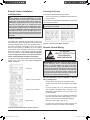
INSTALLATION AND
OPERATION MANUAL
Gas-Fired Pool
and Spa Heater
Brass ASME and Polymer Low NOx Heat
Exchanger Models
207A, 266L, 267A, 337A, 399L, and 407A
6000.592B_PoolSpa_LoNOx .indd 1 12/17/2019 11:21:17 AM

2
Revision 3 reects the following changes:
Model description amended on page 1. Note added on page 3. Text added to point 6 on page 6. Table L information and caption text
updated on page 15. 3rd Note added on page 15. Text revised in Note on page 16. Figure 22 revised on page 16. 1st paragraph
revised in "Pressure Relief Valve Installation" on page 17. Point 6 revised in "Heat Exchanger Removal" on page 30. Point 4 in
"Desooting Procedure" revised on page 31. Point 2 revised in "Winterizing the Pool and Spa Heater" on page 34. Illustration updated
on page 41. Parts list updated on page 43.
QUICK START GUIDE
CLEARANCES
Space required: See page 11.
Minimum and service clearances: See page 7 for
clearances table. Note that local codes prevail.
PIPING
Pressure relief valve: See page 17 for recommended
PRV orientation.
Flow rates: See page 15 for ow rate values.
GAS
Distance to regulator (pipe lengths) and gas inlet
sizes: See page 14.
Required pressure for Natural Gas:
Min = 5" WC, Max = 10.5" WC
Sediment trap is required for all installations:
See page 13.
WATER CHEMISTRY
Water chemistry requirements: See page 5.
POWER
Supply voltage: See page 20 for acceptable input
voltages.
VENTING
Materials: See pages 8, 10 and 12.
D-2 Power Vent Kit: See page 12.
Indoor Stack kit: See page 9.
CONTROLS INTERFACE
Wiring diagram: See page 21.
User interface: See page 22.
Remote operation: See page 26.
6000.592B_PoolSpa_LoNOx .indd 2 12/17/2019 11:21:17 AM

3
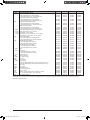
CONTENTS
1. WARNINGS ............................................................. 4
Pay Attention to These Terms ................................. 4
2. WATER CHEMISTRY ............................................. 5
Automatic Chlorinators and Chemical Feeders....... 5
3. BEFORE INSTALLATION ...................................... 6
Receiving equipment............................................... 6
Rating and certications .......................................... 6
Elevation ................................................................. 6
Ambient Temperature Rating .................................. 6
4. INSTALLATION ....................................................... 6
Installation Codes ................................................... 7
Clearances .............................................................. 7
Outdoor Heater Installation ..................................... 7
Combustion and Ventilation Air ............................... 9
Vent Piping ............................................................ 12
D-2 Power Vent Kit ................................................ 12
Gas Supply Connections....................................... 13
Flow Rates ............................................................ 14
ProTek Shield Assembly........................................ 15
Unitherm Governor Operation ............................... 16
Internal Automatic Bypass Valve ........................... 16
External Auxiliary Bypass Valve ............................ 17
Auxiliary Bypass Valve Adjustment ....................... 17
Pressure Relief Valve Installation .......................... 17
Plumbing Diagram................................................. 18
Heat Exchanger Reversal ..................................... 19
5. ELECTRICAL WIRING ......................................... 19
Electrical Power Draw ........................................... 20
Transformer Wiring ............................................... 20
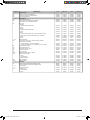
6. WIRING DIAGRAM ............................................... 21
7. CONTROLS ........................................................... 22
Control Panel Removal ......................................... 22
Control Adjustments ............................................. 22
Operation .............................................................. 23
Status and Diagnostics ......................................... 25
Remote Control Installation and Operation ........... 26
Remote Control Wiring .......................................... 26
8. OPERATING INSTRUCTIONS ............................ 32
Before Start-Up ..................................................... 32
Start-Up Procedures ............................................. 32
9. MAINTENANCE AND CARE ............................... 34
Cold Weather Operation .......................................34
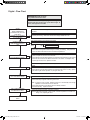
10. TROUBLESHOOTING ......................................... 35
Digital - Flow Chart................................................ 36
Control Logic - Flow Chart .................................... 37
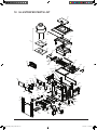
11. REPLACEMENT PARTS ..................................... 38
12. ILLUSTRATED PARTS LIST .............................. 39
NOTE: ProTek Shield Adapter and assembly for ASME models shown in Figures, but not available until March 2020.
6000.592B_PoolSpa_LoNOx .indd 3 12/17/2019 11:21:17 AM

4
AA
DANGER: Failure to install the drafthood on indoor
installation and properly vent the heater to the outdoors
as outlined in the venting section of this manual can
result in unsafe operation of the heater. To avoid the risk
of re, explosion, or asphyxiation from carbon monoxide,
never operate this heater unless it is properly vented
and has an adequate air supply for proper operation. Be
sure to inspect the vent system for proper installation at
initial start-up, and at least annually thereafter. Refer to
the venting section of this manual for more information
regarding vent system inspections.
AA
WARNING: Gasoline, as well as other ammable
materials and liquids (adhesives, solvents, etc.), and
the vapors they produce, are extremely dangerous. Do
not handle, use, or store gasoline or other ammable or
combustible materials in the vicinity of a heater.
AA
WARNING: Improper installation, adjustment,
alteration, service, or maintenance can cause property
damage, personal injury or loss of life. Installation
and service must be performed by a qualied installer,
service agency, or the gas supplier.
AA
WARNING: Do not install within 3 feet (0.9 m) of
a heat pump or an outdoor condensing unit. Strong
air intake from this type of equipment can disturb the
combustion process and cause damage or personal
injury.
AA
WARNING: UL-recognized fuel gas detectors are
recommended in all enclosed propane and natural
gas applications wherein there is a potential for an
explosive mixture of fuel gas to accumulate and their
installation should be in accordance with the detector
manufacturer’s recommendations and/or local laws,
rules, regulations, or customs.
AA
WARNING: The heater shall not be located in an
area where water sprinklers, or other devices, may cause
water to spray through the cabinet louvers and into the
heater. This could cause internal rusting or damage
electrical components, and void the warranty.
1. WARNINGS
Pay Attention to These Terms
AA
DANGER
Indicates the presence of immediate hazards which will cause severe personal injury, death or
substantial property damage if ignored.
AA
WARNING
Indicates the presence of hazards or unsafe practices which could cause severe personal injury,
death or substantial property damage if ignored.
AA
CAUTION
Indicates the presence of hazards or unsafe practices which could cause minor personal injury
or product or property damage if ignored.
CAUTION
CAUTION used without the warning alert symbol indicates a potentially hazardous condition
which could cause minor personal injury or product or property damage if ignored.
NOTE
Indicates special instructions on installation, operation, or maintenance which are important but
not related to personal injury hazards.
AA
WARNING: Both natural gas and propane have
an odorant added to aid in detecting a gas leak. Some
people may not physically be able to smell or recognize
this odorant. If you are unsure or unfamiliar with the
smell of natural gas or propane, ask your local gas
supplier. Other conditions, such as “odorant fade,”
which causes the odorant to diminish in intensity, can
also hide, camouage, or otherwise make detecting a
gas leak by smell more dicult.
AA
WARNING: To minimize the possibility of improper
operation, serious personal injury, re, or damage to the
heater:
• Always keep the area around the heater free of
combustible materials, gasoline, and other ammable
liquids and vapors.
• Heater should never be covered or have any blockage
to the ow of fresh air to the heater.
AA
WARNING: This unit contains refractory ceramic
ber (RCF) insulation in the combustion chamber. RCF,
as manufactured, does not contain respirable crystalline
silica. However, following sustained exposure to very
high temperatures [greater than 2192°F (1200°C)], the
RCF can transform into crystalline silica (cristabolite).
The International Agency for Research on Cancer
(IARC) has classied the inhalation of crystalline silica
(cristabolite) as carcinogenic to humans.
When removing the burners or heat exchangers, take
precautions to avoid creating airborne dust and avoid
inhaling airborne bers. When cleaning spills, use wet
sweeping or High Eciency Particulate Air (HEPA)
ltered vacuum to minimize airborne dust. Use feasible
engineering controls such as local exhaust ventilation
or dust collecting systems to minimize airborne dust.
Wear appropriate personal protective equipment
including gloves, safety glasses with side shields, and
appropriate NIOSH certied respiratory protection,
to avoid inhalation of airborne dust and airborne ber
particles.
6000.592B_PoolSpa_LoNOx .indd 4 12/17/2019 11:21:17 AM

5
AA
CAUTION: Elevated water temperature can be
hazardous. The U.S. Consumer Product Safety
Commission has these guidelines:
1. Spa water temperatures should never exceed
104°F (40°C). A temperature of 100°F (38°C) is
considered safe for a healthy adult. Special caution
is suggested for young children.
2. Drinking of alcoholic beverages before or during spa
or hot tub use can cause drowsiness which could
lead to unconsciousness and subsequently result in
drowning.
3. Pregnant Women Beware! Soaking in water over
102°F (39°C) can cause fetal damage during the rst
three months of pregnancy resulting in the birth of a
brain-damaged or deformed child. Pregnant women
should stick to the 100°F (38°C) maximum rule.
4. Before entering the spa or hot tub, users should
check the water temperature with an accurate
thermometer; spa or hot tub thermostats may err
in regulating water temperatures by as much as 4°F
(2.2°C).
5. Persons with a medical history of heart disease,
circulatory problems, diabetes, or blood pressure
problems should obtain a physician’s advice before
using pools or hot tubs.
6. Persons taking medications which induce
drowsiness, such as tranquilizers, antihistamines,
or anticoagulants, should not use spas or hot tubs
.
Recommended Level(s) Fiberglass Pools Fiberglass Spas Other Pool and Spa Types
Water Temperature 68-88°F (20-31°C) 89-104°F (31-40°C) 68-104°F (20-40°C)
pH 7.3-7.4 7.3-7.4 7.6-7.8
Total Alkalinity (ppm) 120-150 120-150 80-120
Calcium Hardness (ppm) 200-300 150-200 200-400
Salt (ppm) 4500 Maximum 4500 Maximum 4500 Maximum
Free Chlorine (ppm)* 2-3 2-3 2-3
Total Dissolved Solids (ppm) 3000 Maximum** 3000 Maximum** 3000 Maximum**
*Free Chlorine MUST NOT EXCEED 5 ppm!
**In saltwater chlorinated pools, the total TDS can be as high as 6000 ppm.
Table A. Pool Water Chemistry
2. WATER CHEMISTRY
NOTE: Corrosive water voids all warranties.
Chemical imbalance can cause severe damage to your
heater and associated equipment. Maintain your water
chemistry according to Table A. If the mineral content
and dissolved solids in the water become too high, scale
forms inside the heat exchanger tubes, reducing heater
eciency and damaging the heater. If the pH drops below
7.2, this will cause corrosion of the heat exchanger and
severely damage the heater. Heat exchanger damage
resulting from chemical imbalance is not covered by
the warranty.
For your health and the protection of your pool equipment,
it is essential that your water be chemically balanced. The
following levels must be used as a guide for balanced
water.
AA
CAUTION: Free chlorine must not exceed 5 ppm
which can damage the heater and is not covered under
warranty.
• Occasional chemical shock dosing of the pool or spa
water should not damage the heater providing the
water is balanced.
• Automatic chemical dosing devices and salt
chlorinators are usually more efficient in heated
water, unless controlled, they can lead to excessive
chlorine level which can damage your heater.
• Check valve should be installed between the heater
outlet and a chlorinator or other chemical dosing
device.
• Further advice should be obtained from your pool
or spa builder, accredited pool shop, or chemical
supplier for the correct levels for your water.
Automatic Chlorinators
and Chemical Feeders
All chemicals must be introduced and completely diluted
into the pool or spa water before being circulated through
the heater. Do not place sanitizing chemicals in the
skimmer. High chemical concentrations will result when
the pump is not running (e.g. overnight).
Chlorinators must feed downstream of the heater and
have an anti-siphoning device to prevent chemical backup
into the heater when the pump is shut o.
See "Plumbing Diagram" on page 18.
NOTE: High chemical concentrates from feeders and
chlorinators that are out of adjustment will cause rapid
corrosion to the heat exchanger. Such damage is not
covered under the warranty.
6000.592B_PoolSpa_LoNOx .indd 5 12/17/2019 11:21:17 AM

6
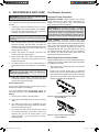
3. BEFORE INSTALLATION
Receiving equipment
The manufacturer recommends that this manual be
reviewed thoroughly before installing the pool/spa heater. If
there are any questions that this manual does not answer,
please contact the factory or your local representative.
On receipt of your equipment it is suggested that you
visually check for external damage to the carton. If the
carton is damaged, a note should be made on the Bill
of Lading when signing for the equipment. Remove the
heater from the carton. If it is damaged, report the damage
to the carrier immediately. Save the carton.
These items are shipped inside a box in the carton with
the heater:
Standard Unit (POLYMER HEADERS)
1. “Pagoda” top
2. 2" CPVC union half with "O" rings (2)
3. Plastic pipe finish flange for gas line
4. Bonding lug with mounting screw
ASME Unit (BRASS HEADERS)
1. “Pagoda” top
2. 2" CPVC union half with "O" rings (2)
3. Plastic pipe finish flange for gas line
4. Bonding lug with mounting screw
5. Pressure Relief Valve
6. Protek Shield™ Adapter with Protek Shield Assy,
O-ring and wing nut (March 2020 onward)
F10639-1
THE MODEL AND SERIAL NO.
CAN ALSO BE FOUND INSIDE
THE BEZEL ABOVE THE DISPLAY
MODEL AND SERIAL NO.
LOCATED ON RATING PLATE
Figure 1. Rating Plate Location
Be sure that you receive the number of packages indicated
on the Bill of Lading.
Rating and certications
These heaters are design-certied and tested under the
latest requirements of the ANSI Z21.56 / CSA 4.7 Standard
for Gas-Fired Pool Heaters. All heaters can be used either
indoor or outdoors when appropriate venting is installed.
The appropriate top designated for each type of use is
required. If necessary, the top can be changed at a later
date to change from outdoor to indoor or vice versa.
Elevation
Rated inputs are suitable for up to 5,000 feet (1524 m)
elevation. For elevations above 5,000 feet (1524 m),
consult the factory.
Ambient Temperature Rating
Heater Components
Electronic Ignition Heater* -32°F to 175°F (-35°C to 79°C)
*Requires 120 or 240VAC, 1 Ph, 60 Hz Power Supply
4. INSTALLATION
AA
WARNING: This unit contains refractory ceramic
ber (RCF) insulation in the combustion chamber. RCF,
as manufactured, does not contain respirable crystalline
silica. However, following sustained exposure to very
high temperatures (>2192°F), the RCF can transform
into crystalline silica (cristabolite). The International
Agency for Research on Cancer (IARC) has classied
the inhalation of crystalline silica (cristabolite) as
carcinogenic to humans.
When removing the burners or heat exchangers, take
precautions to avoid creating airborne dust and avoid
inhaling airborne bers. When cleaning spills, use wet
sweeping or High Eciency Particulate Air (HEPA)
ltered vacuum to minimize airborne dust. Use feasible
engineering controls such as local exhaust ventilation
or dust collecting systems to minimize airborne dust.
Wear appropriate personal protective equipment
including gloves, safety glasses with side shields, and
appropriate NIOSH certied respiratory protection,
to avoid inhalation of airborne dust and airborne ber
particles.
IMPORTANT NOTICE: These instructions are intended
only for the use by qualied personnel, specically
trained and experienced in the installation of this type
of heating equipment and related system components.
Installation and service personnel may be required by
some states to be licensed. If your state is such, be sure
your contractor bears the appropriate license. Persons
not qualied shall not attempt to x the equipment nor
attempt repairs according to these instructions.
6000.592B_PoolSpa_LoNOx .indd 6 12/17/2019 11:21:18 AM

7
AA
WARNING: Improper installation, adjustment,
alteration, service or maintenance may damage the
equipment, create a hazard resulting in asphyxiation,
explosion or re, and will void the warranty.
NOTE: The heater should not be located in an area
where possible water leakage will result in damage to
the area adjacent to the heater or to the structure. When
such locations cannot be avoided, it is recommended
that a suitable drain pan, with adequate drainage, be
installed under the heater. The pan must not restrict
combustion air ow.
Installation Codes
Installation must be in accordance with local codes, or,
in the absence of local codes, with the latest edition of
the National Fuel Gas Code, ANSI Z223.1/NFPA54 and
National Electrical Code, ANSI/NFPA 70, and for Canada,
the latest edition of CAN/CSA-B149 Installation Codes,
and Canadian Electrical Code, CSA C22.1 Part 1 and
Part 2.
Clearances
All Heaters
For indoor and outdoor clearances from combustible
surfaces, see the chart below.
Location Indoor Installation
Top * 30" (762 mm) Drafthood
Front Alcove (Open)
Vent 6" (152 mm)
Floor ** 0"
Back 6" (152 mm)
Right Side 12" (305 mm) Water Side
Left Side 6" (152 mm) Opposite Water Side
Location Outdoor Installation
Top * Unobstructed (Outdoor Stack)
Top *** 36" (914 mm) (Stackless Top)
Floor 0"
Back 6" (152 mm)
Right Side 12" (305 mm) Water Side
Left Side 6" (152 mm) Opposite Water Side
* Clearance from top of vent terminal
** Do not install on carpeting
*** Clearance from top of heater
Table B. Minimum Clearances from Combustible Surfaces
When installed according to the listed minimum clearances
from combustible construction, the pool heater can still be
serviced without removing permanent construction around
the heater.
However for ease of servicing, we recommend a clearance
of at least 24" (610 mm) in the front, and at least 18"
(457 mm) on the water connection side. This will enable
the heater to be serviced in its installed location, that is,
without movement or removal of the heater.
Clearances less than these may require removal of the
heater to service either the heat exchanger or the burner
tray. In either case, the heater must be installed in a
manner that will enable the heater to be serviced without
removing any structure around the heater.
Flooring
This heater can be installed on combustible ooring.
The combustible clearances listed can be reduced by
protecting the exposed combustible surfaces as shown in
Table C.
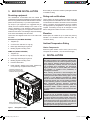
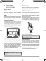
Outdoor Heater Installation
These heaters are design-certied for outdoor installation,
when equipped with the approved tops designated for
outdoor use.
AA
WARNING: The heater shall not be located in an
area where water sprinklers, or other devices, may cause
water to spray through the cabinet louvers and into the
heater. This could cause internal rusting or damage
electrical components, and void the warranty.
AA
WARNING: Do not install within 3' (0.9 m) of a heat
pump or an outdoor condensing unit. Strong air intake
from this type of equipment can disturb the combustion
process and cause damage or personal injury.
PAGODA TOP
INSTALLATION
F10647-2
Figure 2. Heater with Outdoor Stackless Top
6000.592B_PoolSpa_LoNOx .indd 7 12/17/2019 11:21:18 AM

8
Description Location
Distance
in. (mm)
a. 3-1/2" (89 mm) thick
masonry walls without
ventilated air space
Back 9 (229)
Right 9 (229)
Left 9 (229)
Vent 5 (127)
Indoor Top 39 (991)
Outdoor Top Unobstructed
b. 1/2" (13 mm)insulation
board over 1" (25 mm)
glass ber or mineral
wool batts
Back 6 (152)
Right 6 (152)
Left 6 (152)
Vent 3 (76)
Indoor Top 30 (762)
Outdoor Top Unobstructed
c. 0.024 sheet metal over
1" (25 mm) glass ber
or mineral wool batts
reinforced with wire on
rear face with ventilated
air space
Back 4 (102)
Right 4 (102)
Left 4 (102)
Vent 3 (76)
Indoor Top 24 (610)
Outdoor Top Unobstructed
d. 3-1/2" (89 mm) thick
masonry wall with
ventilated air space
Back 6 (152)
Right 6 (152)
Left 6 (152)
Vent 6 (152)
Indoor Top 39 (991)
Outdoor Top Unobstructed
e. 0.024 sheet metal with
ventilated air space
Back 4 (102)
Right 4 (102)
Left 4 (102)
Vent 2 (51)
Indoor Top 24 (610)
Outdoor Top Unobstructed
f. 1/2" (13 mm) thick
insulation board with
ventilated air space
Back 4 (102)
Right 4 (102)
Left 4 (102)
Vent 3 (76)
Indoor Top 24 (610)
Outdoor Top Unobstructed
g. 0.024 sheet metal with
ventilated air space over
0.024 sheet metal with
ventilated air space.
Back 4 (102)
Right 4 (102)
Left 4 (102)
Vent 3 (76)
Indoor Top 24 (610)
Outdoor Top Unobstructed
h. 1" (25 mm) glass ber
or mineral wool batts
sandwiched between two
sheets 0.024 sheet metal
with ventilated air space
Back 4 (102)
Right 4 (102)
Left 4 (102)
Vent 3 (76)
Indoor Top 24 (610)
Outdoor Top Unobstructed
Derived from National Fuel Gas Code, Table 10.2.3
Table C. Reduction of Clearances to Protected Surfaces
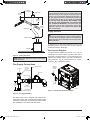
Heaters must not be installed under an overhang of less
than three 3' (0.9 m) from the top of the heater. Three sides
must be open in the area under the overhang. Roof water
drainage must be diverted away from the heaters installed
under overhangs with the use of gutters.
For U.S. installations, the point from where the ue
products exit the heater must be a minimum of 4' (1.2 m)
below, 4' (1.2 m) horizontally from, or 1' (0.3 m) above any
door, window or gravity inlet into any building. The top
surface of the heater shall be at least 3' (0.9 m) above
any forced air inlet, or intake ducts located within 10' (3 m)
horizontally.
For Canadian installations, pool heaters shall not be
installed with the top of the vent assembly within 10' (3 m)
below, or to either side, of any opening into the building.
Refer to the latest revisions of CAN/CSA-B149.
A minimum of 6' (1.8 m) is required from the heater to an
inside corner wall for proper outdoor venting.
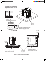
For installations in Florida and Texas, that must comply
with the Florida or Texas Building Code, follow the directions
shown in Figure 7 for the installation of hurricane tie-down
brackets for all models.
Forced Air Inlet
4' (1.2 m)
Minimum
3' (0.9 m)
Minimum
10' (3 m)
Minimum
1' (0.3 m)
Minimum
4' (1.2 m)
Minimum
4' (1.2 m)
Minimum
Figure 3. Clearances
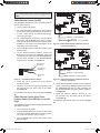
Pagoda Top Installation
1. Insert tabs into keyhole (4 places). See Figure 4,
detail A.
2. Snap tabs into keyholes so as not to pull out. See
Figure 4, detail B.
OUTDOOR TOP
(SHIPPED LOOSE WITH HEATER)
DETAIL A DETAIL B
Figure 4. Outdoor Top Installation
Indoor Heater Installation
The heater is also design-certied for indoor installation
when equipped with the approved drafthood.
6000.592B_PoolSpa_LoNOx .indd 8 12/17/2019 11:21:19 AM

9
For Canada, indoor installation is restricted to an enclosure
that is not occupied and does not directly communicate
with an occupied area. Refer to the latest edition of CAN/
CSA-B149 for specic requirements. Locate heater as
close as is practical to a chimney or gas vent. Heater
must always be vented to the outside. See section "Vent
Piping" on page 12 for details. Minimum allowable
space is shown on the nameplate.
AA
WARNING: Indoor heaters require a drafthood that
must be connected to a vent pipe and properly vented to
the outside. Failure to follow this procedure can cause
re or fatal carbon monoxide poisoning.
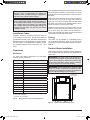
Outdoor and Indoor Stacks
The outdoor and indoor stacks are optional equipment
and do not come standard with the heater. Refer to
installation instructions inside box for instructions on
how to install outdoor/indoor stack.
Model
Outdoor Stack Indoor Stack
Part No Part No.
207A 009834 009838
266L/267A 009835 009839
337A 009836 009840
399L/407A 009837 009841
Table D. Outdoor and Indoor Stack Kit Number
NOTE: The outdoor drafthood kit does not require any
additional vent pipe for proper operation. This drafthood
functions as the vent termination.
Combustion and Ventilation Air
Indoor Units Only
The heater must have both combustion and ventilation
air. The minimum requirements are listed in the latest
edition of the National Fuel Gas Code (U.S. ANSI Z223.1
or Canada CAN/CSA-B149) and any local codes that
may have jurisdiction. The most common approach is
the "2-opening" method, with combustion air opening no
more than 12" from the oor and the ventilation opening
no more than 12" from the ceiling. For opening sizes using
this method, see below.
All Air from Inside the Building:
Each opening shall have a minimum net free area as
noted:
Model Sq. in. (m
2
)
207A 200 (0.13)
266L/267A 266 (0.17)
337A 333 (0.21)
399L/407A 399 (0.26)
Table E. Opening Minimum Net Free Requirements -
Indoor Air
All Air from Outdoors:
When air is supplied directly from outside the building, each
opening shall have a minimum net free area as noted:
Model
Unrestricted
Opening
sq. in. (m²)
Typical Screened
or Louvered
Opening
sq. in. (m²)
Typical Screened
and Louvered
Opening
sq. in. (m²)
207A 50 (0.03) 75 (0.05) 100 (0.1)
266L/267A 67 (0.04) 101 (0.06) 134 (0.09)
337A 84 (0.05) 126 (0.08) 168 (0.11)
399L/407A 100 (0.06) 150 (0.1) 200 (0.13)
Table F. Opening Minimum Net Free Requirements -
Outdoor Air
AA
CAUTION: Combustion air must not be contaminated
by corrosive chemical fumes which can damage the
heater. Such damage will not be covered by the warranty
INDOOR STACK KIT
(1) Drafthood, unpainted
(1) Adapter plate
(3) Mounting brackets (clips)
(3) Screws
(1) Instructions
Clips
OUTDOOR STACK KIT
(1) Outdoor stack, painted
(1) Adapter plate
(3) Mounting brackets (clips)
(1) Top panel cover
(2) 1-foot sections of metal tape
(3) Screws
(1) Instructions
Clips
Figure 5. Outdoor Stack Kit Components
Figure 6. Indoor Stack Kit Components
6000.592B_PoolSpa_LoNOx .indd 9 12/17/2019 11:21:19 AM

10
TOH
B
28"
(709 mm)
31-13/16"
(792 mm)
3" (76 mm)
Min. Conc.
Pad by others
3" (76 mm)
Min. Conc.
Pad by others
(1)–1/4" x 1-3/4" S.S. Tapcon
Bolt & Washer (Field-Supplied)
Ea. Pallet Anchor Bracket
Use hole closest to unit (4 total)
(1)–1/4" x 1-3/4" S.S.
Tapcon Bolt & Washer (Field-Supplied)
Ea. Pallet Anchor Bracket
Use hole closest to unit (4 total)
2" x 6" x 1/8" Pallet
Anchor Bracket (4 Total) (Kit# 011636)
1/4" x 1-3/4" S.S.
Tapcon Bolt and Washer (Field-Supplied)
NOTE: Use hole closest to unit with
washer overlapping edge of unit.
Min. Edge
Distance
6"
(152 mm)
Min. Edge
Distance
6"
(152 mm)
F10649
Model
B
in. (mm)
207A 20 (508)
266L/267A 23 (584)
337A 26 (660)
399L/407A 29 (737)
Florida and Texas Building Code:
Wind Speed = 150 mph 3 sec gust
Exposure = C
Figure 7. Hurricane Tie-Down Bracket Installation
6000.592B_PoolSpa_LoNOx .indd 10 12/17/2019 11:21:20 AM

11
Heater
Model
BTUH
Input
(000)
(kw)
(A)
Cabinet
Width
in. (mm)
(B)
Flue
Dia.
in.
(mm)
(C)
Indoor
Drafthood
in. (mm)
(D)
in. (mm)
(J)*
in. (mm)
Gas
Conn.
in.
Water
Conn.
in.
Shipping Weights - lbs (kg)
Standard
Heater
w/Stackless
Top
ASME
Heater
w/Stackless
Top
Indoor
Draft-
hood
207A
199.5
(58.4)
20
(508)
6
(152)
55-5/8
(1413)
10.0
(254)
11-3/4
(298)
3/4 2
174
(79)
193
(88)
14
(6.4)
266L
266.0
(77.9)
23
(584)
7
(178)
56
(1422)
11.5
(292)
11
(279)
3/4 2
197
(89)
N/A
16
(7.3)
267A
216
(98)
337A
332.5
(97.4)
26
(660)
8
(203)
57
(1448)
13.0
(330)
10-5/8
(270)
3/4 2
219
(99)
238
(108)
19
(8.6)
399L
399
(116.9)
29
(737)
9
(229)
58-1/2
(1486)
14.5
(368)
12-1/2
(318)
3/4 2
237
(108)
N/A
21
(9.5)
407A
256
(116)
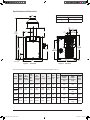
Table G. Heater Specications and Dimensions
Specications and Dimensions
Figure 8. Front View
20-1/2"
(521 mm)
31-13/16"
(792 mm)
DRAFTHOOD
B
A
J*D
C
7-3/4"
(197 mm)
F10647
INDOOR
GAS
CONNECTION
26-1/2"
(673 mm)
ELECTRICAL
CONNECTION
28"
(711 mm)
34"
(867 mm)
STACKLESS
OUTDOOR
TOP
4-3/8"
(111 mm)
8-7/8"
(225 mm)
(6-5/8" ASME)
(168 mm ASME)
10"
(254 mm)
F10647-1
C
L
FLUE
Amp Draw
120 VAC, 1 Ph, 60 Hz 240 VAC, 1 Ph, 60 Hz
6 3
Figure 9. Side View
*Note: For outdoor stack, use J dimension in the table below for appropriate size plus 6" (152 mm).
6000.592B_PoolSpa_LoNOx .indd 11 12/17/2019 11:21:20 AM

12
Vent Piping
AA
WARNING: Indoor heaters require a drafthood that
must be connected to a vent pipe and properly vented to
the outside. Failure to follow this procedure can cause
re or fatal carbon monoxide poisoning.
When properly installed outdoors, only the outdoor
stackless top, provided, is required. If installed indoors,
a drafthood is required, connected to a CATEGORY
I (a heater that operates with a non-positive vent static
pressure and a vent gas temperature that avoids excessive
condensate production in the vent) vent per the National
Fuel Gas Code and local requirements.
Vent piping the same size as the drafthood outlet is
recommended, however, when the total vent height is at
least 10 ft (3 m) (drafthood relief opening to vent terminal),
the vent pipe size may be reduced by no more than one
size as specied in Chapter 13 of the National Fuel Gas
Code, ANSI Z223.1 (Canada - CAN/CSA-B149).
As much as possible, avoid long horizontal runs of vent
pipe and too many elbows. If installation requires horizontal
runs, the vent pipe must have a minimum of 1/4 in. per ft
rise (20.8 mm per meter rise) and should be supported at
not more than 5 ft (1.5 m) intervals.
Plumber's tape, criss-crossed, will serve to space both
horizontal and vertical piping. Gas vents supported only
by the ashing and extending above the roof more than 5
ft (1.5 m) should be securely guyed or braced to withstand
snow and wind loads. We recommend use of insulated
vent pipe spacers through the roof and walls.
For protection against rain or blockage by snow, the vent
pipe must terminate with a vent cap which complies with
the local codes or, in the absence of such codes, to the
latest edition of the National Fuel Gas Code, ANSI Z223.1
(Canada - CAN/CSA-B149).
The discharge opening must be a minimum of 2' (0.6
m) vertically from the roof surface and at least 2' (0.6 m)
higher than any part of the building within 8' (2.4 m). Vent
stack shall be at least 5' (1.5 m) in vertical height above
the drafthood outlet. The vent cap location shall have a
minimum clearance of 4' (1.2 m) horizontally from, and in
no case below, unless a 4' (1.2 m) horizontal distance is
maintained, from electric meters, gas meters, regulators
and relief equipment.
The weight of the vent stack or chimney must not rest on the
heater drafthood. Support must be provided in compliance
with applicable codes. The heater top and drafthood must
be readily removable for maintenance and inspection.
Vent pipe should be adequately supported to maintain
proper clearances from combustible construction.
Flue materials must be certied to CATEGORY I or
better. Type “B” double-wall or equivalent vent pipe is
recommended. A draft of -0.01" to -0.08" WC must be
maintained. However single-wall metal vent pipe may be
used as specied in the latest edition of the National Flue
Gas Code, ANSI Z223.1 (Canada - CAN/CSA-B149).
D-2 Power Vent Kit
Another option for an installation that requires horizontal
runs is using the D-2 power vent kit option.
Model 120 VAC P/N 240 VAC P/N
207A 010744 009832
266L/267A 010744 009832
337A 010745 009833
399L/407A 010745 009833
Table H. Power Vent Kit Part Numbers
NOTE: The D-2 Power Vent operates with a positive vent
static pressure and with a vent gas temperature that
prevents excessive condensate production in the vent,
and as such, is a CATEGORY III appliance. For more
information consult the D-2 Power Vent manual, Catalog
no 6000.57.1. CATEGORY I vent material such as B-vent
must not be used under CATEGORY III conditions.
Figure 10. D-2 Power Vent Option
The power vent system is a fan-assisted vent system
designed for application used on models 207A-407A.
The power vent system, when installed as directed, is
capable of operating in applications such as through-the-
wall venting with reduced horizontal and vertical vent pipe
sizes in new and current installations. The unit is factory-
wired for 240 VAC, with capability of eld-rewiring for 120
VAC.
For more information consult the D-2 Power Vent manual,
(Catalog No. 6000.57.1).
6000.592B_PoolSpa_LoNOx .indd 12 12/17/2019 11:21:21 AM

13
AA
CAUTION: The heater and its manual shut-o valve
must be disconnected from the gas supply during any
pressure testing of that system at test pressures in
excess of 1/2 psi (3.45 kPa). Dissipate test pressure in
the gas supply line before reconnecting the heater and
its manual shut o valve to gas supply line. FAILURE
TO FOLLOW THIS PROCEDURE MAY DAMAGE THE
GAS VALVE. OVER PRESSURIZED GAS VALVES ARE
NOT COVERED BY WARRANTY. The heater and its gas
connections shall be leak tested before placing the
appliance in operation. Use soapy water for leak test. DO
NOT use open ame.
Supply Pressure
AA
CAUTION: Do not use teon tape on gas line pipe
thread. Only sealant tape or a pipe compound rated for
use with natural and propane gases is recommended.
Apply sparingly only on male pipe ends, leaving the two
end threads bare.
A minimum of 5 in. WC and a maximum of 10.5 in. WC
upstream pressure under load and no-load conditions
must be provided for natural gas.
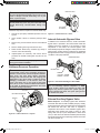
Gas Pressure Regulator
The gas pressure regulator is preset at 3.1 in. WC for
natural gas. The pressure at the gas valve, taken with a
manometer, should be about 3.1 in. WC natural gas. If an
adjustment is needed, remove seal and turn adjustment
screw clockwise
to increase pressure or counter-
clockwise to decrease pressure.
MANUAL
SHUT-OFF
VALVE
UNION
F10639-4
Figure 13. Manual Shut-O Valve Installation
VENT CAP
2' MIN
(0.6 m)
VENT PIPE
DRAFT HOOD
5' MIN
(1.5 m)
HEATER
2' MIN
(0.6 m)
8' (2.4 m)
OR LESS
Figure 11. Venting Clearances
NOTE: With venting application of two or more heaters,
contact the factory.
Gas Supply Connections
GAS INLET
HEATER JACKET
MANUAL
SHUT-OFF
VALVE
(Field supplied)
GAS VALVE
FINISH FLANGE
UNION
(Field supplied)
SEDIMENT TRAP
(Field supplied)
3" MIN
(76 mm)
Typical
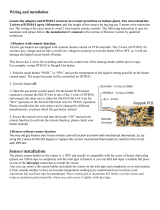
Figure 12. Gas Supply Plumbing
Gas piping must have a sediment trap ahead of the
heater gas controls, and a manual shut-o valve located
outside the heater jacket. All gas piping should be tested
after installation in accordance with local codes.
6000.592B_PoolSpa_LoNOx .indd 13 12/17/2019 11:21:22 AM

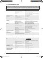
14
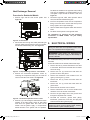
Gas Pressure Adjustment Locations
Gas Pressure Adjustment
Figure 14. Honeywell VR8340
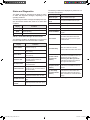
Pipe Sizing for Gas Connection
The capacities shown below are based on using SCH
40 black iron pipe. For capacities using other materials,
consult local codes.
Maximum Equivalent Pipe Length (ft) (m)
Natural Gas 1000 BTU/FT
3
0.60 Specic Gravity @ 0.5 in.
WC Pressure Drop
Model 3/4" 1" 1-1/4" 1-1/2"
207A 25 (7.6) 90 (27.4) 360 (109.7) n/a
266L/267A 15 (4.6) 50 (15.2) 210 (64.0) 445 (135.6)
337A 10 (3.0) 30 (9.1) 140 (42.7) 290 (88.4)
399L/407A * 20 (6.1) 95 (29.0) 215 (65.5)
* A 3/4" gas line can be used for up to 5' (1.5 m) maximum length from the gas
valve in addition to the sediment trap.
Table I. Gas Pipe Sizing
Flow Rates
Model Pipe Size Min. GPM (lpm) Max. GPM (lpm)
207A 1-1/4"–1-1/2"–2" 20 (75) 125 (473)
266L/267A 1-1/4"–1-1/2"–2" 25 (95) 125 (473)
337A 1-1/4"–1-1/2"–2" 35 (132) 125 (473)
399L/407A 1-1/4"–1-1/2"–2" 40 (151) 125 (473)
* When ow rates exceed maximum GPM an external auxiliary bypass valve is
required. See external bypass valve section for details.
Table J. Min/Max Flow Rates
F10638-1
Figure 15. Polymer Headers Water Flow
F10637-1
Figure 16. Brass Headers (ASME) Water Flow
Flow GPM
(lpm)
Pressure Drop
Ft. of Head (m of Head)
207A 266L/267A 337A 399L/407A
20 (75) 4.0 (1.2)
25 (95) 4.0 (1.2) 4.6 (1.4)
30 (113) 4.0 (1.2) 5.2 (1.6)
35(132) 4.0 (1.2) 5.8 (1.8) 5.2 (1.6)
40 (151) 4.6 (1.4) 5.8 (1.8) 5.2 (1.6) 5.2 (1.6)
50 (189) 4.6 (1.4) 6.3 (1.9) 6.9 (2.1) 6.9 (2.1)
60 (227) 4.6 (1.4) 6.9 (2.1) 6.9 (2.1) 6.9 (2.1)
70 (265) 4.6 (1.4) 8.1 (2.5) 9.2 (2.8) 9.2 (2.8)
80 (303) 4.6 (1.4) 9.2 (2.8) 9.8 (3.0) 9.8 (3.0)
90 (340) 6.9 (2.1) 10.4 (3.2) 10.4 (3.2) 10.4 (3.2)
100 (378) 8.1 (2.5) 11.0 (3.4) 12.1 (3.7) 12.1 (3.7)
110 (416) 10.4 (3.2) 11.5 (3.5) 13.3 (4.0) 13.3 (4.0)
120 (454) 11.0 (3.4) 12.7 (3.9) 17.9 (5.4) 17.9 (5.4)
125 (473) 11.5 (3.5) 13.8 (4.2) 20.2 (6.2) 20.2 (6.2)
Table K. Polymer Heat Exchanger Pressure Drop -
Residential Models (UG Fully Open)
6000.592B_PoolSpa_LoNOx .indd 14 12/17/2019 11:21:23 AM

15
Flow GPM
(lpm)
Pressure Drop
Ft. of Head (m of Head)
207A 267A 337A 407A
20 (75) 8.2
30 (113) 9.5 9.5
40 (151) 9.7 9.7 11 13.4
50 (189) 10 9.8 12.2 13.4
60 (227) 11 10.4 13.7 13.5
70 (265) 11.5 10.9 14.3 14
80 (303) 12.6 12 15.5 15
90 (340) 14 13 16.2 16.2
100 (378) 15 14.2 17.5 16.7
Table L. Brass Heat Exchanger Pressure Drop - ASME
Models (UG Closed)
NOTE: Table capacity is based on Schedule 40 black
iron pipe. For capacity using other material, consult
local codes.
Brass Headers (ASME Models)
Heater must be located so that any water leaks will not
damage the structure of adjacent area. Before attaching
the ProTek Shield Adapter to the inlet connection and the
2-inch unions, make sure the O-rings are properly seated
in the grooves. Use Aqualube or equivalent non-petroleum-
based lubricant on the O-ring. Hand tighten the unions.
Glue PVC piping directly to the unions.
F10664
HEADER
O-RING
HEADER FLANGE
(CPVC)
HEADER FLANGE NUT
(CPVC)
PLUMBING
PROTEK SHIELD
ASSEMBLY
Figure 18. Inlet/Outlet Header – Brass
NOTE: Some jurisdictions require the addition of a ow
switch on ASME installations. Kit # 015889F for ange
connection or 015890F for NPT connection can be
ordered that will allow a standard ASME unit to comply
with the code requirements.
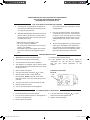
ProTek Shield Assembly
This heater is equipped with a ProTek Shield Assembly
(located under the inlet connection on polymer headers
and in the ProTek Shield Adapter assembly shipped loose
in the accessory carton for eld installation on brass ASME
headers).
NOTE: ProTek Shield not available on ASME models
until March 2020.
This component provides protection to the heat exchanger
against galvanic corrosion, when properly bonded to the
heat exchanger. It should be replaced when the weight of
the ProTek Shield is reduced to about 40% of the original
weight (1.46 #).
F10715
Figure 19. ProTek Shield Assy
Polymer Headers (Residential Models)
Before attaching the 2-inch unions to the inlet/outlet
header, make sure the O-rings are properly seated in
the grooves. Use Aqualube or equivalent non-petroleum-
based lubricant on the O-ring. Hand tighten the unions.
Glue PVC piping directly to the unions.
F10641
O-RING
HEADER FLANGE
(CPVC)
HEADER FLANGE NUT
(CPVC)
PROTEK
SHIELD
ASSY
PLUMBING
Figure 17. Inlet/Outlet Header – Polymer
High temperature CPVC header anges and header
ange nuts are provided. If there is any possibility of back-
siphoning when the pump stops, it is suggested that a
check valve (or valves) also be installed in the system.
6000.592B_PoolSpa_LoNOx .indd 15 12/17/2019 11:21:24 AM

16
AA
CAUTION: STOP the pool pump before attempting
to remove ProTek Shield Assembly. Failure to do so may
result in damage to ProTek Shield Assy, loss of pool
water, or personal injury.
CAUTION: Do not use tools to remove (twist) the
ProTek Shield Assy or the wing nut on the stud of the
ProTek Shield Assy. Non-warrantable damage may
occur.
Follow the steps below to replace the ProTek Shield Assy:
1. Shut off the pool pump and bleed pressure from the
system.
2. Close isolation valves to minimize pool/spa water
loss.
3. Remove wing nut from bottom stud on ProTek Shield
Assy.
4. Remove bonding wire ring terminal from stud.
5. Rotate ProTek Shield Assy clockwise (by hand) to
unscrew it from the assembly.
6. Inspect/replace as necessary and reverse above
procedure to reinstall. Hand tighten only! Do not use
tools.
NOTE: Make sure the O-ring is properly seated in the
O-ring groove before installation.
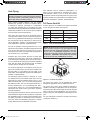
Unitherm Governor Operation
AA
CAUTION: The patented Unitherm Governor is
a thermostatic mixing valve specically designed to
maintain constant heater internal temperature between
105°F (41°C) and 115°F (46°C) despite continually
changing ow rates from the lter and changing pool
temperatures. This narrow range is needed to prevent
damaging condensation on the burners which will
occur if the heater runs for any length of time below
100°F (38°C). It is also needed to inhibit scale formation
in the tubes by maintaining temperatures well below
accelerated scaling temperatures.
F10725
GASKET
UG PLUG
UNITHERM GOVERNOR
Figure 20. Unitherm Governor – Polymer
F10642-2
UG/BYPASS ASSY
UNITHERM
GOVERNOR
Figure 21. Unitherm Governor – Brass
Internal Automatic Bypass Valve
In addition to the Unitherm Governor, a built-in automatic
bypass valve is provided in the In/Out header. While the
Unitherm Governor responds to the changes in water
temperature in the heater, the internal bypass valve
automatically responds to changes in water pressure in the
piping system. Proper amount of water ow is maintained
through the heater under varying pressures dictated by the
conditions of the pump and lter.
F10642-4
UG/BYPASS ASSY
BYPASS DISC
SPRING
"YELLOW" - 206/266
"GREEN" - 336/406
Figure 22. Internal Automatic Bypass Valve ASME
NOTE: The Unitherm Governor and Bypass Valve Assy
are not individually replaced components on ASME
units. If either needs to be replaced, the entire UG/
Bypass assy must be replaced. The "yellow" spring is
used on models 207A, 267A. The "green" spring is used
on models 337A, 407A.
External Auxiliary Bypass Valve
Where Required - An auxiliary bypass valve should be
used when ow rates exceed 125 GPM (473 lpm). Usually
a high-performance pump size larger than two horsepower
will exceed this ow rate. This valve is required to
complement the function of the automatic bypass valve,
particularly when starting the heater in winter or early
spring when the spa or pool temperature is below 50°F
(10°C). It also serves to eliminate needless pressure drop
through the heater and accompanying reduction in the ow
rate to the spa jets, etc.
6000.592B_PoolSpa_LoNOx .indd 16 12/17/2019 11:21:25 AM

17
FROM HEATER
TO HEATER
TO POOL/SPA
FROM POOL/SPA
FULL PORT
BALL VALVE
OR GLOBE
VALVE
BYPASS VALVE
Do not use gate valve.
Figure 23. Auxiliary Bypass Valve
Auxiliary Bypass Valve Adjustment
To set bypass - With clean lter, adjustment is made by
feeling the inlet and outlet pipes at the heater. Outlet pipes
should be slightly warmer than inlet and comfortable to the
touch. If pipe is hot, close bypass; if cold, open bypass.
Pressure Relief Valve Installation
To conform to local building codes, it may be necessary
to install a pressure relief valve. A 3/4" pressure relief
valve, having a capacity equal to or greater than the BTU
output of the model to be installed, is recommended for
this heater.
A 3/4" NPT connection is provided in the Polymer header
for installation of a pressure relief valve. The valve shall be
installed in a vertical position. Do not over-tighten. Install
pressure relief valve hand tight plus 1/2 turn.
F10662
IN/OUT HEADER
PRV DISCHARGE
CONNECTION
PRESSURE RELIEF VALVE
Figure 24. Field-Supplied Pressure Relief Valve Polymer
Header (Residential Units)
A 3/4" NPT connection is provided in the header for
installation of a 75 PSI (517 kPa) pressure relief valve.
The PRV is shipped loose in the accessory carton with the
pagoda top. The valve pressure relief shall be installed in
a vertical position.
F10663
PRESSURE RELIEF VALVE
Figure 25. Pressure Relief Valve Brass Header
(ASME Models)
NOTE: To avoid water damage or scalding due to valve
operation, drain pipe must be connected to valve outlet
and run to a safe place of discharge. Drain pipe must
be the same size as the valve discharge connection
throughout its entire length and must pitch downward
from the valve. No shut-o valve shall be installed
between the relief valve and the drain line. Valve lever
should be tripped at least once a year to ensure that
waterways are clear.
The heater requires water ow and positive pressure to
re and operate properly. It must therefore be installed
downstream of the discharge side of the lter pump. See.
Figure 29 and Figure 30.
A typical installation is plumbed as follows:
1. The inlet side of the filter is plumbed directly to the
discharge side of the filter pump;
2. The outlet side of the filter is then plumbed to the inlet
of the heater; and
3. The outlet of the heater is plumbed to the return line
to the pool or spa. The pump, filter and heater are
thus plumbed in series (Salt generators and chemical
feeders must be down stream of the pool heater).
Plumbing from the heater back to the pool or spa must not
have any valves or restriction that could prevent ow when
the pump is operating.
AA
CAUTION: An additional source of heated water,
e.g. a solar system, must be connected to the main line
ahead of the heater inlet pipe in order for it to act as
the primary heat source. If the primary system provides
adequate heat to maintain setpoint, the heater will not
re. Be advised that the control panel will then display
sensed water temperatures downstream of the primary
heating system, rather than the temperature of the water
exiting the pool.
Heater must be located so that any water leaks will not
damage the structure of adjacent area. PVC pipe may be
glued directly into the headers unions.
6000.592B_PoolSpa_LoNOx .indd 17 12/17/2019 11:21:26 AM

18
Plumbing Diagram
Water Connection
THIS DIAGRAM IS A RECOMMENDATION AND IS NOT INTENDED
TO REPACE AN ENGINEERED PIPING SYSTEM BY A PROFESSIONAL ENGINEER
Figure 29. Single Pool Heater Installation
THIS DIAGRAM IS A RECOMMENDATION AND IS NOT INTENDED
TO REPACE AN ENGINEERED PIPING SYSTEM BY A PROFESSIONAL ENGINEER
Figure 30. Multiple Pool Heater Installation
ISOLATION
VALVE
PRESSURE
RELIEF VALVE
PUMP
UNION
CHECK VALVE
BALL VALVE
6000.592B_PoolSpa_LoNOx .indd 18 12/17/2019 11:21:26 AM

19
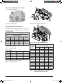
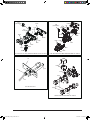
Heat Exchanger Reversal
Procedure for Residential Models
1. Remove right and left side access panels. See
Figure 26.
F10652
Figure 26. Access Panels
2. Disconnect wires at high limit, AGS (automatic gas
shut-off), water pressure switch on the in/out header,
and ProTek Shield bonding wire. See Figure 27.
F10653
Figure 27. Component Wiring Locations – In/Out Header
3. Remove the thermostat temperature sensor by
loosening the compression fitting nut. Re-route the
sensor to left side of the heater. See Figure 28.
F10654
Figure 28. Thermostat Temperature Sensor Location
4. Remove (12) nuts holding the inlet/outlet and return
headers to the tube sheets. Clean off tube sheet
area where the gasket seats. Also clean off the
header and the gasket. Apply a non-petroleum-
based lubricant to the gasket such as Aqualube.
Re-attach the headers to the opposite sides, making
sure they are installed in an upright position. Do not
over-tighten. Torque should not exceed 7 ft/lb. See
Figure 27.
5. Reconnect high limit, AGS, water pressure switch
wires, and ProTek Shield bonding wire.
6. Insert the temperature sensor into the compression
fitting, so that the sensor is flush with the top of the
fitting. Tighten 1/2 turn past hand tight.
7. Allow for water flow through the heater and check for
leaks.
8. Re-attach access panels to the opposite sides.
For instructions on reversing the heat exchanger
connections on ASME models, call your factory
representative.
5. ELECTRICAL WIRING
NOTE: If it is necessary to replace any of the original
wiring, use 105°C wire or its equivalent, and/or 150°C
wire or its equivalent, like the original wiring.
AA
WARNING: Digital heaters are factory-wired for
240 VAC, 1Ph, 60Hz power supply. DO NOT attempt to
operate at 208 VAC.
The standard eld-wiring connection is on the right side of
the heater.
To wire the heater from the left side, follow these steps:
1. Remove the two (2) screws that hold the front door
to the heater. Remove and set aside door for better
access to wiring.
2. Remove the four (4) screws that hold down the
junction box to the sway brace.
3. Remove the transformer cover located on the far
right by removing one (1) screw.
4. Remove the two (2) screws that hold down the
transformer.
5. Remove the one (1) screw that holds down the
ground wires.
6. Disconnect P6 connector from PC board.
7. Remove transformer from its current location and
relocate it on the far left side of the heater.
8. Re-route all high-voltage wires and ground wires
through the left jacket side of heater.
9. Re-install P6 connector, ground wires (SPG),
transformer, junction box, front door, and plug right
side with the left side’s grommet plug.
NOTE: 7/8" diameter holes not utilized on jacket and
control box can be used for reman switch, auxiliary
control interface or power vent (D-2) wiring.
6000.592B_PoolSpa_LoNOx .indd 19 12/17/2019 11:21:27 AM

20
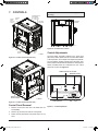
Electrical Power Draw
AA
CAUTION: Heater must be electrically grounded and
bonded. Bonding lug is provided loose with the heater.
Install bonding lug on lower right or left side of jacket
as necessary for bonding the heater. Mounting hole is
provided on the jacket.
NOTE: Failure to ground the heater electrically could
aect the heater’s electronics.
NOTE: See "Time Clock/Fireman’s Switch" on page
28 for further instructions if using a time clock/
reman’s switch.
The Electronic Intermittent Ignition Device automatically
lights the pilot and main burners upon a call for heat. The
heater is supplied with a dual-voltage transformer for 120
VAC or 240 VAC input power hookup.
When operating on 120VAC power, units draw 6 amps.
When operating on 240VAC units draw 3 amps.
OPTION LOCATION
LEFT SIDE FIELD WIRING
CONTROL BOX
(FACTORY MOUNTED
LOCATION)
SWAY BRACE
BONDING LUG
(STANDARD
LOCATION)
BONDING LUG
(OPTIONAL
LOCATION)
F10651
Figure 31. Heater Wiring Locations
Transformer Wiring
120 VAC Wiring
For 120 VAC input power to the unit, connect the black
wire to the L1 or hot leg of the power supply. Connect the
white wire to the “Ret” or neutral leg of the power supply.
There should be no connection to the red wires for
120 VAC operation. Attach a wire nut to each red wire
independently.
SUPPLY
SIDE
RETURN
or
NEUTRAL
HEATER
7 WIRES
L1
HOT
RED
RED
BLACK BLACK
BLACK
GREEN GREEN
WHITE WHITE
WHITE
GROUND
Figure 32. 120 VAC Wire Connection Models
240 VAC Wiring
For 240 VAC input power to the unit, connect the black
wire to the L1 or hot leg of the power supply. Connect the
red wire to the “L2” or second hot leg of the power supply.
There should be no connection to the white wires for
240 VAC operation. Attach a wire nut to each white wire
independently.
AA
WARNING: DO NOT attempt to operate the heater
at 208 VAC.
240V LOW NOx HEATER
HEATER
7 WIRES
GROUND
L1
L2
BLACK
BLACK
RED
RED
RED
HOT
HOT
BLACK
GREEN GREEN
WHITE
WHITE
SUPPLY
SIDE
Figure 33. 240 VAC Wire Connection
The heater must be electrically grounded and bonded in
accordance with local codes, or, in the absence of local
codes, with the latest edition of the National Electrical
Code, ANSI/NFPA 70. (Canada - Canadian Electrical
Code, CSA C22.1, Part 1 and Part 2.)
CAUTION: If the transformer’s primary side is wired for
120 VAC and 240 VAC is applied, damage to the trans-
former and PC board may result. Such damages are not
covered under manufacturer’s limited warranty.
NOTE: Input power to the heater (120 or 240 VAC) can be
supplied from the load (pump) side of time clock or directly
from the GFCI power source. It is preferred that full-time
power be supplied to the heater from the GFCI power
source, and that the heater be controlled by the reman’s
switch connection or using a two or three-wire remote. If
using a switched GFCI power source, the heater could display
false service indicators on the display panel if the pump is
turned o.
6000.592B_PoolSpa_LoNOx .indd 20 12/17/2019 11:21:28 AM
Page is loading ...
Page is loading ...
Page is loading ...
Page is loading ...
Page is loading ...
Page is loading ...
Page is loading ...
Page is loading ...
Page is loading ...
Page is loading ...
Page is loading ...
Page is loading ...
Page is loading ...
Page is loading ...
Page is loading ...
Page is loading ...
Page is loading ...
Page is loading ...
Page is loading ...
Page is loading ...
Page is loading ...
Page is loading ...
Page is loading ...
Page is loading ...
Page is loading ...
Page is loading ...
-
 1
1
-
 2
2
-
 3
3
-
 4
4
-
 5
5
-
 6
6
-
 7
7
-
 8
8
-
 9
9
-
 10
10
-
 11
11
-
 12
12
-
 13
13
-
 14
14
-
 15
15
-
 16
16
-
 17
17
-
 18
18
-
 19
19
-
 20
20
-
 21
21
-
 22
22
-
 23
23
-
 24
24
-
 25
25
-
 26
26
-
 27
27
-
 28
28
-
 29
29
-
 30
30
-
 31
31
-
 32
32
-
 33
33
-
 34
34
-
 35
35
-
 36
36
-
 37
37
-
 38
38
-
 39
39
-
 40
40
-
 41
41
-
 42
42
-
 43
43
-
 44
44
-
 45
45
-
 46
46


Raypak 207A-407A User manual
- Category
- Above ground pool accessories
- Type
- User manual
- This manual is also suitable for
Ask a question and I''ll find the answer in the document
Finding information in a document is now easier with AI
Related papers
-
Rheem P-M267A-EN-C Owner's manual
-
Raypak 268 & 408 User manual
-
-
-
-
Raypak 009200 User manual
-
-
-
-
Raypak 408 Installation & Operating Instructions Manual
Other documents
-
 International Controls & Measure ACH060 Installation guide
-
Pentair Pool Products 250K BTU/HR Installation and User Manual
-
Pentair 250K BTU/HR User manual
-
Bradford White D-65T-625-3NA Quick Service Guide
-
 Energy Tech Laboratories 8357 User manual
-
STA-RITE Max-E-Therm SR200NA User manual
-
 ThermoMart DTH101-P Gas Pool Heater Owner's manual
-
-
-
Dirt Killer Portable Hot Water Pressure Washers User manual


