Page is loading ...

PELLET STOVE
Evolution
PLEASE READ THIS ENTIRE MANUAL BEFORE INSTALLATION AND USE
OF THIS PELLET BURNING ROOM HEATER. FAILURE TO FOLLOW THESE
INSTRUCTIONS COULD RESULT IN PROPERTY DAMAGE, BODILY INJURY
OR EVEN DEATH
Contact your building or fire officials about restrictions and installation
inspection requirements in your area.
SHERWOOD INDUSTRIES IS AN ENVIRONMENTALLY RESPONSIBLE COMPANY. THIS MANUAL IS PRINTED ON RECYCLED
PAPER.
PLEASE KEEP THESE INSTRUCTIONS FOR FUTURE REFERENCE
TECHNICAL MANUAL
50-1574

2
Safety Warnings & Recommendations...............................................................................................3
Installation.....................................................................................................................................6
Rating Label Location................................................................................................................6
Deciding Where to Locate your Pellet Appliance..........................................................................6
Removing Pellet Stove From Pallet.............................................................................................6
Dimensions..............................................................................................................................7
Clearances to Combustibles.......................................................................................................8
Alcove Clearances.....................................................................................................................8
Hearth Pad Pedestal Installation.................................................................................................9
Vent Termination Requirements................................................................................................10
Outside Fresh-Air Connection...................................................................................................11
Exhaust And Fresh Air Intake Locations....................................................................................11
Mobile Home Installation.........................................................................................................12
Corner Through Wall Installation..............................................................................................12
Horizontal Exhaust Through Wall Installation.............................................................................13
Through Wall With Vertical Rise and Horizontal Termination Installation- Recommended..............14
Through Concrete Wall With Vertical Rise Installations...............................................................14
Inside Vertical Installations......................................................................................................15
Outside Vertical Installations....................................................................................................15
Hearth Mount Installation........................................................................................................16
Exterior Mounted Exhaust Blower.............................................................................................17
Typical Through Wall With Exterior Blower Kit Installation - Horizontal Termination......................18
Typical Through Wall With Exterior Blower Kit Installation - Vertical Termination..........................19
Thermostat Installation............................................................................................................20
Optional Slider/Damper Installation..........................................................................................20
Slider/Damper Set-Up..............................................................................................................21
Troubleshooting............................................................................................................................22
Wiring Diagram.............................................................................................................................25
Parts List......................................................................................................................................26
Parts Diagram - Components..........................................................................................................28
Parts Diagram - Steel.....................................................................................................................29
Installation Data Sheet..................................................................................................................30
Table of Contents

3
Safety Warnings & Recommendations
* This manual is designed for the technician in conjunction with the owner’s manual. *
Please read this entire Owner’s Manual before installing or operating your ENVIRO Pellet
Stove. Failure to follow these instructions may result in property damage, bodily injury or
even death. Any unauthorized modification of the appliance or use of replacement parts
not recommended by the manufacturer is prohibited. All national and local regulations and
European Standards shall be complied with when installing this appliance.
Caution: Do not connect to any air distribution duct or system.
Warning: Parts of the appliance, especially the external surfaces, will be hot to touch when
in operation so use due care and the fire gloves provided. Never place wood, paper, furniture,
drapes or other combustible materials within 80cm (31”) of the front of the unit, 20cm (7”) from
each side, and 10cm (4”) from the back of the unit. Do not let children or pets touch it when it is hot.
To prevent the possibility of a fire, ensure that the appliance is properly installed by adhering to the
installation instructions. An ENVIRO dealer will be happy to assist you in obtaining information with
regards to your local building codes and installation restrictions.
FIRE EXTINGUISHER AND SMOKE DETECTION: All homes with a pellet burning stove should have
at least one fire extinguisher in a central location known to all in the household. Smoke detectors should
be installed and maintained in the room containing the stove when installing and operating a pellet
burning appliance. If it sounds the alarm, correct the cause but do not deactivate. You may choose to
relocate the smoke detection devise within the room; DO NOT REMOVE THE SMOKE DETECTOR FROM
THE ROOM.
CHIMNEY OR RUN AWAY FIRE: Call local fire department. Close the draft fully. Extinguish the fire
in the burn pot liner with a cup of water and close the door. Examine the flue pipes, chimney, attic, and
roof of the house, to see if any part has become hot enough to catch fire. If necessary, spray with fire
extinguisher or water from the garden hose. IMPORTANT: Do not operate the stove again until you are
certain the chimney and its lining have not been damaged.
FUEL: This pellet stove is designed and approved to only burn wood pellet fuel with up to 3% ash content.
Dirty fuel will adversely affect the operation and performance of the unit and may void the warranty.
Check with your dealer for fuel recommendations. THE USE OF CORDWOOD IS PROHIBITED BY
LAW. When filling fuel hopper, open lid on top of unit, check hopper for foreign objects, empty the
bag into the hopper, DO NOT OVER FILL, and ensure hopper lid closes completely. DO NOT use this
appliance as an incinerator. DO NOT use unsuitable and non recommended fuels, including liquid fuels.
KEEP ASH PAN FREE OF RAW FUEL. DO NOT PLACE UNBURNED OR NEW PELLET FUEL IN ASH PAN.
A fire in the ash pan may occur.
SOOT: Operation of the stove with insufficient combustion air will result in the formation of soot which
will collect on the glass, the heat exchanger, the exhaust vent system, and may stain the outside of the
house. This is a dangerous situation and is inefficient. Frequently check your stove and adjust the slider/
damper as needed to ensure proper combustion. See: “SLIDER/DAMPER SETTING”.

4
Safety Warnings & Recommendations
CLEANING: There will be some build up of fly ash and small amounts of creosote in the exhaust. This
will vary due to the ash content of the fuel used and the operation of the stove. It is advisable to inspect
and clean the exhaust vent semi-annually or every two tons of pellets. The appliance, flue gas connector
and the chimney flue require regular cleaning. Check them for blockage prior to re-lighting after a
prolonged shut down period.
ASHES: Disposed ashes should be placed in a metal container with a tight fitting lid. The closed container
of ashes should be on a non-combustible surface, well away from all combustible materials pending final
disposal. If the ashes are disposed of by burial in soil or otherwise locally dispensed, they should be
retained in the closed container until all cinders have been thoroughly cooled.
IMPORTANT: The door and ash drawer cover must be kept closed except during ignition, refueling and
removal of residue material to prevent fume spillage.
GLASS: Do not abuse the glass by striking or slamming the door. Do not attempt to operate the stove
with broken glass. The stove uses ceramic glass. Replacement glass must be purchased from an ENVIRO
dealer. Do not attempt to open the door and clean the glass while the unit is in operation or if glass is
hot. To clean the glass, use a soft cotton cloth and mild window cleaner, gas or wood stove glass cleaner,
or take a damp paper towel and dip into the fly ash. This is a very mild abrasive and will not damage the
glass.
ELECTRICAL: The use of a surge protected power bar is recommended. The unit must be
grounded. The grounded electrical cord should be connected to a standard 220-240 volts (2.0-2.3 Amps),
50 hertz electrical outlet and also must be accessible. If this power cord should become damaged, a
replacement power cord must be purchased from the manufacturer or a qualified ENVIRO dealer. Be
careful that the electrical cord is not trapped under the appliance and that it is clear of any hot surfaces
or sharp edges. This unit’s maximum power requirement is 525 watts.
OPERATION: The door and ash drawer cover must be kept closed securely when the unit is in operation
to prevent fume spillage and for proper and safe operation of the pellet stove. Also ensure all gaskets on
the door are checked and replaced when necessary.
CAUTION: When operating during adverse weather, if the unit exhibits dramatic changes in combustion
stop using the unit immediately.
INSTALLATION: Contact your local building or fire official to obtain a permit and any information on
installation restrictions and inspection requirements for your area. All local regulations, including those
referring to national and European Standards need to be complied with when installing this appliance.
Be sure to maintain the structural integrity of your home when passing a vent through walls, ceilings, or
roofs. It is recommended that the unit be secured into its position in order to avoid any displacement. This
appliance must be installed on a floor with an adequate load bearing capacity. If an existing construction
doesn’t meet these prerequisite, suitable measures (e.g. load distributing plate) shall be taken to achieve
it.
DO NOT INSTALL A FLUE DAMPER IN THE EXHAUST VENTING SYSTEM OF THIS UNIT.
DO NOT CONNECT THIS UNIT TO A CHIMNEY FLUE SERVING ANOTHER APPLIANCE.

5
Safety Warnings & Recommendations
FRESH AIR: Outside Fresh Air connection is optional. Fresh Air must be connected to all units installed
in “Air Tight Homes” or where required by local codes.
Consider all large air moving devices when installing your unit and provide room air accordingly. NOTE:
Extractor fans when operating in the same room or space as the appliance, may cause problems. Limited
air for combustion may result in poor performance, smoking and other side effects of poor combustion.
The stove’s exhaust system works with negative combustion chamber pressure and a slightly positive
chimney pressure. It is very important to ensure that the exhaust system be sealed and airtight. The ash
pan and viewing door must be locked securely for proper and safe operation of the pellet stove.
Do not burn with insufficient combustion air. A periodic check is recommended to ensure proper
combustion air is admitted to the combustion chamber. Setting the proper combustion air is achieved by
adjusting the slider damper located on the left side of the stove.
Minor soot or creosote may accumulate when the stove is operated under incorrect conditions such as an
extremely rich burn (black tipped, lazy orange flames).
If you have any questions with regards to your stove or the above-mentioned information, please feel
free to contact your local dealer for further clarification and comments.
SINCE SHERWOOD INDUSTRIES LTD. HAS NO CONTROL OVER THE INSTALLATION OF
YOUR STOVE, SHERWOOD INDUSTRIES LTD. GRANTS NO WARRANTY IMPLIED OR STATED
FOR THE INSTALLATION OR MAINTENANCE OF YOUR STOVE. THEREFORE, SHERWOOD
INDUSTRIES LTD. ASSUMES NO RESPONSIBILITY FOR ANY CONSEQUENTIAL DAMAGE(S).
SAVE THIS INSTRUCTION MANUAL FOR FUTURE REFERENCE

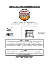
Remove the two (2)
wood screws (one
on either side of the
unit) to remove the
unit from the pallet.
Installation
RATING LABEL LOCATION:
The rating label is located on the inside of the ash pan cover.
DECIDING WHERE TO LOCATE YOUR PELLET APPLIANCE:
1. Check clearances to combustibles.
2. Do not obtain combustion air from an attic, garage or any unventilated space. Combustion air may
be obtained from a ventilated crawlspace.
3. Do not install the stove in a bedroom.
4. You can vent the stove through an exterior wall behind the unit or connect it to an existing masonry
or metal chimney (must be lined if the chimney is over 15 cm (6”) diameter, or over 180 cm² (28
inches²) cross sectional area). An interior vent can be used with approved pipe passing through the
ceiling and roof.
5. Locate the stove in a large and open room that is centrally located in the house. This will optimize
heat circulation.
6. The power cord is 2.43 m (8 feet) long and may require a grounded extension cord to reach the
nearest electrical outlet.
REMOVING PELLET STOVE FROM PALLET:
1. Remove the right and left hand cabinet
sides by loosening the three (3) T-20 Torx
screws on the back of the each panel.
2. Remove the one (1) screw located on the
front of the cabinet side, behind the top
louvers and one (1) screw behind the ash
door.
3. Remove the two (2) wood screws that are
holding the bottom of the stove to the
pallet.
4. Close the side panels.
Figure 1: Screws to take out to remove stove from pallet.
6

Installation
DIMENSIONS:
7
IMPORTANT: When not installing
the optional Hearth Pad on the
unit, the minimum requirements
for protection on combustibles
floors are a width of 620mm
(24”) & depth of 670mm
(26”) under the unit.
22
1
/4" (565 mm)
33
1
/16"
(840 mm)
21
1
/4"
(539 mm)
5
13
/16"
(147 mm)
26
3
/8" (670 mm)
27
7
/8"
(708 mm)
24
3
/8" (619 mm)
Figure 1: Dimensions of Evolution.
Table 1: Evolution Specifications.
Classification Testing Standard Description
Class I IP-20 EN14785:2006/EN13240:2001/A2:2004 Residential Wood Pellet Heater
Voltage Current Frequency
220 - 240 V 2.0 - 2.3 Amps 50 Hz
Maximum Power Requirement Fuel type Calorific value of Pellet used
525W (1793 BTU/hr) wood pellets - 6mm (”) dia. ≥ 5.10 kWh/kg (≥ 7900 BTU/lb)
Maximum Flue Gas Temperature Mean Flue Gas Temperature Mean Flue Gas Temperature (Reduced)
200°C (392°F) 192°C (378°F) 143°C (289°F)
Nominal Heat Output CO emissions from Combustion Energy Efficiency
7.6 KWh (25932 BTU) 0.032% 84%
Reduced Heat Output CO emissions from Combustion (Reduced Output) Energy Efficiency (Reduced Output)
3.2 KWh (10919 BTU) 0.045% 75%
CO
2
at Nominal Output Nominal Fuel Consumption Rate Unit with Full Hopper
8.35% 1.78 Kg/hr (3.95 lb/hr)* ~ 140kg (310lb)
CO
2
at Reduced Output Fuel Consumption Rate (Reduced Output) Hopper Capacity
3.45% 0.83 Kg/hr (1.85 lb/hr)* ~ 40kg (90lb)
*Note: Consumption will vary with the type of fuel used.
Unit Dimensions
Height: 840 mm (33
1
/16”)
Width: 565 mm (22 ”)
Depth: 539 mm (21 ”)
Hearth Pad:
Width: 619 mm (24 ”)
Depth: 708 mm (27 ”)

Installation
CLEARANCES TO COMBUSTIBLES:
This unit can be installed on a combustible floor when installed with the optional hearth pad part 50-1568
(for example linoleum, hardwood flooring). If this unit is to be installed onto a carpeted surface, a hearth
pad must be used for stability.
ALCOVE CLEARANCES:
This unit may be installed in an alcove.
Maintain these clearances to combustibles.
Minimum Alcove width 1220mm (48 inches)
Minimum Alcove height 1220mm (48 inches)
Maximum Alcove depth 1220mm (48 inches)
Install vent at clearances specified by
the vent manufacturer.
Side Wall
Back Wall
Adja
c
e
n
t
W
a
l
l
7
7
/8"
(20cm)
4"
(10cm)
4" (10cm)
48"
(122cm)
48"
(122cm)
48"
(122cm)
These dimensions are minimum clearances
but it is recommended that you ensure
sufficient room for servicing, routine cleaning
and maintenance.
Side wall to unit 200mm (7 inches)
Back wall to unit 100mm (4 inches)
Corner to unit 100mm (4 inches)
In Front of unit 800mm (31” inches)
Figure 3: Evolution Clearance to Combustibles.
Figure 4: Evolution Minimum Alcove Size.
8

9
Installation
HEARTH PAD PEDESTAL INSTALLATION:
This unit can be installed on a combustible floor (e.g. linoleum, hardwood flooring) when the Optional
Hearth Pad is installed. If this unit is to be installed onto a carpeted surface, a solid pad must be used
underneath the Optional Hearth Pad for stability.
Carefully place the the pellet appliance on its back, on the pallet (allow the exhaust tube to fit thru an
opening in the pallet). Align the holes in the hearth pad and the unit and install the four (4) screws
provided. Stand the unit back up. Adjust the leveling legs to below the Hearth Pad, to support the weight
of the unit.
When moving the unit - be careful not to damage the floor or the Hearth Pad.
Figure 5: Installing Hearth Pad Pedestal onto Evolution.

10
hot enough to cause burns if touched by children. Non-combustible shielding or guards may be required.
3. Termination must exhaust above the inlet elevation. It is recommended that at least five feet of vertical pipe be
installed outside when the appliance is vented directly through a wall, to create some natural draft to prevent the
possibility of smoke or odor during appliance shut down or power failure. This will keep exhaust from causing a
nuisance or hazard from exposing people or shrubs to high temperatures. In any case, the safest and preferred
venting method is to extend the vent through the roof vertically.
4. Distance from the bottom of the termination and grade is 30 cm (12 in) minimum. This is conditional upon the
plants and nature of grade surface. The exhaust gases are hot enough to ignite grass, plants and shrubs located
in the vicinity of termination. The grade surface must not be lawn.
5. If the unit is incorrectly vented or the air to fuel mixture is out of balance, a slight discoloration of the exterior
of the house might occur. Since these factors are beyond the control of Sherwood Industries Ltd, we grant no
guarantee against such incidents.
NOTE: Venting terminals shall not be recessed into walls or siding.
Installation
VENT TERMINATION REQUIREMENTS:
IT IS RECOMMENDED THAT YOUR PELLET STOVE BE INSTALLED BY AN AUTHORIZED DEALER/INSTALLER.
Figure 6: Use in conjunction with Table 2 for allowable exterior vent termination
locations.
Table 2: Use in conjunction with Figure 6 for allowable exterior vent termination locations.
Letter Minimum Clearance Description
A 61cm (24 in) Above grass, top of plants, wood, or any other combustible materials.
B
122 cm (48 in)
Beside/below any door or window that may be opened. (46 cm (18”) if outside
fresh air install.)
C
30 cm (12 in)
Above any door or window that may be opened. (23 cm (9”) if outside fresh air
install.)
D 61cm (24 in) To any adjacent building, fences and protruding parts of the structure.
E 61cm (24 in) Below any eave or roof overhang
F 30 cm (12 in) To outside corner.
G 30 cm (12 in) To inside corner, combustible wall (vertical and horizontal terminations).
H 91 cm (3 ft) within a height
of 4.5 m (15 ft) above the
meter/regulator assembly
To each side of center line extended above natural gas or propane meter/
regulator assembly or mechanical vent.
I 91 cm (3 ft) From any forced air intake of other appliance
J
30 cm (12 in)
Clearance to non-mechanical air supply inlet to building, or the combustion air
inlet to any appliance.
K 61cm (24 in) Clearance above roof line for vertical terminations.
L 2.13 m (7 ft) Clearance above paved sidewalk or paved driveway located on public property.
Air Supply Inlet
Gas Meter
Restriction Zone
(Termination not allowed)
Termination Cap
G
G
Opens
Opens
Opens
D
F
B
B
A
I
H
K
G
G
L
C
E
1. Do not terminate the
vent in any enclosed or
semi-enclosed areas such
as a carport, garage,
attic, crawlspace, narrow
walkway, closely fenced
area, under a sundeck
or porch, or any location
that can build up a
concentration of fumes
such as stairwells, covered
breezeway, etc.
2. Vent surfaces can become

Installation
OUTSIDE FRESH-AIR CONNECTION:
This Heater must have adequate air for proper combustion in the room that it is installed.
Figure 7: Outside Air Connection.
EXHAUST AND FRESH AIR INTAKE LOCATIONS:
The Exhaust Starter Tube can be installed 2 ways:
Angled towards the center - Use a Tee with vertical for a “centered” vertical installation.
Straight out the back - For horizontal thru the wall and up installation
EXHAUST Location:
Base of unit to center of flue 278mm (10
15
/
16”)
Center of unit to center of flue 35mm (1”)
FRESH AIR INTAKE.
Base of unit to center of intake 227mm (8
15
/
16”)
Center of unit to center of intake 105mm (4”)
8
15
/16"
(227 mm)
4
1
/8"
(105 mm)
1
3
/8"
(35 mm)
10
15
/16"
(278 mm)
Figure 8: Evolution Inlet and Outlet Location.
IMPORTANT: This unit must be connectect to an 80mm stainless steel vent pipe exhausting outside
the building.
A Fresh-air intake is strongly recommended for all
installations. Failure to install intake air may result in improper
combustion as well as the unit smoking during power failures.
The inlet to the intake must be below and a minimum of 305mm
(12”) away from the unit exhaust outlet.
Outside fresh air is mandatory when installing this unit
in airtight homes and mobile homes.
When connecting to an outside fresh air source, do not use
plastic or combustible pipe. A 50mm minimum (2”) ID (inside
diameter) steel, aluminum or copper pipe should be used. It is
recommended, when you are installing a fresh air system, to
keep the number of bends in the pipe to a minimum.
11

Figure 10: Corner Installation.
Installation
MOBILE HOME INSTALLATION:
4" (10 cm)
4"
(10 cm)
Fresh Air Intake
Wall thimble
manufactured
by pellet vent
manufacturer.
ENVIRO EF5
1
/4” Lag Bolts
Securely Fastened
Ground Wire Directly
to Metal Chassis
Optional
Hearth Pad
Flooring
Steel
Frame
● Secure the heater to the floor using the
two holes in the pedestal.
● Ensure the unit is electrically
grounded to the chassis of your home
(permanently).
● Do not install in a room people sleep in.
● Outside fresh air is mandatory. Secure
outside air connections directly to fresh
air intake pipe and secure with three
(3) screws evenly spaced.
CAUTION: THE STRUCTURAL
INTEGRITY OF THE
MANUFACTURED HOME FLOOR,
WALL AND CEILING/ROOF MUST
BE MAINTAINED.
CORNER THROUGH WALL INSTALLATION:
Figure 9: Mobile home installation.
12

13
Installation
HORIZONTAL EXHAUST THROUGH WALL INSTALLATION:
Vent installation: install vent at clearances specified by the vent manufacturer.
A chimney connector shall not pass through an attic or roof space, closet or similar concealed spaces,
or a floor, or ceiling. Where passage through a wall or partition of combustible construction is desired,
the installation must conform with all local regulations, including those referring to regional, national or
European Standards. Use 80mm stainless steel vent pipe to exhaust the unit to the outside.
1. Choose a location for your stove that meets the requirements stated in this manual and allows
installation with the least amount of interference to house framing, plumbing, wiring, etc.
2. Install a non-combustible hearth pad (where necessary).
3. Place the appliance 375 mm (15”) away from the wall. If the stove is to be set on a hearth pad, set
the unit on it.
4. Locate the center of the exhaust pipe on the stove. Extend that line to the wall. Once you have located
the center point on the wall, refer to pellet vent manufacturer installation instructions for correct hole
size and clearance to combustibles.
5. Install the wall thimble as per the instructions written on the thimble. Maintain an effective vapour
barrier in accordance with local building codes.
6. Install a length of 80mm (3”) vent pipe into the wall thimble. The pipe should install easily into the
thimble.
7. Install the fresh air intake (see OUTSIDE FRESH AIR CONNECTION).
8. Connect the exhaust vent pipe to the exhaust pipe on the stove. Seal the connection with high
temperature silicone.
9. Push the stove straight back, leaving a minimum of 100mm (4”) clearance from the back of the stove
to the wall. Seal the vent pipe to the thimble with high temperature silicone.
10. The pipe must extend at least 30 cm (12”) away from the building. If necessary, bring another
length of pipe to the outside of the home to connect to the first section. Do not forget to place high
temperature silicone around the pipe that passes through the thimble.
11. Install a vertical pipe, or if all requirements for direct venting are met, install vent termination. The
stainless steel cap termination manufactured by the vent manufacturer is recommended. However,
Figure 11: Straight through wall Installation.
when the vent terminates several feet above
ground level and there are no trees, plants,
etc. within several feet, a 45° elbow can be
used as termination. The elbow must be
turned down to prevent rain from entering.
NOTE:
• It is recommended that horizontal through wall
installations have 3 to 5 feet (91 to 152 cm)
of vertical pipe in the system to help naturally
draft the unit in the event of extreme weather
or a power outage.
• Some horizontal through wall installations may
require a “T” and 3 to 5 feet (91 to 152 cm) of
vertical pipe outside the building to help draft
the unit. This may be required if a proper burn
cannot be maintained, after the stove has
been tested and the airflow set. This is due
to the back pressure in the exhaust caused by
airflow around the structure.

Installation
THROUGH WALL WITH VERTICAL RISE AND HORIZONTAL TERMINATION INSTALLATION- RECOMMENDED:
Figure 12: Venting horizontally with rise.
A 45° down elbow with a rodent screen
may be used in place of the termination
cap (or stainless steel termination hood).
THROUGH CONCRETE WALL WITH VERTICAL RISE INSTALLATIONS:
Wall framing
Wall thimble
Termination cap
Vertical section
of vent pipe
Horizontal frame
for thimble
Clean out tee
90
o
elbow
EF 5
Concrete Wall
A 45° down elbow with a rodent screen
may be used in place of the termination cap
(or stainless steel termination hood).
Installation to use if there is a concrete or
retaining wall in line with exhaust vent on
pellet stove.
The termination must be 305mm (12”) from
the outside wall and 305mm (12”) above
the ground.
Figure 13: Venting with concrete wall behind unit .
14
• Follow vent manufacturer’s guidelines for installation of venting. High temperature sealant must be
used when connecting the vent pipe to the unit’s starter pipe. Improper seals at the vent joints may
cause combustion byproducts to leak into the room where installed - seal as required..

15
2 ft
(61 cm)
Rain Cap (ensure cap
is at least 3ft (91cm)
above the roof at the
lowest point)
Roof Flashing
Roof Rafter
Fire Stop with
Support Collar
Ceiling Joist
Vertical Vent Pipe
Clean Out Tee with
Pipe Adapter
EF 5
NOTE: All vent sections must
maintain 3 inches (7.6 cm)
clearances to combustibles.
Installation
INSIDE VERTICAL INSTALLATIONS:
1. Choose a stove location that is ideal. See the section “DECIDING WHERE TO LOCATE YOUR PELLET APPLIANCE.”
2. Place a non-combustible hearth pad where necessary.
Figure 14: Inside Vertical Installation.
3. Place the unit on the hearth pad (if
installed on a carpeted surface) and
space the unit in a manner so when
the pellet vent is installed vertically,
it will be 100mm (4”) away from a
combustible wall.
4. Locate the center of the fresh air
intake pipe on the unit. Match that
center with the same point on the
wall and cut a hole about 40mm
(1”) in diameter.
5. Install the fresh air intake pipe.
6. Install the tee with clean out.
7. Install the pellet vent upward
from there. When you reach the
ceiling, make sure that the vent
goes through the ceiling fire stop.
Maintain a 100mm (4”) distance
to combustibles and keep attic
insulation away from the vent pipe.
Maintain an effective vapor barrier.
8. Finally, extend the pellet vent to go
through the roof flashing.
9. Ensure that the rain cap is
approximately 900 mm (36”) above
the roof.
OUTSIDE VERTICAL INSTALLATIONS:
To accomplish a outside vertical pipe installation, follow steps 1 through 5 in the “INSIDE VERTICAL INSTALLATIONS
- FREESTANDING” section and then finish it by performing the following (refer to Figure 15).
1. Install a tee with clean out on the outside of the house.
2. Install vent pipe upward from the tee. Make sure that you install support brackets to keep the vent
straight and secure.
3. Install ceiling thimble and secure the flashing as you go through the roof.
4. Ensure that the rain cap is approximately 900 mm (36”) above the roof.

HEARTH MOUNT INSTALLATION:
EF 5
Existing Fireplace
Clean Out Tee
Fireplace Damper
Location
Rain Cap
Seal Plate
Vent Pipe (single
wall stainless flex
pipe or PL vent)
Existing Masonary
Flue
Flexible Vent Connector
(Use this 5 ft section of
pipe to vent past
fireplace damper or
smoke shelf)
Installation
Rain cap
Flashing
24"
(61 cm)
4"
(10cm)
Tee with
cleanout
Fresh air
intake
3" (7.5 cm)
Clearance
Support
bracket
Type "L"
vent
Figure 15: Outside Vertical Installation.
Figure 16: Hearth mount installation.
Refer to Figures 16.
1. Lock fireplace damper in the open position.
2. Install a positive flue connector at the
fireplace dampers.
3. Connect a tee or a 90° elbow to the exhaust
pipe.
4. Install flexible stainless steel liner or listed
pellet vent to the top of the chimney.
16

17
Installation
EXTERIOR MOUNTED EXHAUST BLOWER:
The Evolution can be equipped with an externally mounted exhaust blower. This optional kit includes all
components necessary to install the exhaust blower on any vertical wall surface.
1. Remove the left hand cabinet side by removing the two
(2) screws down the front. Loosen the three screws on the
back of the cabinet side and remove panel.
2. Loosen the six (6) screws that hold the back grill in place.
Lift the back grill off the screws.
3. Disconnect the Exhaust blower wires from the wire
harness. Remove the exhaust blower motor from the
housing; six (6) screws. Cover hole in housing with cover
plate provided (see Figure 18).
4. Remove the cover from the exhaust blower housing box.
5. Install the exhaust blower housing box into the pipe placed
through the wall thimble, seal with high temperature
silicone. Fasten the box to the wall with (4) four screws,
seal edges of box to wall with clear silicone.
6. Drill a hole through the wall thimble plate for the electrical
wires. Pass the armored cable through the wall thimble.
Use the strain relief provided. Do not pass cable
through vent hole.
7. Install the Exhaust Blower motor into the external exhaust
blower housing box. Make the electrical connections to the
wire harness and exhaust blower.
8. Replace the cover on the Exhaust Box and the back grill of
the stove and ensure the screws are tightened down.
9. Install vertical pipe as instructed in appropriate section.
Choose a location for your stove that meets the requirements
stated in your manual and allows installation with the least
amount of interference with house framing, plumbing,
wiring, etc.
Included in the Exterior Mounted Exhaust Blower Kit are:
1 - Exhaust blower housing box.
1 - Blower cover plate.
1 - Hardware bag
Figure 17: Exterior Blower Kit.
Figure 18: Exterior Blower Kit.
Figure 19: Exterior Blower Kit cut-through.

Installation
TYPICAL THROUGH WALL WITH EXTERIOR BLOWER KIT INSTALLATION - HORIZONTAL TERMINATION:
Electrical Cable
EF 5
90° Elbow
45°Elbow with Rodent
screen or stainless
steel termination hood
2ft Riser
Pipe Adaptor
Exterior Blower
and Housing
Wall Strap
To supply power
to the exhaust
Install an amour coated electrical cable from the exhaust blower housing, through the wall thimble plate
and attach to the pre drilled hole in the left hand rear hopper pillar. Hook up to wires from the exhaust
blower wiring harness.
All electrical connections must be in accordance to local code requirements
NOTE:
Ensure that all interior vent connections are sealed by placing a small bead of high temperature silicone
around each chimney connection.
Also ensure that all vertical vent sections are properly supported and that all clearances to combustibles
are maintained in accordance with the vent manufacturer’s specifications.
Figure 20: Through Wall Installation with Exterior Blower Kit.
Figure 21: Through Wall Installation with Exterior Blower Kit; Side View.
18

19
EF5
Roof Sheathing
Rain Cap
Roof Flashing
Roof Rafters
Ceiling Joists
Vent Pipe
Exterior Wall
Sheathing
Outside Vent
Termination
Installation
TYPICAL THROUGH WALL WITH EXTERIOR BLOWER KIT INSTALLATION - VERTICAL TERMINATION:
Follow the previous pages for through wall installations. Ensure that vent pipe is properly secured to wall
using wall straps. Maintain clearances to combustibles on vent pipe as well as unit.
Figure 22: Through Wall Installation with Exterior Blower Kit; Vertical Termination.

Installation
THERMOSTAT INSTALLATION:
1. Install the wall thermostat (12 or 24 Volt rated) in a location that is not to close too the unit but will
effectively heat the desired area.
2. Connect the Thermostat or Timer using an 2 x 18 gauge wire from the unit to the thermostat.
OPTIONAL SLIDER/DAMPER INSTALLATION:
If the unit has been placed in the HI / LOW mode, the unit
will be taken to a low or idle setting when the thermostat
is not calling for heat. When the thermostat calls for
heat, the unit will go to the setting that is displayed on
the control board Heat Indicator. If the heat in the room
becomes to great, the high limit switch may turn the
stove off and the switch will have to be manually reset.
To reset the high limit switch, remove the right cabinet
side. The switch is found behind the control panel. Avoid
setting off the high limit switch.
Slider damper
rod and knob
7
/16" Nut
7
/16" Clinching Nut
Slider damper plate
1. To install the OPTIONAL slider damper rod, remove the left cabinet
side and locate the slider damper plate. Install the
7
/16” (11mm)
nut onto the slider damper rod, thread all the way to the end of
the threads on rod.
2. Slide rod through the hole in the slider damper plate and install
the
7
/16” (11mm) clinching nut onto the rod and tighten completely
onto the slider damper plate.
3. Re-install the cabinet side. Install the black knob on the end of the
rod. Check slider damper for smooth operation.
Slider/
Damper
Knob
NOTE: NOT APPLICABLE FOR GERMANY AND
NEW ZEALAND
If you wish to adjust the slider damper externally (NOT
REQUIRED), please follow the instructions below.
Figure 24: Slider/Damper Assembly.
Figure 25: Slider/Damper Knob.
20
Remove jumper
wire and install
thermostat wires here.
Figure 23: Thermostat wire placement.
/