
29 June 2015 Page 4
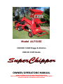
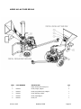
Model A17515E
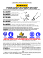
SAFETY WEAR
DO NOT wear loose clothing or jewellery that can be caught
by moving parts of your SuperChipper and pull you into it.
Keep all clothing away from moving parts. Wear adequate
headgear to keep hair away from moving parts. Always wear
safety glasses and work gloves at all times while operating
your SuperChipper. A chip could fly out and hit you in the eye.
Be sure your glasses fit properly and your gloves do not have
loose cuffs or draw strings.
Always wear ear protection at all times while operating your
SuperChipper. The noise of this machine could result in
hearing loss.
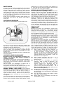
OPERATING PROCEDURE
Only operate your SuperChipper from the operator zone.
Know how to turn the unit off. DO NOT clear discharge area
while unit is running. Disconnect spark plug lead before
attempting to clear any discharge area.
DO NOT clear discharge area with hands, feet, or any other
part of your body. After SuperChipper is stopped and spark
plug lead is disconnected, then use a long handle tool to clear
discharge area.
DO NOT move your SuperChipper or leave it unattended with
the engine running.
OPERATE IN SAFE ENVIRONMENT
DO NOT operate your SuperChipper on slippery, wet,
muddy, or icy surfaces. Safe footing is essential in
preventing accidents.
Only operate on level ground. If level ground is impossible to
find, be sure the inclination from horizontal of the engine
when running is not more than 15 degrees to assure proper
engine lubrication.
DO NOT operate your SuperChipper on inclines over 10
degrees as it could become unstable and tip over.
Keep operator zone clean and clear of debris so that you don’t
stumble or trip over it, or become entangled with debris.
HANDLE PETROL WITH CARE as it is an extremely
flammable fuel. Check the fuel before starting the engine. Do
not fill the fuel tank indoors, while the engine is running, or
while the engine is still hot. Turn the unit off and let the
engine cool before refueling. Wipe the fuel cap and top of
fuel tank area before removing fuel cap to prevent dirt
entering tank.
Fuel your SuperChipper in a clean area to avoid getting dirt in
petrol tank. Do not smoke while refueling. Fuel tank cap
must be secure at all times except during refueling. Avoid
spilling petrol or oil. Wipe the unit clean of any spilled fuel or
oil. Store fuel and oil in approved containers, away from heat
or open flame, and out of reach of children.
REPAIR AND MAINTENANCE SAFETY
DO NOT operate your SuperChipper in poor mechanical
condition or when in need of repair. Periodically check that all
nuts, bolts, screws, are tightened to specifications. Be sure all
safety guards and shields are in the proper position. These
safety devices are for your protection. Don’t service or repair
your SuperChipper without removing the spark plug wire.
Replace old, damaged or worn parts such as bolts or guards
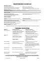
immediately. Follow the Cox Maintenance Schedule & the
engine owner’s manual for engine maintenance and repair. If
it is necessary, for any reason, to inspect or repair the hopper
or any part of the machine where a moving part can come in
contact with your body or clothing, stop the machine, allow it
to cool, disconnect the spark plug wire from the spark plug
and move it away from the spark plug before attempting such
inspection or repair.
OPERATION
Whenever you operate your SuperChipper, wearing gloves
and safety glasses is required. If it is necessary to push
material into the inlet hopper, use a wooden stick, DO NOT
use hands or a steel implement. At the end of this section
there are additional cautions. Read and observe them.
The operation of any SuperChipper can result in foreign
objects being thrown into the eyes, which can result in severe
eye damage. Always wear safety glasses, or eye/face shields
during operation of your SuperChipper or, while performing
any adjustments or repairs.
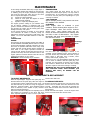
Branches are fed into the inlet hopper for chipping, up to
90mm in diameter or several together if of smaller diameter.
Since the throat opening is 145mm high and 175mm wide,
some side shoots or side branches may have to be trimmed
from the main stalk before chipping. Short stubs of branches
may be pushed through the chipper section with the next
branch. DO NOT assume you know where the blade is and try
to push short branches in by hand. You don’t know where it
is. Be safe, keep your hands away from the chipping blades.
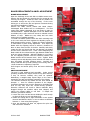
(1) When feeding material into this equipment, be
careful that pieces of metal, glass, rocks, bones, cans
or other non-organic or foreign objects are not
included. Do not feed in root balls as they usually
have soil, sand, grit, stones or other hard or abrasive
materials attached which will damage or blunt the
blades and or other components.
(2) When chipping newspaper only feed 3 to 4
sheets at a time. Putting entire sections in could
damage the rotor.
(3) Do not allow an accumulation of processed
material to build up under the discharge of the
SuperChipper as this can prevent following
chipped material from discharging and will
result in clogging. Use a long handled stick or
spade to remove processed material build-up. D O
NOT USE YOUR HAND OR FOOT. Always shut the
unit off before clearing build-up.
(4) DO NOT allow your hands or any part of your body
or clothing inside the feed hopper or discharge area of
the SuperChipper. Use a wooden stick to push material
down the hopper.
(5) Keep all protective guards on the machine in place
and in good working condition.
(6) Always stand clear of the discharge area when the
SuperChipper is running.


 1
1
 2
2
 3
3
 4
4
 5
5
 6
6
 7
7
 8
8
 9
9
 10
10
 11
11
 12
12
 13
13
 14
14
 15
15
 16
16
 17
17
 18
18
 19
19
 20
20
 21
21
 22
22
 23
23
 24
24


Hyundai HYCH7070 User manual
Hyundai power products HYCH15100TE Wood Chipper Owner's manual
Bushranger BRC40 User manual
Echo Bear Cat 72620 FAQ
 Wessex HLS-100 Assembly Manual
 Spartan Equipment SE900791 Owner's manual
 Spartan Equipment SE900790 Owner's manual
Carlton 1260 Owner's manual
Woods Equipment 8000 User manual


