Page is loading ...

SERVICE MANUAL
DATA
COMPACT DISC
STEREO SYSTEM
BASIC TAPE MECHANISM : 2ZM-1 R9NM
BASIC CD MECHANISM : ZZG-4 YB
XR-M700
K
S/M Code No. 09-009-430-8S1
SUPPLEMENT
• This Service Manual contains the additional information “CD MECHANISM
DISASSEMBLY INSTRUCTIONS” and “CD TEST MODE” for the model
XR-M700 (K).
If requiring the other information, see Service Manual of XR-M700 (K),
(S/M Code No. 09-006-430-8R1).

– 2 –
1. Procedure of Disassembling the ZZG-4 Mechanism
1-1. Removing the FRAME, MAIN
1) Remove a screw and PLATE, FRAME L.
2) Remove the 2 screws and PLATE, FRAME R.
3) Pull up 1 LEVER, LOCK F, and pull out 2 FRAME,
MAIN toward the front. Turn the GEAR, SLIDER B and
adjust the ELEVATOR to any position except TOP.
CD MECHANISM DISASSEMBLY INSTRUCTIONS

– 3 –
4) Remove the FRAME, MAIN on the L side first. Then lift
up toward the direction of the arrow and remove the
FRAME, MAIN from the BASE.
2) Turn the GEAR, SLIDER B and shift the ELEVATOR to
the TOP position.
3) Pull out the GEAR, TRAY AB and SHAFT, ELEVATOR.
1-2. Removing the GEAR, TRAY AB
1) Remove the 2 screws and HLDR, SHAFT.

– 4 –
1-3. Removing the GEAR, ELEVATOR
1) Remove the GEAR, ELEVATOR.
1-4. Removing the CD MAGAZINE Part
1) Remove the GEAR, TRAY A and B, etc. to make it look
like in the photo.
2) Remove the 2 screws and PWB, TRAY.

– 5 –
3) Remove the claws indicated by the circles in order to
remove the MAGAZINE, TOP. Insert a minus driver into
the gap and remove the MAGAZINE, TOP by lifting it
upward.
4) Remove the MAGAZINE, TOP.
5) Remove the TRAY 1,2,3 and 3 pieces of MAGAZINE by
lifting them up.

– 6 –
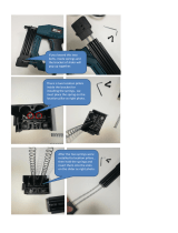
1-5. Removing the ELEVATOR Part
1) Remove the FFC, 4P of the switch circuit board from the
BASE rib, and disconnect it from the connector.
2) 1 Remove the spring (88-ZG5-292-010).
2 Remove the 2 screws.
3) 1 Remove the front side of the HLDR, LINK R from the
boss, rotate it as shown in the photo.
2 Shift the HLDR, LINK R toward the direction of the
arrow as shown in the photo and remove it.
4) Remove the HLDR, LINK L in the same step as R.

– 7 –
5) Remove the boss of the LEVER, ASSY LINK from the
groove of the LEVER SLIDE (both L and R sides).
6) Remove the spring (88-ZG5-225-010).
7) 1 Use a pair of tweezers to remove the claw below the 2 LEVER, LOCK F. Then pull out the LEVER LOCK F.

– 8 –
8) 1 Lift up the PLATE, ELEVATOR, together with the HLDR, CLAMP.
2 Once lift it up to the TOP position, pull it toward the front side. Then remove the PLATE, ELEVATOR and HLDR, CLAMP.
9) Views after removing the ELEVATOR part and MAGAZINE part.
* At this stage, the mechanism’s pick-up can be changed. Refer to “5. Procedure of Replacing the Pick-up” for details.

– 9 –
1-6. Removing the ELEVATOR UP/DOWN Components.
1) Remove the BELT, SLIDER and BELT, BASE. Then remove the 2 screws, the PULLEY, SLIDER and PULLEY, BASE.
2) Remove the screw and GEAR, SLIDER C.

– 10 –
3) Turn over the CD mechanism and short-circuit the shortland of the pick-up.
4) Desolder M201 and M202. And remove the screw.
Disconnect FFC (3 parts) and remove the CD C.B from the BASE.
screw

– 11 –
5) Views after removing the CD C.B.
Once the claws (indicated by the circles) are pressed, 2 of the GEAR, SLIDER A will come off.

– 12 –
2-1. Removing the Pick-up
1) Turn over the CD mechanism and short-circuit the
shotland (indicated by the circle) at the pick-up.
2. Procedure of Replacing the Pick-up
2) Disconnect the FFC, 16P and FFC, 6P.
3) Remove the 2 pieces of the Washer W-P, 2.08-8-0.5
(87-B10-273-010).

– 13 –
4) Put back the CD mechanism and remove the 2 screws of S-SCREW, MECH HLDR (81-ZG1-254-010).
5) Remove the screw VIT+2-3 (87-571-032-410) and LED PWB together with the holder HLDR PWB LED
(88-ZG5-305-010).
6) Remove the 3ZG-2 mechanism from the BASE.
*
Make sure that not to lose a spring (SPR-C, MECHA (F)) during this operation.
7) Remove the pick-up.

– 14 –
2-2. Peripheral parts of 3ZG-2
Parts Name Parts No. Usage Number
A W-P 2.08-8-0.5 SLIT 87-B10-273-010 4
B W 3-8-0.5 88-ZG5-324-010 2
C CUSH-G MAIN A 83-ZG3-225-010 4
D W-L 3.15-8-0.5 88-ZG5-327-010 2
E SHAFT MECHA 88-ZG5-309-010 2
F SPR-C MECHA 88-ZG5-310-010 2
G S-SCREW MECH HLDR 81-ZG1-254-010 2
H CLR MECH 88-ZG5-320-010 2

– 15 –
2-3. Pick-up installation
1) Install the pick-up to 3ZG-2.
2) Locate the 2 springs (SPR-C, MECH (F)) on the rear side
of the BASE.
3) Pass the SHAFT, MECH (E) of 3ZG-2 through the
above-mentioned springs and insert them into holes.
4) Insert the CLR, MECH (H) into the 2 CUSH-G,
MAIN A (C) on the front side.

– 16 –
5) Install the 2 screws (G) into the CLR, MECHA(H).
6) Turn over the CD mechanism and fix the SHAFT, MECH
(E) with washer.
7) Connect the FFC, 16P and FFC, 6P to the connector.

– 17 –
8) Remove the shortland soldering of the pick-up.
9) Put back the CD mechanism and fixate the holder (with the LED PWB mounted) by screwing it through the holes on the 3ZG-2.
*
Make sure that not to touch the pick-up with the LED circuit board.

– 18 –
3-1. Assembly the ELEVATOR Part
1) Lift up both the LEVER, CATCHER L (in red solid line) and R (in red dotted line) and remove the HLDR, CLAMP.
3. ZZG-4 Mechanism Assembly and Phase Adjustment

– 19 –
2) Fit the A’, B’, and C’ of the HLDR CLAMP to the A, B, and C of the BASE respectively, and set the HLDR, CLAMP into the BASE.
Push the HLDR, CLAMP till it chucks with click.
3) Place the PLATE, ELEVATOR on top of the BASE.

– 20 –
4) Set the boss of the LEVER, ASSY LINK into the groove of the LEVER, SLIDER (on the both sides of L and R).
5) 1 Insert the boss of the LEVER, ASSY LINK R into the hole (O) of the HLDR, LINK R and pull it down.
2 Then rotate it as shown in the photo, in order to set the boss into the hole on the front side of the HLDR, LINK R.
/