Page is loading ...

Installation Instructions for 125 Class Beacons,
STROBE Models
Description
Edwards 125 Class Strobes are UL and cUL listed signaling
appliances rated for NEMA 4X applications. There are two
versions of strobes available: Normal Light Output and High
Light Output. Both types can be either surface or conduit
mounted. A protective wire guard, Cat. No. 125GRD, is also
available.
Electrical Specications
GRAY BASE BLACK BASE
Catalog Number Catalog Number Voltage Current
High Output Strobe - 300,000 Peak Candlepower
125STRH*120A 125STRH*120AB 120V AC 50/60 Hz 0.120A
Maximum capacitor operating temperature (Tc) is 185°F (85°C).
Normal Output Strobe- 175,000 Peak Candlepower
125STRN*1248D 125STRN*1248DB 12 - 48V DC 0.350A
125STRN*120A 125STRN*120AB 120V AC 50/60 Hz 0.100A
125STRN*240A 125STRN*240AB 240V AC 50/60 Hz 0.050A
*Letter in this position designates lens color:
A - amber, B - blue, C - clear, G - green, or R - red
Mechanical Specications
Outdoor Locations
Temperature Ratings ........... -31F to +150F (-35C to +66C)
Installation
WARNING
To prevent electrical shock, ensure that
power is turned off before installing the
Conduit Mounting (Figure 1)
1. Thread the 12" (45.7 cm) signal wire leads through 1/2"
(13mm) conduit into an approved conduit outlet box.
2. Thread the conduit onto the base of the signal.
3. Using wire nuts (not supplied), connect the signal's wire
leads as shown in Figure 1. Polarity must be observed
for DC models. For AC models, polarity is not important.
Panel Mounting (Figure 2)
Note: Whenpanelmountingthebeacon,thesurfaceand
constructiondetailsofthepanelmustbetakeninto
considerationinordertoensurethattheintegrity
oftheoutdoor,NEMA4Xratingisfullymaintained.
Installershouldevaluate.
1. Place the mounting gasket (supplied) over the hole in
the panel and route the signal wires through the gasket
and the hole in the panel.
2. Insert the base through the hole in the panel and screw
the locking nut (supplied), with the raised locking edge
facing the mounting surface, onto the base to secure the
beacon.
3. Using wire nuts (not supplied), connect the signal's wire
leads as shown in Figure 2. Polarity must be observed.
Maintenance
WARNINGS
To prevent electrical shock, ensure
power is turned off before installation or
maintenance.
To avoid risk of injury, install lens before
energizing.
Cleaning
To maintain optimum light visibility, the exterior lens surfaces
should be periodically cleaned with a soft clean cloth us-
ing water and a mild detergent. Disconnect power before
cleaning.
Strobe Tube Replacement
1. Conduit Mounted Modules: Disconnect wiring and, if
necessary, unscrew base from conduit (Figure 1).
Panel Mounted Modules: Disconnect wiring and
remove locking nut that secures the base to the panel
(Figure 2).
2. Remove screws that secure the lens to the base from
bottom of base and remove lens.
CAUTION: Do not touch strobe tube while hot.
P/N 3101651 ISSUE 3
© 2010
http://www.edwardssignaling.com Phone: (800) 336-4206 Fax: (800) 454-2363

P/N 3101651 ISSUE 3
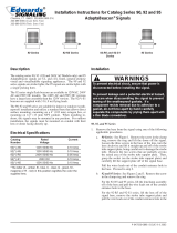
Figure 1. Conduit Mounting (3/4" Shown)
125 Class
Visual Indicator
Connect leads to
Power Source
3/4” NPT external (shown)
1/2” NPT internal
Conduit (not supplied)
DC units; Red positive (+)
AC units; Black Hot
DC units; Black negative (-)
AC units; White neutral
Wire nuts
(not supplied)
18” Wire Leads
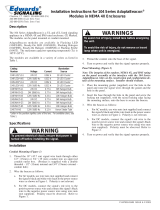
Figure 3. Strobe Tube Replacement
Lens
Strobe Tube
(92-LST strobe tube Shown)
Strobe Socket
O-Ring (in groove)
(supplied)
Base
(4) Screws securiing
lens to base
Table 1. Replacement Parts
GRAY BASE BLACK BASE
Catalog Number Catalog Number
Replacement
Lens Replacement Strobe Tube
High Output Strobe
125STRH*120A 125STRH*120AB 125L* 91B-ST
Normal Output Strobe
125STRN*1248D 125STRN*1248DB
125L*
114-ST
125STRN*120A 125STRN*120AB 91B-ST
125STRN*240A 125STRN*240AB 91B-ST
*Letter in this position indicates lens color: A - Amber, B - Blue, C - Clear, G - Green, R - Red.
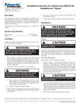
Figure 2. Panel Mounting
125 Class
Visual Indicator
Gasket
(supplied)
Locking Nut -
1.3625" OD
(supplied)
Control panel
(enclosure)
Wire Nuts
(Not Supplied)
18” Wire Leads
Power Source
Wires
/