Step 6 —
Connect
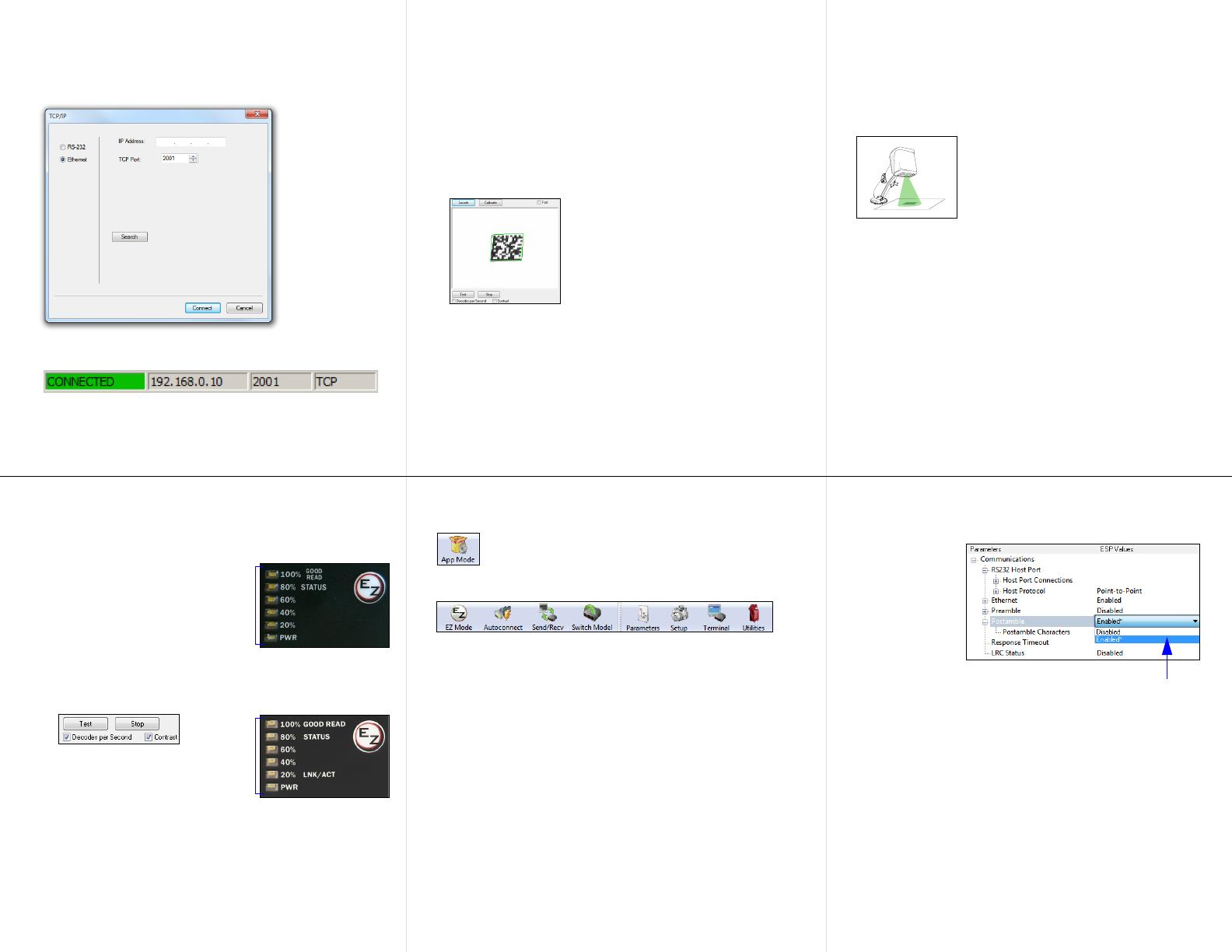
To connect using the Connection Wizard:
• Click Connect on the menu toolbar, and then select Connection Wizard.
• Select the communication interface required by your application.
• Configure settings as required by the application, and click Connect.
• When a connection is established, the green indicator in the status bar at
the bottom right of the screen will be visible:
Important: The imager is in Continuous Read Mode by default. For
best connection results, be sure that no decodable symbols are within the
imager’s field of view while attempting to connect.
Step 9 — Test Read Rate
Read Rate indicates the number of successful decodes per second
achieved by the imager.
Test Read Rate by EZ Button
1. To start the Read Rate test, hold down
the EZ Button about three seconds
until you hear three short beeps. The
20%
,
40%
, and
60%
LEDs will illuminate.
While the object is being inspected, the
Read Rate LEDs will indicate the read
rate percentage on the back of the unit.
2. To end the Read Rate test, press the
EZ Button and quickly release.
Test Read Rate by ESP
1. Click the Test button to start the Read
Rate test and Stop to end it.
If a symbol has been successfully
decoded, its data and related features
will be presented in the field below the
image display window. Also, while the
object is being inspected, the Read
Rate LEDs will indicate the Read Rate
percentage on the back of the unit.
2. To end the test, click the Stop button.
Note: Read Rate can also be tested using the Read Rate interface in
Utilities.
Test Read Rate by Serial Command
You can also start a test with the <C> or <Cp> command and end it with the
<J> command.
MS-4Xi Read Rate
LEDs and EZ Button
MS-4X Read Rate
LEDs and EZ Button
Step 7 — Locate the Symbol
Locate by ESP
•In ESP’s EZ Mode, click the Locate button to enable the blue target
pattern.
The symbol in the field of view will appear in the video view beneath the
Locate
and
Calibrate
buttons, and you will see the blue target
pattern
projected
from the front of the imager.
• Center the target pattern on the symbol.
At 2 to 3 inches, the pattern resembles an X. At 3 to 6 inches, the
pattern resembles a V.
Important: The entire symbol should fall within the field of view (FOV)
of
the imager. The field of view is what appears in
ESP
’s
Locate/Calibrate
window in EZ Mode.
• Click the Stop button to end the Locate function.
Locate by EZ Button
If you are not connected to a host computer, the EZ Button allows you to
locate the symbol in the imager’s field of view.
• Hold down the EZ Button for about one second and release when you
hear one short beep. The amber 20% LED will illuminate, and you will
see the blue target pattern projected from the front of the imager.
• Center the target pattern on the symbol.
Note: To end all EZ Button functions, press the EZ Button once and
quickly release.
Step 10 — Configure and Save
Click the App Mode button to make configuration changes to the imager.
The following modes are accessible by clicking the buttons at the top of the
screen:
• Click the EZ Mode button to return to EZ Mode.
• Click the Autoconnect button to establish communication.
• Click the Send/Recv button to send or receive commands.
• Click the Switch Model button to open the model menu, or to return to
a previous model.
•
Click the
Parameters
button to show the tabbed tree controls for
Communication,
Read Cycle, Symbologies, I/O Parameters, Symbol
Quality, Matchcode, and Diagnostics.
• Click the Setup button to access a Camera Setup tree control and Video
view, Evaluate image captures, Calibrate the imager, set the Window of
Interest, load capture settings and processing settings in the Configuration
Database, set up output filters and parse symbol data in Ordered Output
and Output Format, and control multiple read cycle functions in Dynamic
Setup.
• Click the Terminal button to display decoded
symbol data, and to send
serial commands to the imager using text or macros.
• Click the Utilities button to test Read Rate, request or clear Counters,
enable or disable the imager or send output pulses in Device Control,
determine
the Differences from Default in the current settings, add or
remove master symbol data in Master Database, and verify or update the
imager’s Firmware.
Step 8 — Calibrate
Imager settings can be adjusted automatically for optimum performance
by either the EZ Button or by ESP.
During the calibration routine, the imager will flash its Read Rate
percent LEDs and illumination LEDs while searching camera settings
and determining the best configuration for decoding symbol data. Upon
successful completion
of this routine, a green LED pattern will flash brightly
and illuminate the symbol.
If unsuccessful, the imager will emit 5 short
beeps and stop searching.
Calibrate by EZ Button
1. Hold down the EZ Button for about two seconds and release when
you hear two short beeps. The 20% and 40% LEDs will illuminate.
2.
The imager will search camera settings to determine the best configuration
for decoding symbol data.
Note: To end all EZ Button functions, press the EZ Button once and
quickly release.
Calibrate by ESP
1. Click the Calibrate button.
2.
The imager will search camera settings to determine the best configuration
for decoding symbol data.
A successful calibration will display a green frame around the
symbol,
and the following message will appear: “Uploading all reader
parameters.”
After a moment the symbol data will be presented in
the field below the image display window.
Calibrate by Serial Command
Send <@CAL> from a terminal program to begin calibration.
Step 11 —Save Changes in ESP
To make changes to a configuration setting:
Saving Options
•Send, No Save. Changes will be lost when power is re-applied to the
imager.
•Send and Save. This activates all changes in current memory and
saves to the imager for power-on.
1. Left-click on the
+ to expand the
desired tree.
2. Double-click on
the desired
parameter and
click once in the
selection box to
view options.
3. Place your cursor in the selection box, scroll down to the setting
you want to change, and click once on the setting.
4. Left-click again on the open screen to complete your selection.
5. Right-click on the open screen and select Save to Reader to
implement the command in the imager.


