Page is loading ...

Manual
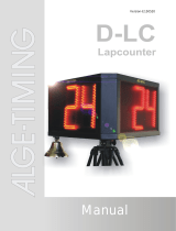
D-LCC Lap Counter
-2-
Important Information
General
Before using your ALGE-TIMING device read the complete manual carefully. It is part of the device and
contains important information about installation, safety and its intended use. This manual cannot cover
all conceivable applications. For further information or in case of problems that are mentioned not at all
or not sufficiently detailed, please contact your ALGE-TIMING representative. You can find contact details
on our homepage https://www.alge-timing.com/
Safety
Apart from the information of this manual all general safety and accident prevention regulations of the
legislator must be taken into account.
The device must only be used by trained persons. The setting-up and installation must only be executed
according to the manufacturer’s data.
Intended Use
The device must only be used for its intended applications. Technical modifications and any misuse are
prohibited because of the risks involved! ALGE-TIMING is not liable for damages that are caused by im-
proper use or incorrect operation.
Power supply
The stated voltage on the type plate must correspond to voltage of the power source. Check all connec-
tions and plugs before usage. Damaged connection wires must be replaced immediately by an author-
ized electrician. The device must only be connected to an electric supply that has been installed by an
electrician according to IEC 60364-1. Never touch the mains plug with wet hands! Never touch live parts!
Cleaning
Please clean the outside of the device only with a smooth cloth. Detergents can cause damage. Never
submerge in water, never open or clean with wet cloth. The cleaning must not be carried out by hose or
high-pressure (risk of short circuits or other damage).
Liability Limitations
All technical information, data and information for installation and operation correspond to the latest
status at time of printing and are made in all conscience considering our past experience and knowledge.
Information, pictures and description do not entitle to base any claims. The manufacturer is not liable
for damage due to failure to observe the manual, improper use, incorrect repairs, technical modifications,
use of unauthorized spare parts. Translations are made in all conscience. We assume no liability for
translation mistakes, even if the translation is carried out by us or on our behalf.
Disposal
If a label is placed on the device showing a crossed out dustbin on wheels (see drawing), the
European directive 2002/96/EG applies for this device.
Please get informed about the applicable regulations for separate collection of electrical and
electronical waste in your country and do not dispose of the old devices as household waste.
Correct disposal of old equipment protects the environment and humans against negative
consequences!
Copyright by ALGE-TIMING GmbH
All rights reserved. Any duplication, either in full or in part, requires the prior written consent of the
copyright holder.

Manual
D-LCC Lap Counter
-3-
Declaration of Conformity
We declare that the following products comply with the requirements of the listed standards.
Parts that we use in the product are CE certificated by the manufacturers and ALGE-TIMING
GmbH does not change them.
We, ALGE-TIMING GmbH
Rotkreuzstrasse 39
A-6890 Lustenau
Declare under our sole responsibility, that the display boards of the type:
D-LCC
produced from 01.01.2005 and later is in conformity with the following standard(s) or other
normative documents(s):
Safety: IEC 60950:1999 / EN 60950:2000
EN 60335-1:2002 + A11:2004 + A1:2004 + A12:2006 + A2:2006
EMC: EN55022:2006+A1:2007
EN55024:1998+A1:2001+A2:2003
EN61000 3-2:2006
EN61000 3-3:1995+A1:2001+A2:2005
Additional Information:
The product herewith complies with the requirements of the Low Voltage Directive 73/23/EEC,
also the EMC Directive 2004/108EG and accordingly carries the CE-marking.
Lustenau, 27.04.2021 ALGE-TIMING GmbH
Albert Vetter
(General Manager)

Manual
D-LCC Lap Counter
-4-
Table of Contents
1 General .......................................................................................................................... 5
2 System Components: ..................................................................................................... 5
3 Power Supply ................................................................................................................. 5
4 Default Setting ................................................................................................................ 5
5 Parameter Setting .......................................................................................................... 6
5.1 Brightness ....................................................................................................... 6
5.1.1 Setting the First Digit ........................................................................................ 6
5.1.2 Setting the Second Digit ................................................................................... 6
5.2 Countdown or Count-Up ................................................................................. 7
5.3 Countdown Start Value .................................................................................... 7
5.4 Display mode and Interface ............................................................................. 7
5.4.1 Display Mode ................................................................................................... 7
5.4.2 Transfer Speed/Protocol .................................................................................. 8
5.5 Power Down Time .......................................................................................... 8
5.6 Address Setting ............................................................................................... 8
6 Functions of Countdown and Count-Up .......................................................................... 8
6.1 Countdown .............................................................................................................. 8
6.2 Count-Up ................................................................................................................. 8
7 Lap Counter Controlled by Timy ..................................................................................... 8
8 RS232 Interface ............................................................................................................. 9
9 Technical Data ..............................................................................................................10
9.1 Powerpack .............................................................................................................10

Manual
D-LCC Lap Counter
-5-
1 General
The display board D-LCC is a lap counter with very flexible functions. Laps can be counted up
or down. Various models of the lap counter are available:
• one-sided, double-sided, triple-sided
• 1 digit per side, 2 digits per side, 3 digits per side
• lap counter with or without bell
2 System Components:
• desired display board (see 1) with built-in powerpack (battery and charging unit)
• controller D-CKA2-LCC
• tripod for lap counter (TRI128 or TRIMAN depending on lap counter model)
• mains cable (to charge the built-in battery)
• possibly bell (depending on lap counter model)
3 Power Supply
The lap counter has an integrated powerpack (battery is installed in the lap counter which can
be connected to the mains for charging (100 - 240 VAC / 50 - 60 Hz).
If the lap counter is connected to mains supply during operation, the internal battery functions
as a buffer battery. This means that the battery takes over in case of a power failure.
The powerpack supplies power for a maximum of 15 hours in continuous use. After a charging
period of 14 hours, the battery is fully charged. The battery can only be charged at tempera-
tures above temperatures of 5°C (41°F).
• green LED: fully charged
• yellow LED: charging
• red LED: battery almost empty
Power Down:
In order to conserve battery power, the lap counter automatically switches to power down mode
after 5 minutes (factory setting). In power down mode, the display switches off. Press the push
button (connected to the green and yellow banana socket) to end the power down mode. The
lap counter automatically displays the last value before the power down mode started.
The duration until the power down mode activates can be set in the menu (parameter , see
point 5.5).
4 Default Setting
A new D-LCC display board has factory settings that are optimized for the device. To restore
these factory settings, press the push button “DOWN/PAR.” of the controller D-CKA2-LCC until
the display shows the version number. This restores all parameters to the factory settings.

Manual
D-LCC Lap Counter
-6-
5 Parameter Setting
There is a menu for setting the parameters of the lap counter:
• brightness
• countdown or count-up
• countdown start value hundreds
• Countdown start value till 99
• format parameter
• power down time
• address of the lap counter
Start the menu by pressing the push button “DOWN/PAR.” for approx. 5 seconds until flashing
is shown. While is flashing, you can switch to the next parameter by pressing the
button “DOWN/PAR.” again. If you wait for about 3 seconds when a parameter is displayed, it
shows the variables of this parameter. As long as a variable is flashing, it can be adjusted with
the button “DOWN/PAR.”.
5.1 Brightness
This parameter is used to adjust the brightness. The first figure (digit) stands for the appear-
ance, the second digit for the brightness.
Factory setting:
5.1.1 Setting the First Digit
The first digit defines the type of switching between two different display modes. The fade in
(fade-in) changes with brightness effects.
Fade-in off
Function is not activated.
Fade-in on
Function is activated. (Brightness is switched on and off at the time of switching)
5.1.2 Setting the Second Digit
This setting defines the brightness of the display.
Manual adjustment
The second position of the brightness setting can be set manually with values between 0 and
9. 0 denotes the minimum, 9 the maximum brightness level. This setting can also be made via
the menu of TDC8001 or TIMY.
Time-dependent brightness
The brightness is adjusted automatically depending on the time of day.
Light-sensitive brightness
With this setting, the brightness of the display depends on the light sensor. If the light sensor
is not connected, the maximum brightness level is set.

Manual
D-LCC Lap Counter
-7-
5.2 Countdown or Count-Up
The factory setting is „Countdown“ starting with a value of 25. If you want to count up, you
have to adjust the counting direction in the menu. The start value is always 0 (zero) for the
count-up.
adjustment for countdown (factory setup)
adjustment for count-up
5.3 and - Countdown Start Value
It is possible to define the value from which the countdown should start. With a 3-digit lap
counter display you can set the hundreds value (0 to 9) with the parameter Ch and the single
and tens values (0 to 99) with the parameter CL. If you set Ch 01 and CL 50, the countdown
starts at 150.
With a 2-digit lap counter there is only the parameter CL and you can set. The lap counter start
value for the countdown mode is possible to define from 0 to 99.
Factory Setting: and
5.4 Display mode and Interface
This setting is required for the interface parameters. The first position of the setting is for the
display mode, the second position for the interface speed (baud rate).
Factory setting:
5.4.1 Display Mode
You can set the various display modes for your display board.
HH:mm:ss (1 sec.)
H:mm:ss.z (1/10 sec.) also speed with 1/10
mm:ss.zh (1/100 sec.)
m:ss.zht (1/1000 sec.)
bib (ID-number), rank
extended mode
The extended mode is used to configure the entire display. You can select which byte is dis-
played at which position of the display. If the serial setting is in this mode, you have several
parameters to set the mode.
The parameters are , , , , … For a detailed description of this function please
see the manual of the D-LINE.
master/slave communication (RS485 or RS232, master=TX, slave=RX) and for
GPS operation! (4800 Baud adjustment = Sen4)
mm:ss.zh (1/100sec.): no function
terminal D-CKN game time (MM:SS, centered) must be 9600 Baud!
!!!D-Line connected by RS232 with D-CKN (Pin5=GND, Pin2=Data)!!!
stop time of day: no function

Manual
D-LCC Lap Counter
-8-
5.4.2 Transfer Speed/Protocol
The second digit of the setting is responsible for the transfer speed of the serial interface.
2400, N, 8, 1 ALGE standard
4800, N, 8, 1 ALGE
9600, N, 8, 1 ALGE
19200, N, 8, 1 ALGE
special format
old devices like the S3, Selftimer SF2
no function
5.5 Power Down Time
This setting defines the time after which the display board changes into the power down mode.
When this is set to 00, the power down mode is off. The time set in power down mode is always
multiplied by a factor of 10 (i.e. 03 would be 30 seconds).
Factory Setting: (300 seconds = 5 minutes)
5.6 Address Setting
To use more than one D-LCC on an addressed protocol, you have to define the addresses of
every single lap counter. Normally, the first line is address 1 , second line address 2
, etc.
6 Functions of Countdown and Count-Up
6.1 Countdown
• connect controller D-CKA2-LCC at the 4-pin Ampenenol connector
• parameter must be set to (see point 5.2).
• parameter : set the start value of the countdown (factory setting = 25).
• press button “DOWN/PAR.”: the value counts down.
• press button “UP”: the value counts up.
• press button “DOWN/PAR.” about 4 seconds: sets the value to the start value
6.2 Count-Up
• connect controller D-CKA2-LCC at the 4-pin Ampenenol connector
• parameter must be set to (see point 5.2)
• start value for count-up is always 0 (zero)
• press button “UP”: the value counts up.
• press button “DOWN/PAR.”: the value counts down.
• press button “DOWN/PAR.” about 4 seconds: sets the value to the start value

Manual
D-LCC Lap Counter
-9-
7 Lap Counter Controlled by Timy
It is possible to control the lap counter from the Timy. In order to do so, select the program
“Commander” and then “Counter”. Now you can set any number desired and confirm with OK.
• Counting up: press <F0>, <F1> or green <OK> button
• Counting down: press <F2>, <F3> or red <OK> button
• Input a number: input number on Timy keypad, press <OK>
Connect the Timy with a banana cable and at the lap counter (display board banana sockets
at Timy to yellow and black banana sockets at lap counter). The baud rate is 2400 baud (pa-
rameter - factory setting).
8 RS232 Interface
It is possible to control the lap counter by RS232 interface.
Connection: yellow and black banana socket
Standard Setting:
• 2400 Baud
• 1 start bit
• 8 data ASCII-Bit
• 1 stop bit
• no parity bit
Protocol:
12345678910 11 12 13 14 15 16 17 18 19 20 21 22 23
bbbbbbbbbbbbbbbbHbZ E b b CR
b blank
H hundred-digit
Z ten-digit
E one-digit
CR Carriage Return

Manual
D-LCC Lap Counter
-10-
9 Technical Data
All connections, switches and status LEDs are on the bottom of the lap counter D-LC.
1 Amphenol plug to connect controller D-CKA2-LCC
2 RS232 connection
3 status LED green – full battery
4 status LED yellow – battery charging
5 status LED red – low battery
6 On/Off-Switch
7 fuse (1.0A)
8 mains 100-240V, 50-60Hz
9.1 Powerpack
Charging time of battery: at least 14 hours at 230 V

Manual
D-LCC Lap Counter
-11-

Manual
D-LCC Lap Counter
-12-
Subject to changes
Copyright by
ALGE-TIMING GmbH
Rotkreuzstr. 39
6890 Lustenau / Austria
www.alge-timing.com
/


