Page is loading ...

AR360
Installation Instructions
25-0081
Page 1 of 2
SCHWEITZER ENGINEERING LABORATORIES, INC.
2350 NE Hopkins Court • Pullman, WA 99163-5603 U.S.A.
Phone: +1.509.332.1890 • Fax: +1.509.332.7990
selinc.com • info@selinc.com
Note: The AR360 must detect a minimum voltage field for normal operation.
Therefore, install the AR360 units at least 2 ft from other line or pole
hardware when applying these units on phase-to-phase system voltages of
7.2 kV or less. In addition, be certain not to install any AR360 units in such a
way as to reduce the insulating air gap between the product surface and any
other conductor sufficiently to initiate a flashover.
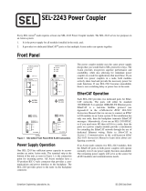
To ensure optimum FCI function, it is best to follow the FCI distance-to-pole recommendations shown in Figure 1.
Figure 1
Reference A: Maximum recommended distance from pole of 6 feet.
Reference B: Minimum distance from pole of 3 feet.
Reference C: Minimum distance from energized hardware of 2 feet.
5.2 in
(13.21 cm)
9.3 in
(24 cm)
3.2 in
(8 cm) 6 in
(15.24 cm)
Before installation, read and understand all instructions in their
entirety. For assistance, please contact Customer Service at
1-847-362-8304 or by email at infolz@selinc.com.
CAUTION
Install in accordance with normal safe operating practices. These instruc-
tions are not intended to replace or supersede existing safety or operating
requirements. Only trained qualified personnel should install or operate
fault indicators and sensors.
FCIs
A
B
Note: Not drawn to scale.
C

25-0081
Page 2 of 2
SCHWEITZER ENGINEERING LABORATORIES, INC.
2350 NE Hopkins Court • Pullman, WA 99163-5603 U.S.A.
Phone: +1.509.332.1890 • Fax: +1.509.332.7990
selinc.com • info@selinc.com
AR360
Installation Instructions
Install the Phase Sensor(s)
Test Activation and Clearing
Note: To remove the fault indicator from the conductor, use an insulated hot stick to grasp the indicator at the molded hookeye on
the face of the indicator. Start pulling the AR360 off until you feel resistance between the spring clamp and the conductor. Then
complete the removal process by applying a twisting motion to the hot stick.
CAUTION
Do not extend the spring
beyond parallel with the
housing, as shown. Over-
extension of the spring
may cause a loss of
clamping force.
Use a hot stick to grasp the
molded hookeye on the face of
the phase sensor.
Position the spring clamp
against the conductor and
retaining bar, as shown.
Position the indicator with the
conductor against the retaining
bar and ensure that the indica-
tor is held in place by the
spring clamp.
1. Remove the shorting bar from the CRSRTT.
2. Place the exposed magnet directly against the product number
AR360 on the label, holding the tool parallel to the label.
3. Hold the tool against the logo for 6 to 8 seconds.
4. Remove the CRSRTT tool. The AR360 will cycle the flash
sequence to demonstrate its activation.
5. Replace the CRSRTT shorting bar for storage.
Spring
Clamp
Conductor
Retaining
Bar
CRSRTT Shorting
Bar
Flash Sequence:
• Red and yellow LEDs
repeat the permanent fault
sequence for 40 seconds.
• Yellow LEDs repeat
single-flash sequences for
20 seconds.
• The unit turns off
automatically.
/