Page is loading ...

SINGLE OVEN DUAL FUEL RANGE
Models: VPFSGE365 ..
INSTALLATION INSTRUCTIONS
IMPORTANT - PLEASE READ AND FOLLOW
• Before beginning, please read these instructions completely and carefully.
• Do not remove permanently affixed labels, warnings, or plates from the product. This may
void the warranty.
• Please observe all local and national codes and ordinances.
• Please ensure that this product is properly grounded.
• The installer should leave these instructions with the consumer who should retain
for local inspector’s use and for future reference.
Installation must conform with local codes or in the absence of codes, the National Fuel Gas
Code ANSI Z223.1/NFPA 54 - Iatest edition. Electrical installation must be in accordance
with the National Electrical Code, ANSI/NFPA70 - latest edition and/or local codes.
IN CANADA: Installation must be in accordance with the current CAN/CGA-B149.1 National
Gas Installation Code or CAN/CGA-B149.2, Propane Installation Code and/or local codes.
Electrical installation must be in accordance with the current CSA C22.1 Canadian Electrical
Codes Part 1 and/or local codes.
INSTALLATION IN MANUFACTURED (MOBILE) HOME: The installation must conform
with the Manufactured Home Construction and Safety Standard, Title 24 CFR, Part 3280
[formerly the Federal Standard for Mobile Home Construction and Safety, Title 24, HUD
(Part 280)] or, when such standard is not applicable, the Standard for Manufactured Home
Installations, ANSI/NCSBCS A225.1, or with local codes where applicable.
INSTALLATION IN RECREATIONAL PARK TRAILERS: The installation must conform with
state or other codes or, in the absence of such codes, with the Standard for Recreational
Park Trailers, ANSI A119.5.
Installation of any gas-fired equipment should be made by a Iicensed plumber. A manual
shut-off valve must be installed in an accessible location in the gas line external to the
appliance for the purpose of turning on or shutting off gas to the appliance (In Massachusetts
such shutoff devices should be approved by the Board of State Examiners of Plumbers &
Gas Fitters).
If an external electrical source is utilized, the appliance, when installed, must be electrically
grounded in accordance with local codes or, in the absence of local codes, with the national
Electrical Code, ANSI/NFPA 70.
R
FOR INSTALLER ONLY
THIS RANGE IS FOR RESIDENTIAL USE ONLY
Some models are supplied with a protective lm on steel and aluminium
parts. This lm must be removed before installing/using the appliance.

2
– Do not store or use gasoline or other ammable vapors and
liquids in the vicinity of this or any other appliance.
– NEVER use this appliance as a space heater to heat or
warm the room. Doing so may result in carbon monoxide
poisoning and overheating of the appliance.
– WHAT TO DO IF YOU SMELL GAS:
• Do not try to light any appliance.
• Do not touch any electrical switch.
• Do not use any phone in your building.
• lmmediately call your gas supplier from a neighbor’s
phone. Follow the gas supplier’s instructions.
• lf you cannot reach your gas supplier, call the re
department.
– Installation and service must be performed by a qualied
installer, service agency, or the gas supplier.
If the information in this manual is not followed exactly,
a re or explosion may result causing property damage,
personal injury, or death.
WARNING !
WARNING
- Slide range back so bolt head, on the adjustable bracket assembly, is
-under anti-tip bracket.
- Look for the anti-tip bracket securely attached to oor or wall.
- See installation instructions for details.
- Look for the adjustable bracket assembly securely attached to
-the back of the range.
- Slide range forward.
To verify the anti-tip bracket is installed and engaged:
Tip-Over Hazard
Anti-tip bracket
Adjustable bracket
assembly to be xed to
the back of the range
A child or adult can tip the range and be killed.
Install anti-tip device to range and/or structure per installation
instructions.
Engage the range to the anti-tip device Installed to the structure.
Re-engage anti-tip device if range is moved.
Failure to follow these instructions can result in death or serious
burns to children and adults.

3
CONVERSION LABEL
DATA PLATE
This appliance is designed and manufactured solely for the cooking of domestic (household)
food and in not suitable for any none domestic application and therefore should not be used in a
commercial environment.
The appliance warranty will be void if the appliance is used within a none domestic environment i.e.
a semi commercial, commercial or communal environment.
WARNING: This product can expose you to chemicals including
formaldehyde, which is known to the State of California to cause cancer,
and lead, which is known to the State of California to cause birth defects or other
reproductive harm. For more information go to www. P65Warnings.ca.gov.

4
Screwdriver 2 - Wrench
T-handle
wrench
Tape
measurePencil
Adjustable
pliers
Adjustable
wrench
Suitable protective
gloves
Drill
Hammer
INSTALLATION INSTRUCTIONS
WARNING!
THIS APPLIANCE MUST BE INSTALLED BY A QUALIFIED INSTALLER.
Installation must conform with local codes.
Improper installation, adjustment, alteration, services, or maintenance can cause injury or property damage. Consult a
qualied installer, service agente or the gas supplier.
TOOLS NEEDED FOR INSTALLATION (NOT SUPPLIED WITH THE APPLIANCE)
IMPORTANT: The use of suitable protective clothing/gloves is
recommended when handling, installing of this appliance.

5
GENERAL INFORMATION
1. Installation must conform with local codes or, in the absence
of local codes, with the National Fuel Gas Code, ANSI
Z223.1/NFPA 54
- Latest Edition, CAN/CGA-B149.1 or CAN/
CGA-B149.2.
2. Installation in manufactured (mobile) home: installation must
conform with the Manufactured Home Construction and
Safety Standard, Title 24 CFR, Part 3280 [formerly the
Federal Standard for Mobile Home Construction and
Safety, Title 24, HUD (Part 280)] or, when such standard
is not applicable, the Standard for Manufactured Home
Installations, ANSI/NCSBCS A225.1, or with local codes
where applicable.
3. Installation in Recreational Park Trailers: installation must
conform with state or other codes or, in the absence of such
codes, with the Standard for Recreational Park Trailers,
ANSI A119.5.
4. To eliminate risk of burns or re by reaching over heated
surface units, cabinet storage located above the surface units
should be avoided.
5. Air curtain or other overhead range hoods, which operate
by blowing a downward air ow on to a range, shall not be
used in conjunction with gas ranges other than when the
hood and range have been designed, tested and listed by an
independent test laboratory for use in combination.
6. WARNING!!
This appliance shall not be used for space heating. This
information is based on safety considerations.
7. AlI openings in the wall behind the appliance and in the oor
under the appliance shall be sealed.
8. Keep appliance area clear and free from combustible
materials, gasoline, and other ammable vapors.
9. Do not obstruct the ow of combustion and ventilation air.
10. Disconnect the electrical supply to the appliance before
servicing.
11. When removing appliance for cleaning and/or service;
A. Shut off gas at main supply.
B. Disconnect AC power supply.
C. Disconnect gas line to the inlet pipe.
D. Carefully remove the range by pulling outward.
CAUTION: Range is heavy; use care in handling.
12. Electrical Requirement
Electrical installation should comply with national and local
codes.
13. Air Supply and Ventilation
The installer must refers to local/national codes.
14. Gas Manifold Pressure
Natural gas - 4.0” W.C.P.
LP/Propane - 11.0” W.C.P.
15. The misuse of oven door (e.g. stepping, sitting, or leaning on
them) can result in potential hazards and/or injuries.
WARNING!!
ELECTRICAL GROUNDING INSTRUCTIONS
The range must be electrically grounded in accordance with
local codes or, in the absence of local codes, with the National
Electrical Code, ANSI/NFPA No. 70-latest edition, in Canada
Canadian Electrical Code.
Installation should be made by a Iicensed electrician.
FOR PERSONAL SAFETY, THIS APPLIANCE MUST BE
PROPERLY GROUNDED.
If an external electrical source is utilized, the installation must be
electrically grounded in accordance with local codes or, in the
absence of local codes, with the national Electrical Code, ANSI/
NFPA 70.
REPLACEMENT PARTS
Only authorized replacement parts may be used in performing
service on the range. Replacement parts are available from factory
authorized parts distributors. Contact the nearest parts distributor
in your area.
16. When installing or removing the range for service, a rolling lift
jack should be used. Do not push against any of the edges of
the range in an attempt to slide it into or out of the installation.
Pushing or pulling a range (rather than using a lift jack) also
increases the possibility of bending the leg spindles or the
internal coupling connectors.

6
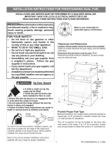
PROXIMITY TO SIDE CABINETS
1. This range may be installed directly adjacent to existing 36”
(914 mm) high base cabinets.
Range dimensions:
• width: 35” 7/8 (911 mm)
• depth: 23” 31/32 (609 mm)
• height (without backguard): MIN 35” 7/16 (900 mm) MAX 37”
13/32 (950 mm)
• backguard
IMPORTANT: the backguard is not packaged with the
appliance but it is supplied separately by the distributor.
Available backguards:
- height = 2” for range depth 25” ½
- height = 3”
- height = 8”
IT IS MANDATORY TO INSTALL THE BACKGUARD.
(911 mm)
35"
7/8
MIN 35" 7/16 (900 mm)
MAX 37"
13/32 (950 mm)
(609 mm)
23"
31/32
(911 mm)
35"
7/8
MIN 35" 7/16 (900 mm)
MAX 37"
13/32 (950 mm)
(609 mm)
23"
31/32
Fig. 1.1a
Fig. 1.1b
Gas line opening:
Wall - 7”
15/32 (190 mm) from the floor; 17” 15/16 (455.5 mm)
from the rear left side to centre of the range.
Grounded outlet: Grounded outlet should be located 17”
15/16
(455.5 mm) from the rear right side to centre of range and from
6”
11/16 (170 mm) to 8” 21/32 (220 mm) [depending on feet
regulation] from the floor.
2. The range CANNOT be installed directly adjacent to sidewalls,
tall cabinets, tall appliances, or other side vertical surfaces
above 36” (914 mm) high.
There must be a minimum of 11” 13/16 (300 mm) side
clearance from the range to such combustible surfaces TO
THE LEFT or TO THE RIGHT above the 36” (914 mm) high
countertop.
IMPORTANT: One side (left or right) above the 36” (914
mm) high countertop must always be kept clear.
Installation with 2" or 3" backguard: There must be a minimum
of 12” (305 mm) clearance from the back of the 2" or 3"
backguard to such combustible surface on the back of the
range above the 36” (914 mm) high countertop.
3. The maximum upper cabinet depth recommended is 13” (330
mm). Wall cabinet above the range must be a minimum of 30”
(762 mm) above the countertop for a width of minimum 35”
7/8 (911 mm): it has to be centred with the range. Side wall
cabinets above the range must be a minimum of 18” (457 mm)
above the countertop.
8" backguard
installation
1
2" or 3" Backguard

7
C
D
B
A
GAS AND ELECTRIC CONNECTION
Dotted line showing the position
of the range when installed
* : Depending on feet regulation
Area for GAS connection
Area for ELECTRICAL
connection
Fig. 1.2
Rif. inch mm
A 7” 15/32 190
B 17” 15/16 455.5
C 6” 11/16 ÷ 8” 21/32
(*)
170 ÷ 220
(*)
D 17” 15/16 455.5
1

8
(457 mm)
18" min.
30" min.
(762 mm)
(914 mm)
36"
0"
(0 mm)
0"
(0 mm)
20" min. (500 mm)
11"
13/16
min. (300 mm)
13" max. (330 mm)
(457 mm)
18" min.
30" min.
(762 mm)
(914 mm)
36"
0"
0"
(0 mm)
(0 mm)
20" min. (500 mm)
11"
13/16
min. (300 mm)
13" max. (330 mm)
OVEN VENT
OVEN VENT
Fig. 1.3b
Fig. 1.3a
PROXIMITY TO SIDE CABINETS
RANGE WITH 8" BACKGUARD
1

9
Fig. 1.3c
Fig. 1.3d
(457 mm)
18" min.
30" min.
(762 mm)
(914 mm)
36"
0"
0"
(0 mm)
(0 mm)
20" min. (500 mm)
13" max. (330 mm)
11"
13/16
min. (300 mm)
12"
min. (305 mm)
(457 mm)
18" min.
30" min.
(762 mm)
(914 mm)
36"
0"
(0 mm)
0"
(0 mm)
20" min. (500 mm)
11"
13/16
min. (300 mm)
13" max. (330 mm)
12"
min. (305 mm)
OVEN VENT
OVEN VENT
1
PROXIMITY TO SIDE CABINETS
RANGE WITH 2" or 3" BACKGUARD

10
Fig. 1.4
FITTING THE ADJUSTABLE FEET
The adjustable feet must be fitted to the base of the cooker before use.
Rest the rear of the cooker on a piece of the polystyrene packaging exposing the base
for the fitting of the feet.
ATTENTION: Most important! Pay special attention not to damage the range dur-
ing this operation.
Fit the 4 legs by screwing them tight into the support base as shown in picture 1.5.
Fig. 1.5
LEVELLING THE COOKER
The cooker may be levelled by screwing the lower ends of the feet IN or OUT (fig. 1.6).
It is important to observe the directions of figure 1.6.
+ 1" 31/32
+ 50 mm
0 mm
0"
Fig. 1.6
Fig. 1.7a Fig. 1.7b Fig. 1.7c
MOVING THE COOKER
WARNING
When raising cooker to upright position always ensure two people carry out this
manoeuvre to prevent damage to the adjustable feet (fig. 1.7a).
WARNING
Be careful: do not lift the cooker by the door handle when raising to the upright
position (fig. 1.7b).
WARNING
When moving cooker to its final position
DO NOT DRAG (fig. 1.7c).
Lift feet clear of floor (fig. 1.7a).
1

11
1
A
A
B
B
Fig. 1.8b
ASSEMBLING THE BACKGUARD
It is mandatory to install the backguard
• Assemble the backguard as shown in figure
1.8a, 1.8b or 1.8c and fix it by screwing the
5 screws “A” (which are already fixed on the
back of the cooktop).
• Fit the no.3 spacers "B" on the rear of the
backguard using the screws and spacers
supplied with the backguard kit.
IMPORTANT: Do not install the range without
the "B" spacers fitted on the backguard.
A
B
A
B
Fig. 1.8a
8" BACKGUARD
3" BACKGUARD
2" BACKGUARD FOR RANGE DEPTH 25" 1/2
Fig. 1.8c
B
A
A
B

12
1
Fig. 1.10
INSTALLING THE ANTI-TIP BRACKET
The anti-tip bracket has two components:
• the adjustable bracket
• the stability bracket
IMPORTANT!
You must install both parts of the anti-tip bracket and ensure they are
properly tted together to prevent the range from tipping.
To t the anti-tip bracket
1. Thread the bolt through the adjustable bracket and x in place using the two supplied nuts.
Exnsure the nuts are well tightened.
2. Fix the adjustable bracket to the back of the range (centered on the lower edge) using the
two supplied screws and washers.
1 2 3
Fig. 1.9

13
1
Fig. 1.11
=
=
Dotted line showing the position
of the range when installed
17”
15/16
(455.5 mm)
Anti-tip stability
device
Adjustable
bracket with
threaded nut
correctly tted
Anti-tip stability
device xing
3. Fix the stability bracket in place. It can be
xed as follows:
• To the oor OR on the rear wall by #4
screws (supplied).
• To the oor AND on the rear wall by #8
screws (supplied).
• There are 8 x wood screws and 8 x
screws with plastic
sleeve anchors supplied with the range
in two separate kits.
Use the proper screws according to
the type of material on the oor and/
or wall.
• If using the the plastic sleeve anchors: drill
5/16” (8mm) diameter holes and insert the
supplied plastic sleeve anchors before
attaching the stability bracket with the
screws.
4. Slide the range into place, ensuring the bolt
on the adjustable bracket slots under the
stability bracket.
• Adjust the length of the bolt as necessary.
Ensure the two nuts are well tightened after
any adjustments.
IMPORTANT!
• Use the proper screws to x the stability
bracket in place
according to the type of material on the
oor and/or wall.
• Before drilling and holes or inserting any
screws into the
oor or wall check that you will not
damage any wiring or
pipes.
WARNING
- Slide range back so bolt head, on the adjustable bracket assembly, is
-under anti-tip bracket.
- Look for the anti-tip bracket securely attached to oor or wall.
- See installation instructions for details.
- Look for the adjustable bracket assembly securely attached to
-the back of the range.
- Slide range forward.
To verify the anti-tip bracket is installed and engaged:
Tip-Over Hazard
Anti-tip bracket
Adjustable bracket
assembly to be xed to
the back of the range
A child or adult can tip the range and be killed.
Install anti-tip device to range and/or structure per installation
instructions.
Engage the range to the anti-tip device Installed to the structure.
Re-engage anti-tip device if range is moved.
Failure to follow these instructions can result in death or serious
burns to children and adults.

14
INSTALLING THE COOKTOP FRONT GUARD (Only for the models without hob rail)
To increase the clearance between the front edge of the cooktop and the burners it is possible to install the cooktop front guard supplied
with the appliance.
IMPORTANT: To install/remove the guard it is necessary to remove the cooktop.
Attempting to install/remove the guard without disassembling the cooktop will result in permanent damage to the appliance.
Install the front guard as shown in gure 1.12:
1. Remove the backguard “A”.
2. Remove the pan supports, the burner caps and the ame spreaders.
3. Unscrew cooktop xing screws (“B” and “C” in gure below).
4. Remove the cooktop (keep attention not to damage the gaskets tted above the burner cups - below the cooktop).
5. Install the front guard “D” by inserting the wire terminals into the proper holes above the control panel (“E” in gure below).
6. Reassemble the cooktop and the other components (steps from 4 to 1).
Pay special attention to the gaskets tted above the burner cups (below the cooktop); if they are damaged they shall be replaced.
C
C
D
E
E
A
B
Fig. 1.12
B
B
B
B
1

15
All gas connections must be made according to national and local codes. This gas
supply (service) line must be the same size or greater than the inlet line of the
appliance. Sealant on all pipe joints must be resistant to te action of LP/Propane gas.
The range is equipped for the use with NATURAL gas. It is design-certified by CSA
International for NATURAL and L.P. gases with appropriate conversion.
The model/serial rating plate, located on the inner side of the storage compartment
pivoting panel, has information on the type of gas that can be used. If this information
does not agree with the type of gas available, check with the local gas supplier. See
page from 21 to 23 for L.P. gas conversion inctructions.
1. Manual Shut-off Valve (fig. 2.1):
A manual shut-off valve must be installed in an accessible location in the gas line
external to the appliance for the purpose of turning on or shutting off gas to the
appliance (In Massachusetts such shutoff devices should be approved by the Board
of State Examiners of Plumbers & Gas Fitters). This valve should be located in the
same room as the range and should be in a location that allows ease of opening and
closing (in a position where it can be reached quickly in the event of an emergency).
Do not block access to the shutoff valve. The valve is for turning on or shutting off
gas to the appliance.
2. Pressure Regulator:
a) All heavy duty, commercial type cooking equipment must have a pressure regulator
on the incoming service line for safe and efficient operation, since service pressure
may fluctuate with local demand.
Before installing the regulator mount the 1/2” NPT (conical) male connector to the
regulator (see picture 2.2a). Gasket supplied has to be placed between 1/2” NPT
(conical) connector/extension pipe male pipe fitting (see picture 2.2b).
The regulator supplied with this range must be installed before any gas connections
are made.
Use supplied pressure regulator only.
b) Assemble the extension pipe + pressure regulator group to the range manifold
interposing the gasket supplied.
2
gas connection
Gas supply line
Shutoff valve
“open” position
To range
Fig. 2.1
Explosion Hazard
Use a new CSA or UL approved
gas supply line.
Install a shut-off valve.
Securely tighten all gas
connections.
If connected to LP, have a
qualified person make sure gas
pressure does not exceed 14”
water column.
Examples of a qualified
person include licensed
heating personnel, authorized
gas company personnel, and
authorized service personnel.
Failure to do so can result in
death, explosion, or fire.

16
PRESSURE REGULATOR INSTALLATION
Arrow
LOCK
STEP 2
Assemble the 1/2” NPT connector + pressure regulator group to the
extension pipe interposing the gasket supplied. The regulator cover must
be ordiented toward the front side of the range.
IMPORTANT: use two spanners to tighten the connection.
Regulator
cover
Fig. 2.2a
Fig. 2.2b
STEP 1
Mount the 1/2” NPT (conical) male connector to the pressure
regulator and tighten by using a wrench.
Do not over tighten the connector.
Over tightening may crack regulator.
2
gasket

17
A
A
STEP 3
Insert the extension pipe + pressure regulator
group in the “A” bracket.
STEP 4
Assemble the extension pipe + pressure
regulator group to the range manifold
interposing the gasket supplied. The
regulator cover must be ordiented toward
the front side of the range.
IMPORTANT: use two spanners to
tighten the connection.
Fig. 2.2c
Fig. 2.2d
2

18
B
B
STEP 5
Fix the “B” bracket on the back of the range by the 2 (two) screws
supplied with the kit for gas connection.
The regulator cover must be ordiented toward the front side of
the range.
Fig. 2.2e
2

19
Connector
Pressure
regulator
1/2” G cylindrical
(ISO 228-1) female
1/2” NPT
(conical)
male
1/2” NPT
female
1/2” NPT
female
1/2” G cylindrical
(ISO 228-1) male
Extension
pipe male
pipe fitting
Gasket
Range
manifold
Manifold male
pipe fitting
1/2” G cylindrical
(ISO 228-1) male
Extension
pipe female
pipe fitting
1/2” G cylindrical
(ISO 228-1) female
Gasket
Extension
pipe
Extension
pipe female
pipe fitting
Arrow
WARNING: check the right
positioning of the gas regulator.
The arrow on the gas regulator must
be oriented toward the connector.
To mains
connection
To range
GAS CONNECTION SPECIFICATION
Fig. 2.3
2

20
Fig. 2.4
TEST POINT ADAPTER
The Test Point adapter is available from
the After-Sales Service.
c) Any conversion required must be performed by your dealer or a qualified licensed
plumber or gas service company. Please provide the service person with this
manual before work is started on the range. (Gas conversions are the responsibility
of the dealer or end user.)
d) This range can be used with NATURAL or LP/PROPANE gas. It is shipped from
the factory adjusted for use with NATURAL gas.
e) Manifold pressure should be checked with a manometer and by operating as
below detailed:
- Remove the injector from the rear left burner and mount the proper test point
adapter which is available from the After-Sales Service (see side figure and the
“OPERATIONS TO BE PERFORMED WHEN SUBSTITUTING THE INJECTORS”
chapter).
- Turn the rear left burner control knob to the maximum position ( position)
- Press the knob and keeping it pressed check the manifold pressure with a
manometer; NATURAL gas requires 4.0” W.C.P. and LP/PROPANE requires
11.0” W.C.P.
- Incoming line pressure upstream from the regulator must be 1” W.C.P. higher
than the manifold pressure in order to check the regulator.
- The regulator used on this range can withstand a maximum input pressure of 1/2
PSI (14.0” W.C.P). If the line pressure is in excess of that amount, a step-down
regulator will be required.
f) The appliance, its individual shut-off valve, and pressure regulator must be
disconnected from the gas supply piping system during any pressure testing of
that system at pressures in excess of 1/2 PSI (3.5 kPa).
g) The appliance must be isolated from the gas supply piping system by closing its
individual manual shut-off valve during any pressure testing of the gas supply piping
system at test pressure equal to or less than 1/2 PSI (3.5 kPa).
3. Flexible Connections:
If local codes permit, CSA or UL design-certified, flexible metal appliance connector is
recommended for connecting this range to the gas supply line. Do Not kink or damage
the flexible connector when moving the range. The pressure regulator has 1/2” NPT
female pipe threads.You will need to determine the fittings required, depending on the
size of your gas supply line, flexible metal connector and shutoff valve.
4. Rigid Pipe Connections:
If rigid pipe is used as a gas supply line, a combination of pipe fittings must be used
to obtain an in-line connection to the range. All strains must be removed from the
supply and fuel lines so range will be level and in line.
• Use joint compounds and gaskets that are resistant to action of natural or propane
gas on all male pipe threads.
• Do not over tighten gas fitting when attaching to pressure regulator. Over tightening
may crack regulator.
5. Leak Testing:
IMPORTANT: Leak testing of the appliance shall be conducted as follows:
• After final gas connection is made, turn on manual gas valve and test all
connections in gas supply piping and appliance for gas leaks with a soapy water
solution. During this test all appliance gas valves have to be closed.
• In order to avoid property damage or serious personal injury, never use a Iighted
match. If a leak is present, tighten joint or unscrew, apply more joint compound,
tighten again and retest connection for leak.
2
/