Preparations
Installation method Description of
installation method
Mount the camera on the two-gang junction box using the attach-
ment plate (accessory). 【Type 1】
Directly mount the camera onto the ceiling or wall using the attach-
ment plate (when wiring can be installed in the ceiling or wall). 【Type 2】
Mount the camera in the ceiling using WV-Q174B ceiling mount
brackets (approx. 280 g {0.62 lbs}).*1
Refer to the Instruction
Manual provided with the
WV-Q174B.
When mounting the camera on an insufciently strong ceiling using
the WV-Q105A ceiling mount brackets
(approximately 150 g {0.33 lbs})
Refer to the Instruction
Manual provided with the
WV-Q105A.
The following notations are used when describing the functions limited for specified models.
The functions without the notations are supported by all models.
:The functions with this notation are available when using the model WV-S2231L / WV-S2131L
/ WV-S2131LRF / WV-S2131LEG / WV-S2131.
:The functions with this notation are available when using the model WV-S2130 / WV-S2110.
:The functions with this notation are available when using the model WV-S2211L / WV-S2111L.
Auxiliary handle MONITOR OUT
conversion plug
4321
External I/O terminal
plug
Power cord plug
Step 2 Remove the enclosure from the camera.
【1】Remove the enclosure and
cushion from the camera.
【2】Remove the power cord plug
(accessory) and the external I/O
terminal plug (accessory)
attached to the camera.
S2131L S2111L
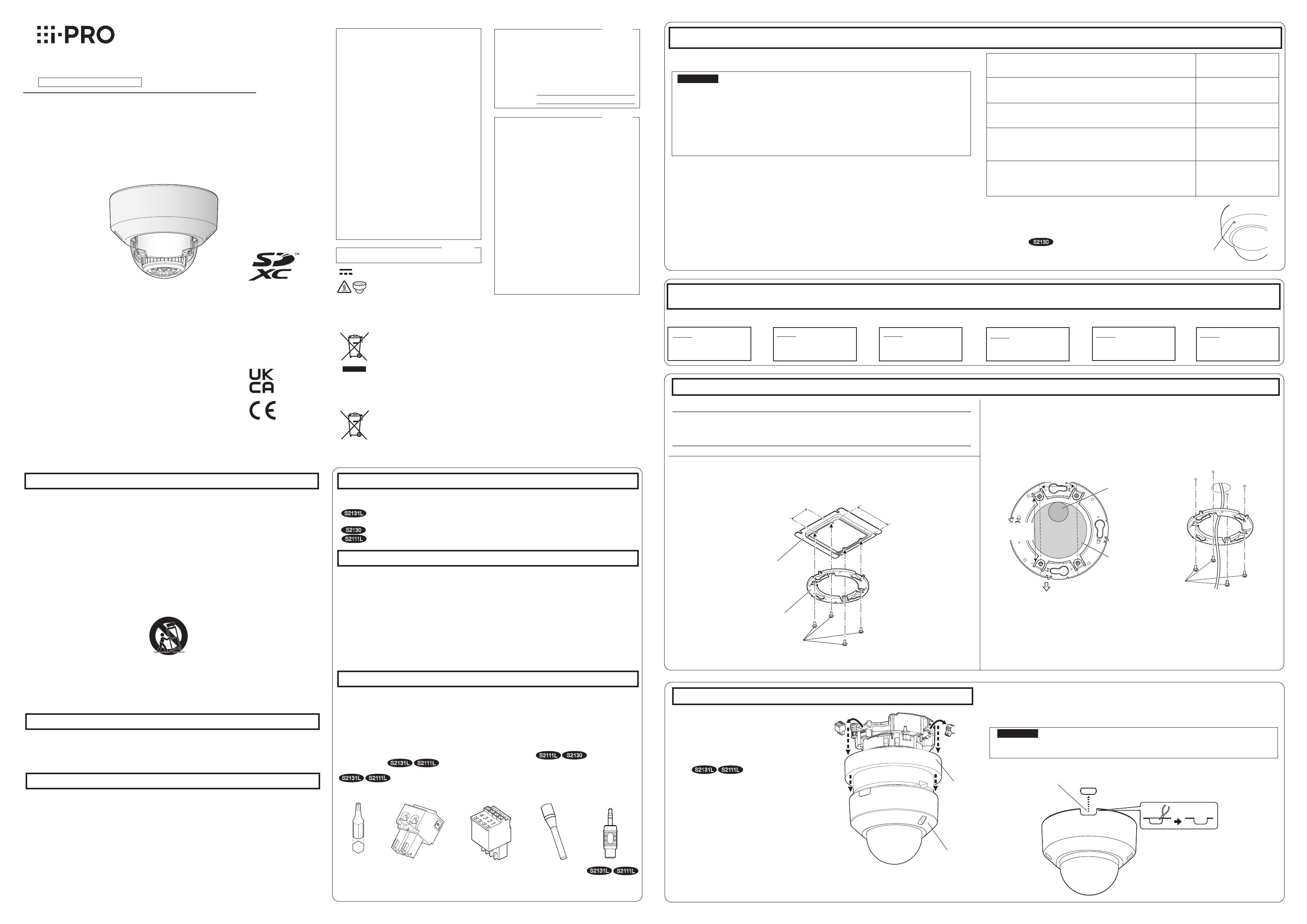
Step 1 Fixing the attachment plate *There are 2 methods to install the camera to a ceiling or wall.
【Type 1】Mount the camera on the two-gang junction box using the attachment
plate (accessory).
Align the FRONT direction of the template A (accessory) with the desired direction, and
drill through a 25.4 mm {1 inch} diameter hole to attach the attachment plate. Then, the
direction of the marker “FRONT⇩” on the camera (see the figure in [3] of “Step 4 Mount
the camera”) should face the desired direction of the camera.
*1
If the mounting direction of the camera is not determined yet or if you want to change
the direction of the camera after it has been installed
If you want to be able to change the direction of the camera, drill through a 73 mm {2-7/8 inches} diame-
ter hole in the center. By doing so you can adjust the mounting direction of the camera in 90° increments.
46 mm
FRONT
ø25.4 mm
{ø1 inch}
ø73 mm*1
{
ø
2-7/8 inches}
83.5 mm
{3-9/32 inches}
46 mm
{1-13/16 inches}
*1 When using WV-Q174B camera ceiling mount bracket, if the built-in
microphone port is blocked by the cover of bracket, the collectable
volume may decrease and the sound of attic is likely to be collected
by mistake. Therefore, please conrm the installation conditions
before use.
WV-S2131L
Built-in microphone port
Network Camera
Model No. WV-S2231L / WV-S2211L
WV-S2131L / WV-S2131LRF
WV-S2131LEG / WV-S2131
WV-S2130 / WV-S2111L / WV-S2110
Installation Guide
Included Installation Instructions
Important safety instructions
1) Read these instructions.
2) Keep these instructions.
3) Heed all warnings.
4) Follow all instructions.
5) Do not use this apparatus near water.
6) Clean only with dry cloth.
7)
Do not block any ventilation openings. Install in accordance with the manufacturer's instructions.
8)
Do not install near any heat sources such as radiators, heat registers, stoves, or other apparatus (including
amplifiers) that produce heat.
9) Only use attachments/accessories specified by the manufacturer.
10) Use only with the cart, stand, tripod, bracket, or table specified by the manufacturer, or sold with the
apparatus. When a cart is used, use caution when moving the cart/apparatus combination to avoid injury
from tip-over.
S3125A
11) Unplug this apparatus during lightning storms or when unused for long periods of time.
12) Refer all servicing to qualified service personnel. Servicing is required when the apparatus has been dam-
aged in any way, such as power-supply cord or plug is damaged, liquid has been spilled or objects have
fallen into the apparatus, the apparatus has been exposed to rain or moisture, does not operate normally,
or has been dropped.
Troubleshooting
Open Source Software
This product contains open source software licensed under GPL (GNU General Public License),
LGPL (GNU Lesser General Public License), etc.
Customers can duplicate, distribute and modify the source code of the software under license of
GPL and/or LGPL.
Refer to the “readme.txt” file on the provided CD-ROM for further information about open source
software licenses and the source code.
Please note that we shall not respond to any inquiries regarding the contents of the source code.
The model number and serial number of this
product may be found on the surface of the unit.
You should note the model number and serial
number of this unit in the space provided and
retain this book as a permanent record of your
purchase to aid identification in the event of
theft.
Model No.
Serial No.
NOTE: This equipment has been tested and found
to comply with the limits for a Class A digital
device, pursuant to Part 15 of the FCC Rules.
These limits are designed to provide reasonable
protection against harmful interference when the
equipment is operated in a commercial environ-
ment. This equipment generates, uses, and can
radiate radio frequency energy and, if not installed
and used in accordance with the instruction man-
ual, may cause harmful interference to radio com-
munications.
Operation of this equipment in a residential area is
likely to cause harmful interference in which case
the user will be required to correct the interfer-
ence at his own expense.
FCC Caution: To assure continued compliance,
(example - use only shielded interface cables
when connecting to computer or peripheral devic-
es). Any changes or modifications not expressly
approved by the party responsible for compliance
could void the user’s authority to operate this
equipment.
For U.S.A.
For U.S.A.
CAN ICES-3(A)/NMB-3(A)
For Canada
WARNING:
• To prevent injury, this apparatus must be secure-
ly attached to the wall/ceiling in accordance with
the installation instructions.
• To prevent fire or electric shock hazard, do not
expose this apparatus to rain or moisture.
• The apparatus should not be exposed to drip-
ping or splashing.
• All work related to the installation of this product
should be made by qualified service personnel
or system installers.
• The installation shall be carried out in accor-
dance with all applicable installation rules.
• The connections should comply with local elec-
trical code.
• Batteries (battery pack or batteries installed)
shall not be exposed to excessive heat such as
sunlight, fire or the like.
CAUTION:
• Any changes or modifications not expressly
approved by the party responsible for compli-
ance could void the user’s authority to operate
the equipment.
• The network camera is only intended for a con-
nection to an ethernet or PoE network without
routing to the outside plant.
Disposal of Old Equipment and Batteries
Only for European Union and countries with recycling systems
These symbols on the products, packaging, and/or accompanying documents mean that used
electrical and electronic products and batteries must not be mixed with general household waste.
For proper treatment, recovery and recycling of old products and used batteries, please take them
to applicable collection points in accordance with your national legislation.
By disposing of them correctly, you will help to save valuable resources and prevent any potential
negative effects on human health and the environment.
For more information about collection and recycling, please contact your local municipality.
Penalties may be applicable for incorrect disposal of this waste, in accordance with national
legislation.
Note for the battery symbol (bottom symbol)
This symbol might be used in combination with a chemical symbol. In this case it complies with the
requirement set by the Directive for the chemical involved.
About the user manuals
Product documentation is composed of the following documents.
• Installation Guide (this document): Explains installation, mounting, cable connections, and adjusting the
eld of view. This manual uses the WV-S2111L as an example in the explanations.
• Important Information (included in the CD-ROM):
Provides basic information about the product.
• Operating Instructions (included in the CD-ROM): Explains how to perform the settings and how to
operate this camera.
Adobe® Reader® is required to read these operating instructions on the provided CD-ROM.
When the Adobe Reader is not installed on the PC, download the latest Adobe Reader from the Adobe web site
and install it.
The external appearance and other parts shown in this manual may differ from the actual product within the
scope that will not interfere with normal use due to improvement of the product.
About notations
Standard accessories
Installation Guide (this document) ........................1 set
IMPORTANT SAFETY INSTRUCTIONS ............... 1 pc.
CD-ROM*1 .......................................................... 1 pc.
Code label*2........................................................ 1 pc.
*1 The CD-ROM contains the operating instructions and different kinds of tool software programs.
*2 This label may be required for network management. Use caution not to lose this label.
The following parts are used during installation procedures.
Attachment plate ................................................ 1 pc.
Template A (for the attachment plate)
......................1 sheet
Power cord plug*3 ............... 1 pc.
External I/O terminal plug*3
............................................... 1 pc.
MONITOR OUT conversion plug ......................... 1 pc.
Auxiliary handle .................. 1 pc.
Bit (WV-S2231L/WV-S2211L only)
(Hex wrench, screw size 6.35 mm {1/4 inches} T10)
.... 1 pc.
S2131L S2111L
S2131L S2111L
S2111L S2130
S2131L S2111L
*3 The external I/O terminal plug and power cord plug are attached to the camera.
Prepare the required parts for each installation method before starting the installation. The following
are the requirements for the various installation methods.
IMPORTANT:
Procure 4 screws (M4) to secure the attachment plate (accessory) to a ceiling or a wall.
The minimum required pull-out capacity of a single screw or anchor bolt is 196 N {44 lbf} or
more when mounting with the installation method
【Type 1】
or
【Type 2】
described in the
right table.
Select screws according to the material of the location that the camera will be mounted to.
In this case, wood screws and nails should not be used.
If the mounting location such as plaster board is too weak to support the total weight, the
area shall be sufficiently reinforced.
Installation
Step1
Fixing the attachment
plate
Step2
Remove the enclosure
from the camera.
Step3
Making connections
⇨⇨
Step5
Adjustment
⇨
Step4
Mount the camera
⇨
Step6
Configure the network
settings
⇨
Remove the camera using the reverse order of the installation procedures.
The installation tasks are explained using 6 steps.
【Type 2】Directly mount the camera onto the ceiling or wall using the
attachment plate (accessory).
46 mm {1-13/16 inches} 83.5 mm {3-9/32 inches}
Two-gang junction box
Attachment plate (accessory)
Fixing screws for attachment plate: x4
(M4, locally procured)
Attachment plate (accessory)
Fixing screws for
attachment plate: x4
(M4, locally procured)
Enclosure
External I/O
terminal
plug
Power
cord
plug
WV-S2231L / WV-S2211L
Do not remove the auxiliary wire.
Using the side cable access hole
When installing the camera directly on the ceiling or wall with cables exposed, or when mounting
the camera using the ceiling mount bracket WV-Q174B (option), cut out a portion of the dome
cover to open a cable access hole.
IMPORTANT:
To prevent injuries and protect the cables, finish the side cable access hole with a file
to avoid sharp edges.
Side cable access hole
Before requesting service, refer to the Important Information (included in the CD-ROM) and
“Troubleshooting” in the Operating Instructions (included in the CD-ROM) and confirm the
trouble.
Cushion
Bit
: Direct current symbol
Note:
Attach the attachment plate (accessory) so that the marking (part number) faces toward
the ceiling or wall to be installed.
【Common】
Before attempting to connect or operate this product, please read these instructions carefully and
save this manual for future use.
For information about the basic description of this product, refer to the Important Information on
the provided CD-ROM. For information about how to perform the settings and how to operate the
camera, refer to the Operating Instructions on the provided CD-ROM.
The model number is abbreviated in some descriptions in this manual.
: Hot surface symbol
© i-PRO Co., Ltd. 2022 Ns1016-8042 PGQX2085RA Printed in China
For U.S. and Canada:
i-PRO Americas Inc.
https://www.i-pro.com/
For Europe and other countries:
i-PRO Co., Ltd. Fukuoka, Japan
https://www.i-pro.com/
i-PRO EMEA B.V. UK Branch
1010 Cambourne Business Park,
Cambridgeshire CB23 6DP
Authorised Representative in EU:
i-PRO EMEA B.V.
Laarderhoogtweg 25, 1101 EB
Amsterdam, Netherlands

