Renogy B07Z4GSYC2 User guide

Type
User guide

This manual is also suitable for

VERSION A0
DC-DC Battery Charger
REGO
12V
60A
QUICK GUIDE
input output
DC-DC Battery Charger
Contents
Package Contents •••••••••••••••••••••••••••••••••••••••••••••••••••••••••••••••••••••••••••••••••••••••••••••••••••••••••••••••• 01
Wiring Diagram •••••••••••••••••••••••••••••••••••••••••••••••••••••••••••••••••••••••••••••••••••••••••••••••••••••••••••••••••••••• 02
Product Overview ••••••••••••••••••••••••••••••••••••••••••••••••••••••••••••••••••••••••••••••••••••••••••••••••••••••••••••••••• 03
Installation •••••••••••••••••••••••••••••••••••••••••••••••••••••••••••••••••••••••••••••••••••••••••••••••••••••••••••••••••••••••••••••••• 04
LED Indicators ••••••••••••••••••••••••••••••••••••••••••••••••••••••••••••••••••••••••••••••••••••••••••••••••••••••••••••••••••••••• 14
Communication ••••••••••••••••••••••••••••••••••••••••••••••••••••••••••••••••••••••••••••••••••••••••••••••••••••••••••••••••••••• 15
Operation & Maintenance ••••••••••••••••••••••••••••••••••••••••••••••••••••••••••••••••••••••••••••••••••••••••••••••••• 18
01
input output
DC-DC Battery Charger
Quick Guide × 1
Renogy Temperature
Sensor × 1
(Model: RTSCC)
IGN Signal Wire × 1 Screws × 4
VERSION A0
DC-DC Battery Charger
REGO
12V
60A
QUICK GUIDE
input output
DC-DC Battery Charger
Package Contents
02
Starting Battery or DC Generator Service Battery System
+
Negative
Positive
input
output
DC-DC Battery Charger
+
zThis Quick Guide contains important installation, operation, and maintenance instructions for
REGO 12V 60A DC-DC Battery Charger. Please read the Quick Guide carefully before using.
zIllustrations in the Quick Guide are for reference only.
zFor more detailed instructions, please refer to the user manual at renogy.com.
zFor additional support, please contact our customer service through renogy.com/contact-us/.
Wiring Diagram
03
input output
DC-DC Battery Charger
IGN
CAN CAN
BVS BTS
DC-DC Battery Charger
input output
DC-DC Battery Charger
31 14
91165 10 127 8 9
2
No. Part No. Part
1 Mounting Holes 7 Negative Output Terminal
2 Fault Status Indicator 8 Positive Output Terminal
3 Battery Status Indicator 9 CAN Communication Ports
4 Battery Type Setting Knob 10 IGN Signal Wire Port
5Positive Input Terminal 11 BVS (Battery Voltage Sensor) Port
6Negative Input Terminal 12 BTS (Battery Temperature Sensor) Port
zPlease inspect the battery charger for any visible damage including cracks, dents,
deformation, and other visible abnormalities before installation.
zThere are no user serviceable parts inside the battery charger. Do not disassemble or attempt
to repair it.
Product Overview
04
Recommended Components
Battery Scenario A: REGO Battery Kit
Renogy REGO Lithium Battery Renogy REGO System Combiner Box
Battery Adapter Cable (output) ( Anderson
PP75 to Anderson 120 Adapter Cable )
Battery Adapter Cable (input) ( Anderson
PP75 to Ring Terminal Adapter Cable )
Anderson PP75
Anderson 120
Battery Scenario B: Normal Battery Kit
Normal Battery with +/- Bolts
Battery Adapter Cables (input / output)
( Anderson PP75 to Ring Terminal
Adapter Cable )
+
-
Installation
0505
Installation
*Optional Accessories
*Battery Fuse (80A) *Fuse Cable *Battery Voltage Sensor
(Model: RVSCC)
Required Tools
Wrench (10mm) Wrench (14mm) Measuring Tape Insulation Tape
10mm
10mm
10mm
14mm
14mm
14mm
3
4
5
6
0606
Installation
Mounting Location
zRisk of explosion! Never install the battery charger in a sealed enclosure with flooded
batteries! Do not install in a confined area where battery gases can accumulate.
zPlace the battery charger on a vertical surface protected from direct sunlight, high
temperatures, and water. Make sure there is good ventilation.
zThe battery charger requires at least 6 inches (150mm) of clearance above and below for
proper air flow. Ventilation is highly recommended if mounted in an enclosure.
zIf the Battery Adapter Cable or Solar Panel Extension Cable is not long enough, you can use
more extension cables or reselect the position where the battery charger needs to be secured.
DC-DC Battery Charger
STEP-1.1
≥150mm
≥5.91inch
≥150mm
≥5.91inch
DC-DC Battery Charger
STEP-1.2
Confirm the installation
location.
Measure the length of the cables connecting to the battery and
solar panel so they can be connected to the battery charger.
0707
Installation
Battery Charger Wiring
zPlease refer to the user manual of the battery charger at renogy.com for the recommended
wire gauge and length.
zPlease make sure that the connections of the Anderson connectors are tight and secure.
input output
DC-DC Battery Charger
STEP-2.1
REGO Battery Kit
Normal Battery Kit
STEP-2.2
For the Output terminal, align the Battery Adapter Cable's
Anderson PP75 connectors to the correct orientation and
polarity.
Bind the Anderson PP75
connectors by sliding the side
grooves.
output
DC-DC Battery Charger
STEP-2.3
input output
DC-DC Battery Charger
input
STEP-2.4
Insert the Anderson PP75
connectors into the Output
terminal.
For the Input terminal, align the Battery Adapter Cable's
Anderson PP75 connectors to the correct orientation and
polarity.
STEP-2.5
input output
DC-DC Battery Charger
STEP-2.6
Bind the Anderson PP75
connectors by sliding the side
grooves.
Insert the Anderson PP75 connectors into the Input terminal.
0808
Installation
Service Battery Wiring
zPlease read the user manual of the service battery carefully before installation.
zIdentify the polarity (positive and negative) on the cables used for the batteries. A reverse
polarity contact may damage the unit.
zSelect a suitable wrench or other tool when tightening the battery bolts to their rated
specification.
zPlease ensure that the Anderson connectors are fully seated and/or the ring terminals are
securely connected.
Battery Scenario A: REGO Battery Kit
zPlease read the user manual of System Combiner Box carefully before wiring.
zIf the devices are connected to the Anderson connectors of the System Combiner Box, please
install a 160A NH fuse in the top NH fuse disconnect switch.
zIf the Anderson PP75 to Ring Terminal Adapter Cable is used to connect with the System
Combiner Box, please refer to the user manual of REGO 12V 60A DC-DC Battery Charger at
renogy.com for more detailed instructions.
zIf positive/negative busbars are used to connect with the normal service battery, please
refer to the user manual of REGO 12V 60A DC-DC Battery Charger at renogy.com for more
detailed instructions.
input output
DC-DC Battery Charger
Output
STEP-3.1
Insert the Anderson 120
connector of the Battery
Adapter Cable (output) to the
System Combiner Box.
0909
Installation
Battery Scenario B: Normal Battery Kit
input output
DC-DC Battery Charger
Output -
+
-
12
12
-
-
STEP-3.2
STEP-3.3
input output
DC-DC Battery Charger
Output +
Attach the ring terminal of
the negative Battery Adapter
Cable (output) to the negative
battery bolt and tighten with a
wrench.
For your safety, it is recommended to use a battery fuse (80A).
Connect the positive Battery Adapter Cable (output) to one
end of the battery fuse, and then connect the other end to the
positive bolt of the battery.
+
-
+
+
+
STEP-3.4
+
Attach the ring terminal of
the positive Battery Adapter
Cable (output) to the positive
bolt of the service battery and
tighten with a wrench.
Battery Indicator
DC-DC Battery Charger
STEP-3.5
Once the battery wiring is completed correctly and the battery
is turned on, the battery charger's Battery indicator lights up
green.
If the Battery indicator does not light up, please refer to the user
manual of the battery charger at renogy.com for troubleshooting
instructions.
1010
Installation
Input Wiring
The battery charger input terminal can be directly connected to the vehicle's starting battery or
DC generator. If you want to wire directly to the DC generator, please refer to the user manual of
REGO 12V 60A DC-DC Battery Charger at renogy.com for more detailed instructions.
zPlease check the vehicle's manual to identify the generator type before connecting. If you
cannot identify the generator type, please refer to the user manual of battery charger at
renogy.com for more detailed instructions.
zThe starting voltage of the battery charger input terminal depends on the generator type. If
it is a smart generator, the starting voltage should be greater than 12.5V; if it is a traditional
generator, the starting voltage should be greater than 13.5V.
zIdentify the polarity (positive and negative) on the cables used for the batteries. A reverse
polarity contact may damage the unit.
zSelect a suitable wrench or other tool when tightening the battery bolts to their rated
specification.
zPlease ensure that the ring terminals are securely connected.
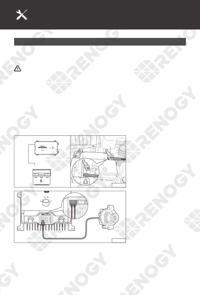
Input -
STEP-4.1
-
-
input output
DC-DC Battery Charger
Attach the ring terminal of
the negative Battery Adapter
Cable (input) to the negative
bolt of the starting battery.
IGN
CAN CAN
BVS BTS
STEP-4.2
IGN
CAN CAN
BVS BTS
If the DC generator of the
vehicle is a smart generator,
insert the IGN Signal Wire
connector into IGN signal
wire port, and then connect
the other end to the smart
generator's ignition signal
port.
1111
Installation
Input +
STEP-4.3
input output
DC-DC Battery Charger
For your safety, it is
recommended to use a
battery fuse (80A). Connect
the positive Battery Adapter
Cable (input) to one end of
the battery fuse, and then
connect the other end to the
positive bolt of the starting
battery.
+
STEP-4.4
+
Attach the ring terminal of
the positive Battery Adapter
Cable (input) to the positive
bolt of the starting battery
and tighten with a wrench.
DC-DC Battery Charger
STEP-4.5
After waiting for 15S, the Battery indicator flashes green and
the battery charger starts to work.
If the Battery indicator does not light up, please refer to the user
manual of the battery charger at renogy.com for troubleshooting
instructions.
1212
Installation
Mounting
zPlease make sure that the battery charger is installed firmly to prevent it from falling off.
DC-DC Battery Charger
STEP-5.1
Place the battery charger
against a flat surface and
secure it with included
screws.
Temperature Sensor
zThe temperature sensor can detect the battery's temperature and update it to the battery
charger for charging voltage calibration. This ensures the battery charger (with operating
temperature range from -20°C to 60°C or -4°F to 140°F) can charge the battery normally.
zDo not use the temperature sensor on a LiFePO4 (LFP) battery which comes with a battery
management system (BMS).
zPlease refer to the user manual of battery charger at renogy.com for more matters needing
attention.
IGN
CAN CAN
BVS BTS
IGN
CAN
BVS BTS
STEP-6.1
+
-
STEP-6.2
Insert the temperature sensor terminal block into the BTS port
of the battery charger.
Adhere the sensor on the
top or side of the battery with
insulation tape.
1313
Installation
*Voltage Sensor (Optional)
The Battery Voltage Sensor is the perfect solution by providing an accurate battery voltage to the
battery charger and allowing it to adjust the charging stage precisely resulting in overall extension
of your battery life.
zIdentify the polarity (positive and negative) on the cables used for the batteries. A reverse
polarity contact may damage the unit.
zThe voltage sensor ring terminal is M8 (Approx. 5/16"). If the battery bolt size is small, please
use a gasket to fix it to prevent it from falling off.
IGN
CAN CAN
BVS BTS
DC-DC Battery Charger
IGN
CAN
BVS BTS
STEP-7.1
Insert the voltage sensor
terminal block to the BVS
port.
+
-
+
-
REGO Battery
Normal Battery
with +/- Bolts
+
-
+
-
+
-
STEP-7.2
Connect the voltage sensor
ring terminal to the positive/
negative pole of the battery
system.
14
Battery Status Indicator
DC-DC Battery Charger
STEP-8.1
DC-DC Battery Charger
STEP-8.2
DC-DC Battery Charger
STEP-8.3
The Battery indicator flashes
green while the service
battery system is being
charged.
Once the service battery
system is fully charged, the
battery charger stops working
and the Battery indicator
lights up green and remains
solid.
When the power of the
starting battery is low,
the battery charger will
automatically reverse charge
the starting battery from the
service battery system, and
the Battery indicator lights up
blue and remains solid.
Fault Status Indicator
DC-DC Battery Charger
STEP-8.4
DC-DC Battery Charger
STEP-8.5
Under normal conditions, the
Fault indicator will not light
up.
If the Fault indicator lights up, please refer to the user manual
of the battery charger at renogy.com for troubleshooting
instructions.
LED Indicators
15
The communication connection is optional. The communication between REGO products allows
safe operation, smart control, and close monitoring.
Depending on the installation condition, the communication connection needs to be established
with backbone or daisy chain topology.
Backbone Topology
If an RV-C bus is pre-installed in the RV, please follow the backbone topology for the
communication connection.
Recommended Accessories
LP16 Plug (7-Pin) to Bare Wires Drop Cable Drop Plug
zDifferent drop sockets are used on the RV-C bus by different RV manufacturers. Please select
the Drop Plug that matches the drop socket for the communication connection. If unsure about
the Drop Plug selection, please check with the RV manufacturer. This Quick Guide takes the
Mini-Clamp II plug (4-pin) as an example.
zThe length of the Drop Cable shall not exceed 19.6 feet, and the total length shall not exceed
98.4 feet.
zDifferent Drop Plugs follow different pinouts. Please crimp the Drop Plug to the Drop Cable
following the correct pinout. If unsure about the Drop Plug pinout, please check with the
RV manufacturer. This Quick Guide takes the pinout of the Mini-Clamp II plug (4-Pin) as an
example.
Communication
16
Communication
STEP-9.1
4 3 2 1
STEP-9.2
Insert the bare wires of the Drop Cable (sold
separately) all the way into the wire ports of
the Drop Plug (not included) following the Drop
Plug pinout. The red PS+ wire goes to pin 1,
the white CAN_H wire goes to pin 2, the blue
CAN_L wire goes to pin 3, and the black PS-
wire goes to pin 4.
Squeeze the crimp area of the Drop Plug with
a pair of split joint pliers.
STEP-9.3
Locate the drop tap (not
included) on the RV-C bus
(not included) that is the
closest to the battery charger
installation location. The
drop taps are usually located
above the entry door, in the
bathroom, or under the bed
in the RV.
IGN BVS BTS
DC-DC Battery Charger
STEP-9.4
Connect either of the CAN
Communication Ports of the
battery charger to the drop
socket on the drop tap with
the Drop Cable.
zDifferent drop taps are used on the RV-C bus by different RV manufacturers. This Quick Guide
takes the 4-socket drop tap as an example.
zIf unable to locate the drop taps, please contact the RV manufacturer for help.
zPlease ensure termination at both ends of the RV-C bus with 120Ω resistors (not included).
17
Daisy Chain Topology
If the RV-C bus is not available, please follow the daisy chain topology for the communication
connection.
Recommended Accessories
LP16 Plug (7-Pin) Communication Cable LP16 Terminator Plug (7-Pin)
IGN BVS BTS
DC-DC Battery Charger
STEP-9.5
IGN BVS BTS
DC-DC Battery Charger
STEP-9.6
IGN BVS BTS
Connect REGO devices in
series through either of the
CAN Communication Ports
with the Communication
Cables (sold separately).
Plug the Termionator Plug (sold separately) into the free CAN
Communication Ports on the first and last REGO devices.
Communication
18
Operation
The battery charger is simple and easy to use. The plug & play design makes the installation
easier, and the knob with 5 gears makes the selection of battery type more convenient.
The default battery type of the battery charger is AGM/SLD. After the wiring of the battery charger
output is completed, please manually set the battery type according to the usage needs.
input output
DC-DC Battery Charger
USER mode Lithium Battery Flooded Battery Gel Battery AGM Battery
User Mode requires the addition of the Renogy DC Home app customize charge parameters.
Please scan the QR Code on the last page of the Quick Guide to download the app.
Maintenance
For optimum performance, it is recommended to perform these tasks regularly.
zEnsure the battery charger is mounted in a clean, dry, and ventilated area.
zEnsure there is no damage or wear on the cables.
zEnsure the firmness of the Anderson connectors and check if there are any loose, damaged
or burnt connections.
zMake sure that the Battery indicator and Fault indicator are in normal state.
zEnsure there is no any corrosion, insulation damage, or discoloration marks of overheating or
burning.
zRisk of electric shock! Make sure that all power is turned off before touching the terminals on
the battery charger.
zPlease refer to the user manual of the battery charger at renogy.com for more details.
Operation & Maintenance
  • Page 1 1
  • Page 2 2
  • Page 3 3
  • Page 4 4
  • Page 5 5
  • Page 6 6
  • Page 7 7
  • Page 8 8
  • Page 9 9
  • Page 10 10
  • Page 11 11
  • Page 12 12
  • Page 13 13
  • Page 14 14
  • Page 15 15
  • Page 16 16
  • Page 17 17
  • Page 18 18
  • Page 19 19
  • Page 20 20
  • Page 21 21
  • Page 22 22

Renogy B07Z4GSYC2 User guide

Type
User guide
This manual is also suitable for

Ask a question and I''ll find the answer in the document

Finding information in a document is now easier with AI