daviteq WSLRW-LPC-01 User guide

Type
User guide

The Daviteq WSLRW-LPC-01 is a LoRaWAN sensor with a built-in advanced Lidar sensor to accurately count people walking through a gate in both directions. It utilizes Lidar technology,不受温度、湿度和射频噪声的影响,并且受环境光的影响较小。 It's battery-operated and connects to any LoRaWAN gateways, supporting all frequency zones. Typical applications include people counting in retail stores, offices, and public spaces.

The Daviteq WSLRW-LPC-01 is a LoRaWAN sensor with a built-in advanced Lidar sensor to accurately count people walking through a gate in both directions. It utilizes Lidar technology,不受温度、湿度和射频噪声的影响,并且受环境光的影响较小。 It's battery-operated and connects to any LoRaWAN gateways, supporting all frequency zones. Typical applications include people counting in retail stores, offices, and public spaces.

Thank you very much for choosing Daviteq Wireless Sensors. We are the leading wireless sensor manufacturer in the
World. We have a wide range of wireless sensors which support different connectivity like LoRaWAN, Sigfox, Sub-GHz,
NB-IoT...Please find out more information at this link.
This manual is applied to the following products
Item code
HW Version
Firmware Version
Remarks
WSLRW-LPC-01
1.0
1.0
Information Changes in this version v.s previous version
Item
Changes
Changed by
Changed Date
Approved by
Approved Date
1
Initial version
P.N.Diep
09-05-2022
N.V.Loc
28-05-2022
To use this product, please refer step by step to the below instructions.
Operating Principle
Uplink Payload
Battery
Connect to Gateway
Installation
Troubleshooting
Configuration
Calibration
Specification
Warranty and Support
WSLRW-LPC is a LoRaWAN sensor with a built-in advanced Lidar sensor to detect and count people. It can count the
people walking thru a gate in 2-way with an accuracy higher than 95%. This sensor utilizes lidar technology, which is
not affected by temperature, humidity, and RF noise and is less affected by ambient light...
Manual for LoRaWAN Lidar People
Counter - WSLRW-LPC | FW 1.0
1. Quick Guide
Reading time: 10 minutes
Finish this part so you can understand and put the sensor in operation with the default configuration from the
factory.
1.1 What is the LoRaWAN Lidar People Counter sensor and its
principle of operation?
It is battery-operated and able to connect to any LoRaWAN gateways. It supports all frequency zones.
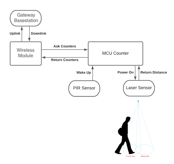
For the principle operation of the Lidar people counter, please refer to this link.
Please refer to this link for typical applications.
In most cases, the device will not send the uplink message immediately when there is a person or object passing thru
the gate, as this operation will cause the battery to drain off quickly.
Instead, it will send uplink messages in the following cases:
For example, every 10 or 30 minutes. In this case, it will send the updated counting values. There are 02 counting
values in the payload:
- Resettable counter.
- Non-resettable counter.
To change the cycle of data sending, you can change the value of the parameter: Cycle send data (default is 900
seconds)
In case, if you want the device to send an uplink message upon a certain number of people passing thru the gate then
you can configure the following parameter: count_threshold. The default value is 20.
What does it mean? It means when the resettable_counter reaches the number 20 (20 people pass thru in one
direction, for any direction), the device will send the uplink message. After sending, it will reset the resettable_counter
to zero for counting again in the next cycle. The count_threshold can be configured to any value from 1.
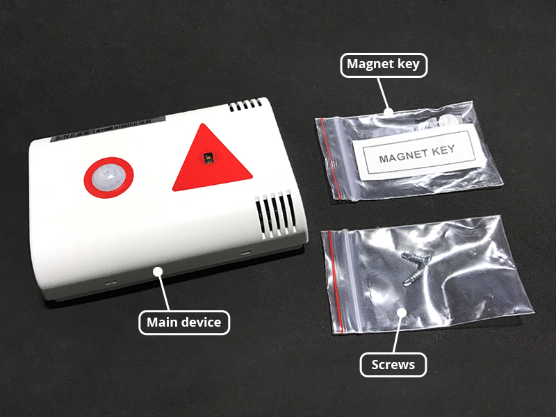
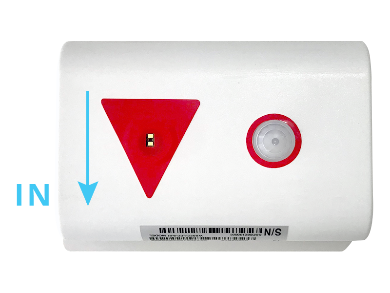
During commissioning the sensor, you can manually trigger the data sending by applying the Magnet key so that the
device will send data immediately.
In summary, the device will send the uplink messages in 03 cases:
- Case 1: when the time of the Data sending cycle is reached.
- Case 2: when the value of the resettable counter is larger than the pre-defined count threshold.
- Case 3: when the device is forced to send data by a Magnet key.
The sensor was pre-configured at the factory with default values for configuration parameters that meet the most use
cases. However, depending on the specific use case, the customer can adjust those parameters. Please refer to
section 3.2 for more details.
1.1.1 What are the typical applications of this sensor?
1.1.2 When does the device send uplink messages?
Case 1: Send an uplink message in the pre-defined cycle
Note: we do recommend using a non-resettable counter.
Case 2: Send an uplink message upon a certain number of people passing thru!
Case 3: Send uplink on demand!
Note: the time interval between the 02 triggers must be larger than 15 seconds.
Send uplink as quickly as possible!
In some special use cases, if you need the device to send an uplink message upon there is a person or
object passing thru the gate, then you need to configure the following parameters:
* Count_threshold = 1
* Sensor_sampling_rate = 10 (10 seconds is smallest value for battery saving)
1.1.3 The important configuration parameters
The sensor is smart, thanks to the integrated PIR sensor. If there were no people around it will fall to the sleep stage to
save battery. If there were people nearby, it will wake up in a very short time and then be ready to count people
passing thru.
The sensor is powered by 6 x AA 1.5V batteries for many years of operation. We do recommend using Energizer L91
battery which is very popular and high performance. This battery has a capacity of up to 3500mAh with a working
temperature range from -40 to +60 oC. The instruction for installing the batteries is in this link.
For Battery life estimation, please refer to this link.
With the default configuration, the device can be connected quickly to the Network Server by the following steps.
Frequency zone
Most of the sensor was configured the frequency-zone to suit customer
application before delivery
DevEUI
Get the DevEUI on the product nameplate
AppEUI
Default value: 010203040506070809
AppKey
Default value: 0102030405060708090A0B0C0D0E0F10
Activation Mode
OTAA with local join server
Network Mode
Public
LoraWAN Protocol version
1.0.3
Class
A
1.1.4 What kind of battery is used for this sensor?
1.2 What's in the package?
The package includes:
01 x Lidar sensor
01 x Magnet key
02 x Self-tapping screw M4
1.3 Quick Test for LoRaWAN Sensor
Step 1: Prepare the values of communication settings:
Note: If the above settings do not match your network server/application, please refer to section 3.2 Sensor
configuration to change the settings
Input the above settings on your device registration page of the network server.
Please visit this link to get the instructions for adding the LoRaWAN sensors to some common network servers such as
Actility, TTN...
Refer to this link for details.
Please refer to section 1.4 Uplink Payload and Data Decoding for details of decoding the receiving packet.
For the Uplink Payload structure, please refer to this link.
Step 2: Register the device on the LoRaWAN network server.
Note: Different network server software will have different processes for registering the device. Please refer to
the manual of the network server software being used for more details.
Step 3: Install the batteries to the device
After installing the battery in 60 seconds, the first data packet will be sent to the LoRaWAN gateway. After
receiving the first data packet, the time of another packet depends on the value of the parameter:
cycle_send_data. Additionally, you can use a Magnet Key to force the device to send data instantly.
Step 4: Decode the payload of receiving package
1.4 Uplink Payload and Data Decoding
Note: Please select the right Payload document to suit the FW version of the sensor
1.5 Sensor Installation
ATTENTION:
- DO NOT INSTALL THE SENSOR OUTDOOR OR INDOORS WITH HIGH-INTENSITY OF SUNLIGHT;
- DO NOT INSTALL THE SENSOR AT A PLACE WHERE HIGH DUST PARTICLES OR STEAM AFFECT THE OPTICAL
SENSOR;
- DO NOT INSTALL THE SENSOR AT A PLACE WHERE THE PEOPLE MOVING IN PARALLEL AND NEARBY THE
SENSOR, THAT WILL CAUSE THE SENSOR TO WAKE UP ALL THE TIME, BUT NOT FOR COUNTING PEOPLE. THIS
PROBLEM WILL MAKE THE BATTERIES DRAIN OFF QUICKLY IN A FEW DAYS.
WARNING:
- Avoid placing hands or heavy objects on the laser sensor surface or the PIR sensor surface, as this may cause
damage to the device;
- Periodically use a clean cloth moistened with 70 degrees of alcohol to wipe the surface of the 2 sensors to keep
the sensor clean and accurate.
DEVICE DIMENSIONS
Then follow this link for instructions on mounting the sensor on the ceiling.
Please follow the instructions in this link.
Depending on the height of installation, the distThreshold parameter may need to change to an appropriate value so
that the sensor can count accurately.
Please follow the steps in this link.
1.5.1 Mounting sensor on the ceiling
Please take note of the direction of people entering the room of the sensor
1.5.2 Battery Installation
1.5.3 Sensor calibration
2. Maintenance
2.1 Troubleshooting
Problems with LoRaWAN communication like not receiving the packets...please refer to this link to
troubleshoot the device.
Problems with the sensor functions like not measuring, or inaccurate measuring....please refer to this link to
troubleshoot the sensor part.
Yes/No
Descriptions
No
The lidar sensor is not a consumable part,
there is no need to replace the sensor module
Yes
Check and clean the surface of the lidar sensor
and PIR sensor. Please refer to this link;
No
The Daviteq LoRaWAN Lidar People Counter comprises 02 parts linked internally as shown below picture.
- The Daviteq LoRaWAN module;
- The Daviteq Lidar People Counter;
The people counting module is working independently from the wireless module. That means while the counting
module is counting people, the wireless module may be in sleep mode to save battery. The wireless module will wake
up and read data from the counting module to check the counting value periodically (120 seconds as default,
configurable) to see whether the counter increase so that it will decide to send a message or not. The 120 s is the
default value of parameter sensor_sampling_rate. You can reduce this value, but smaller value, shorter battery life!
The device will send the uplink messages in 03 cases:
- Case 1: when the time of the Data sending cycle is reached.
- Case 2: when the value of the resettable counter is larger than the pre-defined count threshold.
2.2 Sensor maintenance
3. Advanced Guide
3.1 Operating principle of LoRaWAN Lidar People Counter
3.1.1 Operating principle of the complete device
- Case 3: when the device is forced to send data by a Magnet key.
To understand how Lidar technology can count people, please refer to this link for a complete understanding of this
measuring technique.
Below are some important configuration parameters which affect the operation of the device.
sampling_rate | Default = 120s
The counting module is working independently from the wireless module. That means while the counting module
is counting people, the wireless module may be in sleep mode to save battery. The wireless module will wake up
and read data from the counting module to check the counting value periodically (120 seconds as default,
configurable) to see whether the counter increase so that it will decide to send a message or not. The 120 s is the
default value of parameter sensor_sampling_rate. You can reduce this value, but smaller value, shorter battery
life!
count_threshold | Default = 20
With this threshold, the device will send an uplink message when the resettable_counter reaches this threshold.
After sending, the resettable _counter will be reset to zero again.
distThreshold | Default = 1600mm
Change this parameter to suit the height of the sensor
cycle_send_data | Default = 3600s
Interval time to send an uplink message regardless of any conditions
Those configuration parameters can be changed by downlink or offline tools. For more other configuration parameters,
please refer to the next section.
Sensor configuration can be configured in 02 methods:
Method 1: Configuring via Downlink message. Please find the instructions in this link, but please take note of
the FW version of the Document.
Method 2: Configuring via offline cable.
Some parameters are read-only, and some are read and writeable.
To read the parameters, use the off-line cable as above instruction.
To write the parameters, use the off-line cable or downlink as above instructions.
Below tables are the lists of the parameters of the device.
Read-only Parameter Table
Modbus
Register
(Decimal)
Modbus
Register
(Hex)
Function
Code
# of
Registers
Description
Range
Default
Format
Property
Comment
0
0
3
5
device info
WSLRW-I2C
string
Read
Wireless
Sensor
LoRaWAN -
I2C
5
5
3
4
firmware
version
1.00ddmm
string
Read
ddmm =
day / month
3.1.2 Operating principle of Lidar People Counting Module
3.1.3 Some important configuration parameters
3.2 Sensor Configuration
3.2.1 How to configure the LoRaWAN Lidar People Counter?
Note: THE SENSOR IS ONLY ACTIVE FOR OFFLINE CONFIGURATION IN THE FIRST 60 SINCE POWER UP
BY BATTERY OR PLUGGING THE CONFIGURATION CABLE.
3.2.2 What parameters of the device are configured?
9
9
3
2
hardware
version
1.10
string
Read
11
B
3
4
lorawan
protocol
version
01.01.00
string
Read
LoRaWAN
v1.1.0
15
F
3
6
application
version
01.03.00.00
string
Read
application
server
v1.3.0.0
21
15
3
6
mac layer
version
04.04.02.00
string
Read
mac layer
v4.4.2.0
27
1B
3
4
deviceEUI
hex
Read
End
Device's
EUI
number,
used to
register the
product on
the Network
Server by
OTAA
31
1F
3
4
Lora appEUI
hex
Read
Application
server's EUI
number is
used to
register the
product on
the Network
Server by
OTAA
35
23
3
8
Lora
appKey
hex
Read
The number
of keys
used to
create two
security
keys of the
End Device,
used to
register the
product on
the Network
Server by
OTAA
43
2B
3
8
Lora
nwkSkey
hex
Read
key number
encrypts
the
communication
command
of the MAC
layer of the
End Device,
which is
used to
register the
product on
the Network
Server by
ABP
51
33
3
8
Lora
appSkey
hex
Read
End Device
data
encryption
key
number,
used to
register the
product on
the Network
Server by
ABP
59
3B
3
2
device
address
0
uint32
Read
End Device
address
created by
the
Application
server,
used to
register the
product on
the Network
server by
ABP
61
3D
3
2
network ID
0
uint32
Read
Network
server ID
number,
used to
register the
product on
the Network
server by
ABP
63
3F
3
2
join mode
OTAA
string
Read
OTAA:
Over-the-Air
activation,
ABP:
Activation
by
Personalization
65
41
3
4
network
mode
PUBLIC
string
Read
PUBLIC,
PRIVATE
69
45
3
3
region code
AS923
string
Read
1: AS923, 2:
KR920, 3:
AU915, 4:
US915, 5:
EU868, 6:
IN865, 7:
RU864, 8:
CN779, 9:
CN470, 10:
EU433
72
48
3
4
data rate
DR2:980
string
Read
DR0:250,
DR1:440,
DR2:980,
DR3:1760,
DR4:3125,
DR5:5470
76
4C
3
3
bandwidth
BW125
string
Read
BW125,
BW250,
BW500
79
4F
3
2
spread
factor
SF10
string
Read
SF12, SF11,
SF10, SF9,
SF8, SF7
81
51
3
4
activation
of ADR
ADR OFF
string
Read
ADR ON,
ADR OFF
85
55
3
1
class
A
string
Read
103
67
3
1
sensor type
1-255
uint16
Read
1-254:
sensor
type, 255:
no sensor
104
68
3
1
battery
level
0-3
uint16
Read
4 levels of
battery
capacity
status
Read/Write Parameter Table
Modbus
Register
(Decimal)
Modbus
Register
(Hex)
Function
Code
# of
Registers
Description
Range
Default
Format
Property
Comment
256
100
3 / 16
1
Modbus
address
1-247
1
uint16
R/W
Modbus
address of
the device
257
101
3 / 16
1
Modbus
baudrate
0-1
0
uint16
R/W
0: 9600, 1:
19200
258
102
3 / 16
1
Modbus
parity
0-2
0
uint16
R/W
0: none, 1:
odd, 2:
even
259
103
3 / 16
9
serial
number
string
R/W
(Password)
268
10C
3 / 16
2
password
for setting
uint32
R/W
(Password)
password
190577
Note: Please check the column Property for identifying which parameter request a password for writing a new
value. In this case, the user needs to input the password (190577) into the parameter name "password for
setting" at address 268.
270
10E
3 / 16
4
Lora appEUI
hex
R/W
(Password)
Application
server's EUI
number,
used to
register the
product on
the Network
Server by
OTAA
274
112
3 / 16
8
Lora
appKey
hex
R/W
(Password)
The number
of keys
used to
create two
security
keys of the
End Device,
used to
register the
product on
the Network
server by
OTAA
282
11A
3 / 16
8
Lora
nwkSkey
hex
R/W
(Password)
key number
encrypts
the
communication
command
of the MAC
layer of the
End Device,
which is
used to
register the
product on
the Network
Server by
ABP
290
122
3 / 16
8
Lora
appSkey
hex
R/W
(Password)
End Device
data
encryption
key
number,
used to
register the
product on
the Network
Server by
ABP
298
12A
3 / 16
2
device
address
uint32
R/W
(Password)
End Device
address
created by
the
Application
server,
used to
register the
product on
the Network
server by
ABP
300
12C
3 / 16
2
network ID
uint32
R/W
(Password)
Network
server ID
number,
used to
register the
product on
the Network
server by
ABP
302
12E
3 / 16
1
activation
mode
0-1
1
uint16
R/W
(Password)
1: OTAA
(Over-the-
Air
Activation),
0: ABP
(Activation
by
Personalization)
304
130
3 / 16
1
application
port
1-255
1
uint16
R/W
(Password)
Port 224 is
reserved
for
certification
305
131
3
16
1
network
mode
0-1
1
uint16
1: Public, 0:
Private
317
13D
3 / 16
1
region
1-7
1
uint16
Read/Write(Password)
1: AS923, 2:
KR920, 3:
AU915, 4:
US915, 5:
EU868, 6:
IN865, 7:
RU864, 8:
CN779, 9:
CN470, 10:
EU433
318
13E
3 / 16
1
data rate
7
uint16
R/W
(Password)
0: 250 bps,
1: 440 bps,
2: 980 bps,
3: 1760
bps, 4:
3125 bps,
5: 5470 bps
319
13F
3 / 16
1
tx power
2-20
16
uint16
R/W
(Password)
tx power:
2,4,6,8,10,12,14,16,18,20
320
140
3 / 16
1
adaptative
data rate
0-1
0
uint16
R/W
(Password)
Automatically
adjust data
rate, 0:
disable, 1:
enable
334
14E
3 / 16
2
cycle send
data
900
uint32
R/W
sec (data
sending
cycle)
340
154
3 / 16
2
sensor1:
sampling_rate
120
uint32
R/W
sec
(frequency
of data
taken from
sensor 1)
384
180
3
16
count_threshold
20
uint16
Threshold
count on
how many
people send
Gateway
385
181
3
16
dist_threshold
1600
uint16
Threshold
setting for
laser sensor
to
distinguish
between
when
people are
present and
when no
one is
standing
under the
sensor.
The laser
sensor will
measure
the
distance
value from
the sensor
(ceiling) to
the floor.
+ When
there are
people, the
measured
laser sensor
value <
Dist_threshold
+ When
there is no
person, the
measured
laser sensor
value >
Dist_threshold
386
182
3
16
dist_hys
100
uint16
Hysteresis
of
Dist_threshold
387
183
3
16
inter_meas_period
48
uint16
The
sampling
time of the
sensor laser
3.3 Calibration or commissioning for Lidar people counting
Please refer to this link.
Please refer to the detailed specifications in this link.
For warranty terms and support procedures, please refer to this link.
Use-cases:
Case studies:
White-papers:
END.
Revision #81
Created Wed, Jun 8, 2022 2:28 AM by Lộc Vĩnh Nguyễn
Updated Mon, Sep 12, 2022 1:45 PM by Lộc Vĩnh Nguyễn
sensor
4. Product specification
5. Warranty and Support
6. References
  • Page 1 1
  • Page 2 2
  • Page 3 3
  • Page 4 4
  • Page 5 5
  • Page 6 6
  • Page 7 7
  • Page 8 8
  • Page 9 9
  • Page 10 10
  • Page 11 11
  • Page 12 12
  • Page 13 13
  • Page 14 14

daviteq WSLRW-LPC-01 User guide

Type
User guide

The Daviteq WSLRW-LPC-01 is a LoRaWAN sensor with a built-in advanced Lidar sensor to accurately count people walking through a gate in both directions. It utilizes Lidar technology,不受温度、湿度和射频噪声的影响,并且受环境光的影响较小。 It's battery-operated and connects to any LoRaWAN gateways, supporting all frequency zones. Typical applications include people counting in retail stores, offices, and public spaces.

Ask a question and I''ll find the answer in the document

Finding information in a document is now easier with AI